

Page 1
AF-A098E
ROOM AIR CONDITIONER
INSTALLATION AND
OPERATION MANUAL
KLIMAGERÄT
INSTALLATIONS UND
BEDIENUNGSANLEITUNG
CLIMA TISEUR DOMESTIQUE
MANUEL D'INSTALLATION
ET D'UTILISATION
ENGLISH
DEUTSCH
FRANÇAISESPAÑOL
ACONDITIONADOR DE AIRE
MANUAL DE INSTRUCCIONES
DE MANEJO
AR CONDICIONADO
MANUAL DE INSTALAÇÃO
E UTILIZAÇÃO
KAMER AIR CONDITIONING
INSTALLATIE-EN
BEDIENINGSHANDLEIDING
PORTUGUÊS
NEDERLANDS
Page 2

CONTENTS -ENGLISH-
PAGE
PARTS NAMES AND DIMENSIONS.... E-1
INST ALLA TION INSTRUCTIONS......... E-1
OPERA TION INSTRUCTIONS ............. E-5
MODES OF OPERATION .....................E-6
CLEANING AND MAINTENANCE ....... E-8
BEFORE CALLING FOR SERVlCE ..... E-9
INHALT -DEUTSCH-
SEITE
TEILEBEZEICHNUNGEN UND
ABMESSUNGEN.................................. D-1
INSTALLATIONSANWEISUNGEN....... D-1
BEDIENUNGSANWEISUNGEN........... D-5
BETRIEBSARTEN................................ D-6
REINIGUNG UND WARTUNG.............. D-8
This INSTALLATION AND OPERATION
MANUAL explains the proper use of your new
Sharp Air Conditioner. Read these instructions carefully before installing or operating
your air conditioner. The INSTALLATION
AND OPERATION MANUAL should be kept
in a safe place for handy reference.
Diese INSTALLATIONS- UND BEDIENUNGSANLEITUNG erläutert den sachgemäßen Betrieb Ihres neuen Sharp-Klimagerätes. Bitte lesen Sie diese Anweisungen
vor der Installation und dem Betrieb Ihres
Klimagerätes sorgfältig durch. Die INSTALLATIONS- UND BEDIENUNGSANLEITUNG
sollte griffbereit an einem sicheren Ort aufbewahrt werden.
BEVOR SIE DEN KUNDENDIENST
RUFEN.................................................. D-9
SOMMAIRE -FRANÇAIS-
PAGE
DESIGNA TION DES PIECES
ET DIMENSIONS.................................. F-1
INSTRUCTIONS D’INST ALLA TION..... F-1
INSTRUCTIONS D’UTILISA TION ........ F-5
MODES DE FONCTIONNEMENT ........ F-6
NETTOY AGE ET ENTRETIEN.............. F-8
A VANT D’APPELER LE SERVICE
DE DEP ANNAGE.................................. F-9
Ce MANUEL D’INSTALLATION ET
D’UTILISATION explique comment utiliser
correctement votre nouveau climatiseur
Sharp. Lisez attentivement ces instructions
avant d’installer ou de faire fonctionner votre
climatiseur. Conservez ce manuel dans un
endroit sûr, afin de pouvoir l’utiliser comme
référence en cas de besoin.
II
Page 3

ÍNDICE -ESPAÑOL-
PÁGINA
DESIGNACIÓN Y DIMENSIONES
DE LAS PIEZAS ................................... ES-1
INSTRUCCIONES DE INST ALACIÓN . ES-1
INSTRUCCIONES DE
FUNCIONAMIENTO ............................. ES-5
MODOS DE FUNCIONAMIENTO......... ES-6
LIMPIEZA Y MANTENIMIENTO ........... ES-8
ANTES DE ACUDIR AL DEPARTA-
MENTO DE SERVICIO TÉCNICO ........ ES-9
ÍNDICE
-
PORTUGUÊS
-
PÁGINA
NOMES E DIMENSÕES DAS PEÇAS .P-1
INSTRUÇÕES DE INST ALAÇÃO ........P-1
INSTRUÇÕES DE UTILIZAÇÃO ..........P-5
MODOS DE FUNCIONAMENTO.......... P-6
LIMPEZA E CONSERVAÇÃO .............. P-8
Este manual de instrucciones de manejo
explica el uso adecuado de su nuevo
acondicionador de aire Sharp. Antes de
instalar o poner en funcionamiento el aparato,
lea detenidamente estas instrucciones. EL
MANUAL DE INSTRUCCIONES DE MANEJO
debe guardarse en un lugar seguro para
usarlo como referencia práctica.
Este MANUAL DE INSTALAÇÃO E
UTILIZAÇÃO explica como utilizar
correctamente o seu novo ar condicionado
da Sharp. Leia com atenção as instruções
antes de instalar ou utilizar o seu ar
condicionado. O MANUAL DE INSTALAÇÃO
E UTILIZAÇÃO deve ser guardado num lugar
seguro e de rápido acesso.
ANTES DE CHAMAR O SERVIÇO
DE ASSISTÊNCIA ................................ P-9
INHOUD -NEDERLANDS-
PAGINA
NAMEN V AN DE ONDERDELEN
EN AFMETINGEN ................................ NL-1
INSTRUCTIES M.B.T. DE
INSTALLATIE ....................................... NL-1
INSTRUCTIES M.B.T. DE
BEDIENING ..........................................NL-5
BEDIENINGSFUNCTIES...................... NL-6
REINIGING EN ONDERHOUD............. NL-8
VOOR U DE SERVICEDIENST
OPBEL T................................................ NL-9
Deze INSTALLATIE EN BEDIENINGSHANDLEIDING wordt het correcte gebruik
van uw nieuwe Sharp air conditioning
toegelicht. Lees deze instructies zorgvuldig
door voor u uw air conditioning installeert en
in gebruik neemt. De INSTALLATIE EN
BEDIENINGSHANDLEIDING dient op een
veilige plaats bewaard te worden zodat u
zonodig snel iets kunt naslaan.
III
Page 4
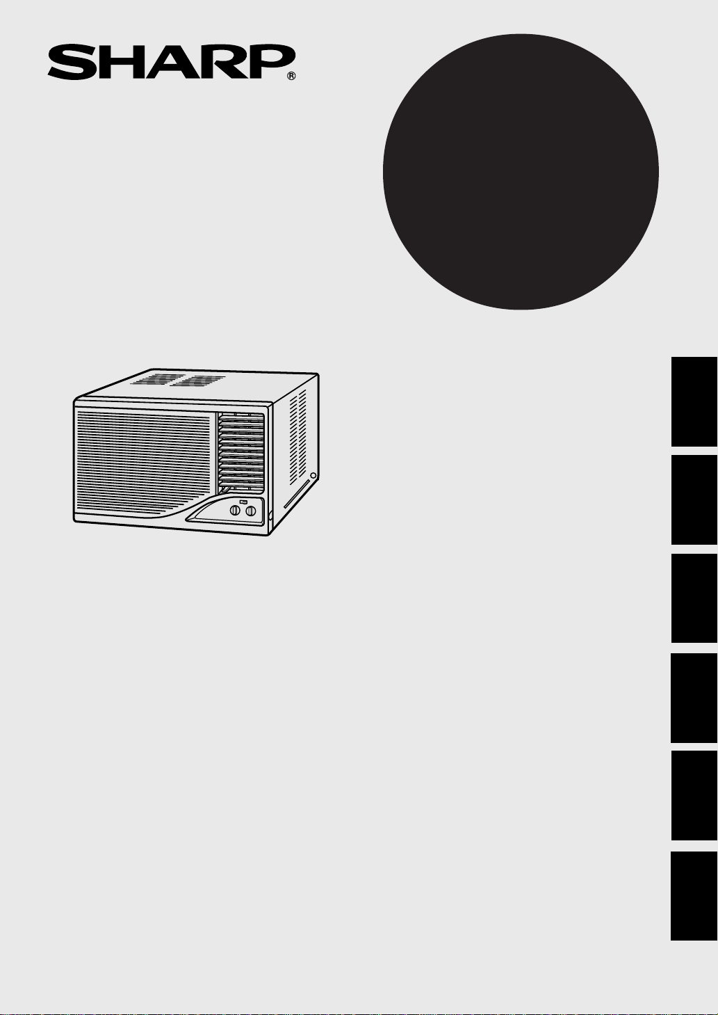
PARTS NAMES AND DIMENSIONS
Front panel
1
2
Grille
Air filter (behind the grille)
3
4
Up/Down air flow adjustment louvres
5
Left/Right air flow adjustment louvres
6
Cabinet
7
V entilation lever
8
Control panel
Stopper screws
9
(on left and right side)
10
Power cord and plug
1
B
DIMENSIONS
2
3
4
5
D
E
C
A
6
7
8
9
10
A (mm)
B (mm)
C (mm)
D (mm)
E (mm)
This equipment complies with the requirements of Directives 73/23/EEC as
amended by 93/68/EEC.
We reserve the right to change the materials and specifications without notice.
470
350
583 (centre 590)
239
33 (centre 40)
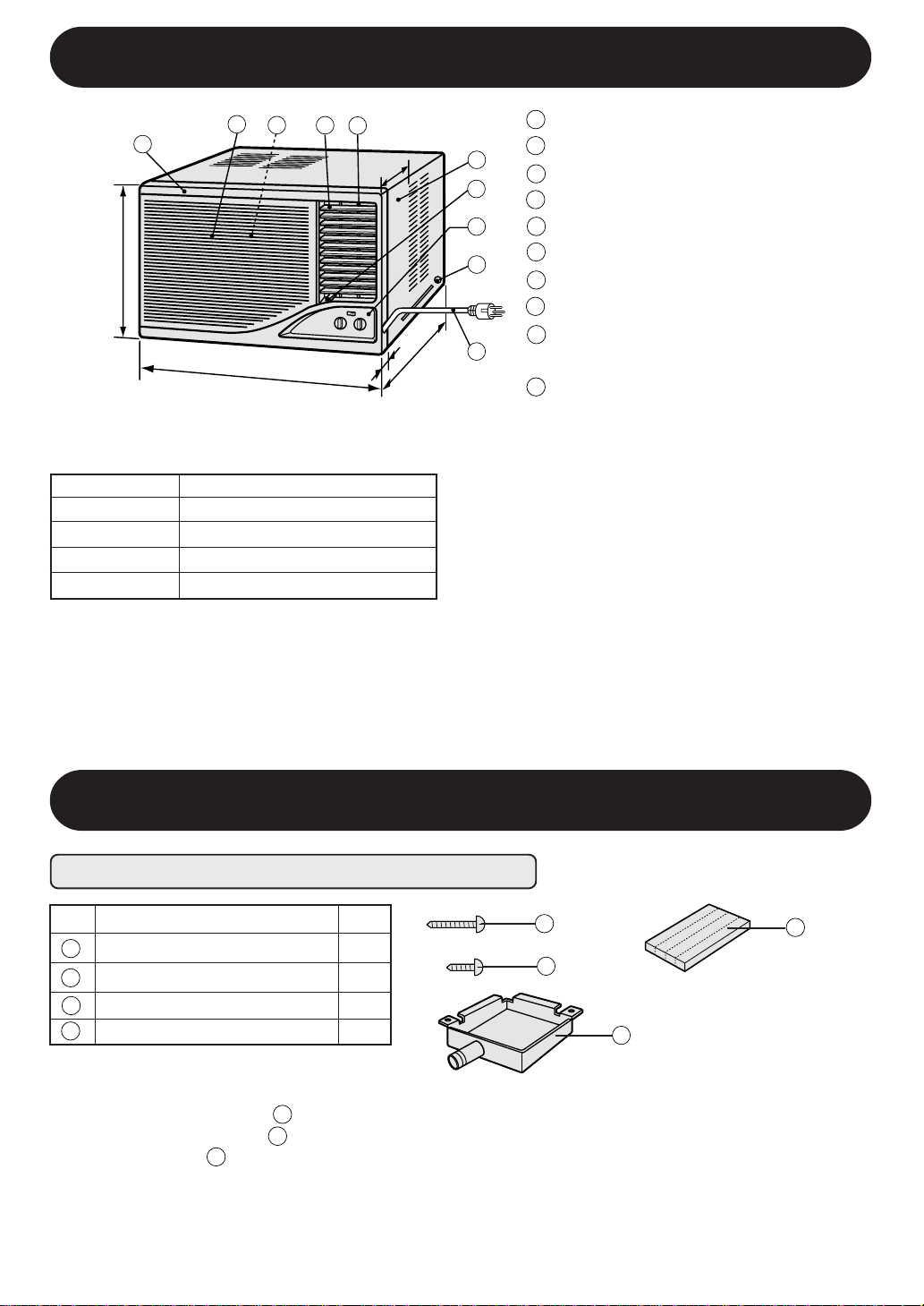
INST ALLA TION INSTRUCTIONS
ITEMS P ACKED WITH THIS UNIT
Accessories
GOLD SCREWS (2.5cm/1")
1
GOLD SCREW (1.2cm/0.5")
2
3
BOTTOM GASKET
4
DRAIN TRAY
Q'ty
9
2
1
1
1
2
4
3
The long GOLD SCREWS ( ) are used to secure the cabinet to the mounting frame.
The short GOLD SCREW ( ) is used to secure the drain tray to the cabinet.
The DRAIN TRAY ( ) is attached to the cabinet, in case drainage is necessary in high humidity
district, or in case you do not like the splashing sound of the non-drain function.
See page E-3 for detail installation instructions.
4
1
2
E-1
Page 5

INST ALLA TION INSTRUCTIONS
LOCA TION
Install the air conditioner to the opening dimensions shown below.
Never install the unit where each of the air inlet is blocked.
The air conditioner should be installed with a strong external support to minimize noise and vibration,
and for the purpose of safe installation, repair, replacement and secure positioning.
Avoid installing the air conditioner where it is exposed to direct sunlight.
36.0~37.0 cm
(14 3/16"~14 9/16")
More than 20 cm (8")
48.0~49.0 cm
~19 5/16"
(18 7/8"
8~20 cm(3"~8")
More than 20 cm (8")
)
More than 40 cm (16")
More than 20 cm (8")
Air inlet
Air outlet
Air inlet
More than 20 cm (8")
Air inlet
Air outlet
Air inlet
GROUNDING
WARNING: THIS APPLIANCE MUST BE GROUNDED.
This appliance is equipped with a cord having a grounding wire with
a grounding tab.
The plug must be plugged into an outlet that is properly
installed and grounded.
More than 40 cm
(16")
About 1 cm
(3/8")
Plug
ENGLISH
Grounding tab
FUSE
For safe, trouble free operation, connect the power cord of the unit to a properly rated
10 amp independent circuit with a time delay fuse or a circuit breaker.
E-2
Page 6

INST ALLA TION INSTRUCTIONS
INSTALLATION
WARNING:
Turn off and disconnect the unit before working.
(1)
Open the grille (Fig.1) by gently pulling
1
the arrow marked portion. Remove the
air filter (Fig.2) from the front panel.
Unscrew the screw fixing the front panel
to the chassis. (Fig.2)
Keep the screw as it will be used later.
CAUTION;
Do not provide stress to the opened grille. It
may damage the hinges. When the grille is
opened extremely wide, the hinge joints may
come off. In such case, push the hinge joint
into the hinge support (upper and lower accordingly) and replace the grille.
(2)
Close the grille firmly, and remove the
front panel by pulling the front panel at
the lower corners towards you for about
3 cm (1" ). Then lift it up and pull it towards you. (Fig.3)
Hinge
Air filter
Grille
Grill
2
Fig.1
2
1
Front panel
Hinge support
Fig.2
Hinge joint
(1)
Unscrew the 4 stopper screws (3 stopper
2
3
screws for model AF-A1288) of the cabinet (Fig.4). Keep the front screw and the
angle as they will be used later in step 6.
(2)
Slide the chassis out from the cabinet
by pulling the hand hold located at the
bottom center of the chassis. (Fig.4)
Attach the provided drain tray to the cabinet in case drainage becomes necessary.
Use the 2 short gold screws (1.2cm/0.5")
to fix it. (Fig.5)
Cabinet
E-3
Front panel
1
Cabinet
Angle
Chassis
Drain tray
Fig.3
Fig.4
Fig.5
Page 7

INST ALLA TION INSTRUCTIONS
When drainage is necessary
If water drainage is necessary in high humidity district, or if you do not like the splashing
sound of the non-drain function, remove the
rubber cap on the bottom of the chassis. Cut
the rubber cap in cross, working from the bottom and remove the rubber pieces with a
plier.(Fig.6)
A hose of an appropriate length have to be
attached to the drain tray's drain outlet. (Fig.7)
Chassis
Fig.6
Rubbur cap
Cabinet
Drain tray
Fig.7
4
5
(1)
Install the cabinet into the installation
opening.(Fig.8)
(2)
Secure the cabinet to the mounting frame
using the 9 long gold screws. (2.5cm/1").
(Fig.8)
(3)
Stuff the gasket to the gap between the
mounting frame and the unit to seal outside air. (Fig.8)
Slide the chassis back into the cabinet.
(1)
(Fig. 9)
(2)
Secure the chassis to the cabinet using
the screw and angle removed in step 2.
Push the angle into the gap between the
chassis and the cabinet. Hook the angle
to the slit of the cabinet, next screw it on
to the chassis. (Fig. 10)
(3)
Replace the front panel. (Fig.11)
Slide the crank shaft into the opening of
the louver link at the back of the front panel.
(Fig.12)
Cabinet
Gasket
Fig.9
Cabinet
Slit
Fig.8
ENGLISH
Angle
Chassis
Fig.10
Crank shaft
Open the grille and secure the front panel
(4)
with the screw removed in step 1 (Fig.13).
Replace the air filter and close the grille
firmly.
Front panel
E-4
Grille
Fig.11
Front panel
Louver link
Front panel back view
Fig.12
Fig.13
Page 8

OPERA TION INSTRUCTIONS
PRECAUTIONS
POWER CORD REPLACEMENT
WARNING: Use only the manufacturer specified power cord, parts code QACC-A217JBE0 for its replacement.
Replacemant should be conducted by a qualified technician or a serviceman. Consult your dealer for detail information concerning replacement of the power cord.
WAIT FOR 3 MINUTES BEFORE RESTARTING THE COOLING OPERATION
Whenever you turn the air conditioner OFF, wait for at least three (3) minutes before restarting the unit.
If you restart the air conditioner within three minutes, a protective device in the unit may cause the air conditioner to
shut off. This protective device will prevent cooling operation for about 5 minutes.
IF A POWER FAILURE OCCURS DURING OPERATION, BE SURE TO TURN OFF THE AIR CONDITIONER
After resumption of power supply, restart the air conditioner . If the power was of f less than three minutes, make sure
to wait for at least three minutes before restarting the unit.
If the air conditioner is not turned off during a power failure, the resumption of power supply will cause excessive
voltage. The air conditioner will be over-loaded and will not operate for about 5 minutes.
TO STOP THE UNIT, TURN THE SELECTOR KNOB TO THE "OFF" POSITION.
ALWAYS USE A FUSE WITH THE PROPER AMP RATING
Never use wire, pins or anything other than the proper fuse. The product may be damaged and fire or other hazards
may be resulted. In replacing a blown fuse, or if there is the problem of constant fuse blowing, contact your dealer or
our service centre.
VENTILATE THE ROOM PERIODICALLY DURING USE, ESPECIALLY IF GAS APPLIANCES ARE USED.
NOTES ON OPERA TION
POWER SUPPL Y VOL T AGE
If the power supplied to the unit is not within plus / minus 10 % of the specified rating, the unit may not function and
the fuse may blow.
OPERA TING TEMPERA TURE RANGE
INDOOR TEMP. OUTDOOR TEMP.
upper limit
COOLING
lower limit
D.B. = Dry-bulb W.B. = Wet-bulb
NOISE LEVEL
Noise from the air conditioner will be louder at night than in the daytime. This is because noise in the surroundings
is comparatively low at night. If you feel that noise of the air conditioner is too loud, switch the "SELECTOR" knob to
the "LOW COOL" position.
WA TER IN THE BOTTOM TRAY
Water will be collected at the bottom tray of the unit. This is normal condition. Water condenses on the evaporator
coil in the front of the unit and is channeled to the rear where it is picked up by the condenser fan. The water is blown
onto the condensor coil fins, this creates a "splashing" sound which is normal. When the tray is filled up with water,
excessive water will be drained outside through a grooved channel in the tray.
32˚C D.B. 43˚C D.B.
23˚C W.B. -
21˚C D.B. 21˚C D.B.
15˚C W.B. -
A built-in protective device might prevent the unit from operating when used
out of this range.
Condensation might form on the air outlet when the unit operates continuously
in the COOL mode when the humidity is
over 80 percent.
E-5
Page 9

MODES OF OPERATION
HOW TO OPERA TE
25
1
Control panel
1
Auto swing switch
2
Thermostat knob
3
Selector knob
4
Ventilation lever
5
SELECTOR KNOB
Use to select the desired mode. (COOLING , FAN or OFF)
Both the fan and cooling operation
OFF
FAN
ONLY
are off.
This setting can be used to circulate
air whenever cooling is not desirable.
The fan will operate at medium speed.
LOW
COOL
MED
COOL
3
Cooling for sleeping comfort with low
fan speed.
Fan operates at medium speed;
cooling power at medium.
4
ENGLISH
E-6
Fan and cooling at maximum power.
HIGH
COOL
Page 10

MODES OF OPERATION
THERMOST AT KNOB
Use to adjust the desired room temperature setting.
The air conditioner will automatically maintain the room temperature according to the THERMOSTA T
setting. Turning the knob clockwise will lower room temperature. You need to experiment to find out
which setting suits you most.
AUTO SWING SWITCH
Use to activate automatic louvre movement during LOW COOL ( ), MED COOL ( ) and HIGH
COOL ( ).Adjust the louvres to change the direction of air flow for uniform and efficient cooling of the
room. Set the AUTO SWING switch ( ) ON ( ), and the Left/Right air flow adjustment louvres will
swing continuously to provide better circulation of cool air. The louvres will stop at the position when
the switch is turned off. Also use the switch to adjust the Left/Right air flow adjustment louvres to the
desired position. Never attempt to move the Left/Right air flow adjustment louvres manually, or manually force the louvre movement to stop during swing operation.The AUTO SWING switch ( ) will not
activate the louvres when the SELECTOR KNOB is set to FAN ONLY ( ).
UP/DOWN AIR FLOW ADJUSTMENT
Move the Up/Down air flow adjustment louvres with your fingers. Do not adjust these louvres extremely downward during LOW COOL ( ), MED COOL ( ) and HIGH COOL ( ) for a long time.
Condensation may form on the louvres.
VENTILATION LEVER
If air in your room is stale, set the VENTILA TION lever to the RIGHT (OPEN) position. This will remove
stale air from the room. The VENTILATION lever should normally be kept in the LEFT (CLOSED)
position during cooling operation for maximum cooling effect.
Up/Down air flow
adjustment louvres
Left/Right air flow
adjustment louvres
(Auto Swing)
Ventilation lever
CLOSED
OPEN
E-7
Page 11

CLEANING AND MAINTENANCE
WARNING: Turn off and unplug the unit before performing any cleaning or maintenance.
CLEANING THE FIL TER
If the filter is clogged with dust, the amount of air flow will be reduced, resulting in poor cooling
performance. The filter should be cleaned every 10 days. At the beginning of every cooling season
or if the air conditioner has not been used for a long period, clean the filter before starting to operate the unit.
REMOVE THE FILTER
1.
Open the grille by gently pulling the arrow
marked portion. Then lift and unhook the bottom of the air filter and remove it.
CAUTION;
Do not provide stress to the opened grille. It may
damage the hinges. When the grille is opened
extremely wide, the hinge joints may come off.
In such case, replace the grille in the way shown
in page E-3 "CAUTION"
2.
CLEAN THE FILTER
To remove dust from the filter, use a vacuum
cleaner or wash it with clean water.
If the filter is very dirty, wash it with detergent
and rinse carefully with clean water. Dry the
filter with a soft cloth. Do not expose the filter
to heat or dry it under direct sunlight.
.
Grille
Air filter
Air filter
2
1
ENGLISH
3.
RE-INSTALL THE FILTER
Fit the top hooks, and then hook the bottom of
the air filter. Close the grille firmly. Never operate the unit without installing the filter or the
grille open. It may result in serious damage to
the unit.
Air filter
CLEANING OF THE FRONT PANEL, GRILLE AND CABINET
To clean the front panel, grille and cabinet, wipe with a soft, dry cloth or with a cloth moistened with a
mild soap. Rinse carefully by wiping with a damp cloth and dry completely.
Avoid splashing the unit with water. Excessive water will affect electrical insulation and fire may be
resulted during operation.
Never use harsh chemicals or abrasive cleaners on any part of the unit. To avoid damaging the unit,
do not use hot water of over 50°C when cleaning.
OILING OF THE COMPRESSOR AND FAN MOTOR IS UNNECESSARY
The compressor is permanently lubricated and is hermetically sealed. The fan motor is lifetime
sealed and does not require oiling.
E-8
Page 12

BEFORE CALLING FOR SERVlCE
IF YOUR AIR CONDITIONER DOES NOT OPERATE PROPERLY, PLEASE CHECK THE
FOLLOWING ITEMS BEFORE CALLING FOR SERVICE.
AIR CONDITIONER DOES NOT OPERATE AT ALL
• Is the power cord loosened or unplugged?
• Is the fuse blown or has the circuit breaker been tripped?
• Did you restart the unit within 3 minutes after power failure? If the power was off for less than
3 minutes, and you restart the air conditioner within 3 minutes, a protective device may cause the air
conditioner to shut off, preventing cooling operation for about 5 minutes.
AIR CONDITIONER DOES NOT COOL PROPERLY
• Is the SELECTOR set to FAN ONLY ( )?
Cooling will not be conducted in FAN ONLY ( ) . Change the SELECTOR setting to LOW COOL
( ), MED COOL ( ) or HIGH COOL ( ).
• Is the filter covered with heavy dirt?
A dirty filter can cause the cooling coils to get frozen. If this happens, clean the filter and replace.
Run the air conditioner on the FAN ONLY ( ) setting until defrostation.
• Is the THERMOSTAT ( ) set properly?
If your room is too warm, adjust the THERMOSTAT knob to a higher cooling setting.
If your room is too cool, adjust the THERMOSTAT knob to a lower cooling setting.
• Is the VENTILATION lever set in the RIGHT (OPEN) position?
The lever should be set in the LEFT (CLOSED) position during cooling operation.
• Are the windows exposed to direct sunlight?
Close curtains or blinds to minimize the heat in the room.
• Are the windows or doors open?
Close all windows and doors for maximum cooling effect.
LEFT / RIGHT AIR FLOW ADJUSTMENT LOUVRES DO NOT SWING
• Is the crank shaft fit properly into the louvre link?
Remove the front panel, and replace it again. Make sure to slide the crank shaft into the opening of
the louvre link at the back of the front panel. (See page E-4, step 5-(3))
• Is the SELECTOR set to FAN ONLY ( )? The auto swing louvre is activated only at LOW COOL
( ),MED COOL ( ) or HIGH COOL ( ) settings.
E-9
Page 13

Printed in Thailand
TINS-A507JBR0
TL
7MO
1
SHARP CORPORATION
Osaka, Japan
 Loading...