

Page 1
AE-X4M30PU
SERVICE MANUAL
S3302AEX4M3PUT
MULTI SPLIT TYPE
ROOM AIR CONDITIONERS
OUTDOOR UNIT
MODEL
In the interests of user-safety (Required by safety regulations in some countries)
the set should be restored to its original condition and only parts identical to those
specied should be used
AE-X4M30PU
CONTENTS
SPECIFICATION
SPECIFICATION ---------------------------------------------------------------------------------------------------------- 2
EXTERNAL DIMENSION ------------------------------------------------------------------------------------------------4
CAPACITY TABLE --------------------------------------------------------------------------------------------------------5
ELECTRICAL PARTS ----------------------------------------------------------------------------------------------------8
CYCLE PARTS -------------------------------------------------------------------------------------------------------------8
WIRING DIAGRAMS ----------------------------------------------------------------------------------------------------- 8
EXPLANATION OF CIRCUIT AND OPERATION
BLOCK DIAGRAM ------------------------------------------------------------------------------------------------------12
FUNCTIONS --------------------------------------------------------------------------------------------------------------13
TROUBLE SHOOTING GUIDE
SELF-DIAGNOSIS FUNCTION --------------------------------------------------------------------------------------16
PROTECTIVE FUNCTIONS AND OPERATIONS --------------------------------------------------------------25
REFRIGERATION CYCLE
DISASSEMBLING PROCEDURE
PROCEDURE ------------------------------------------------------------------------------------------------------------29
Position of the thermistors. --------------------------------------------------------------------------------------------32
How to disassemble the control box assembly -------------------------------------------------------------------33
---------------------------------------------------------------------------------------------------------------2
--------------------------------------------------------------12
----------------------------------------------------------------------------------------16
-----------------------------------------------------------------------------------------------26
------------------------------------------------------------------------------------------29
This document has been published to be used for after sales service only.
The contents are subject to change without notice.
1
Page 2
AE-X4M30PU
SPECIFICATION
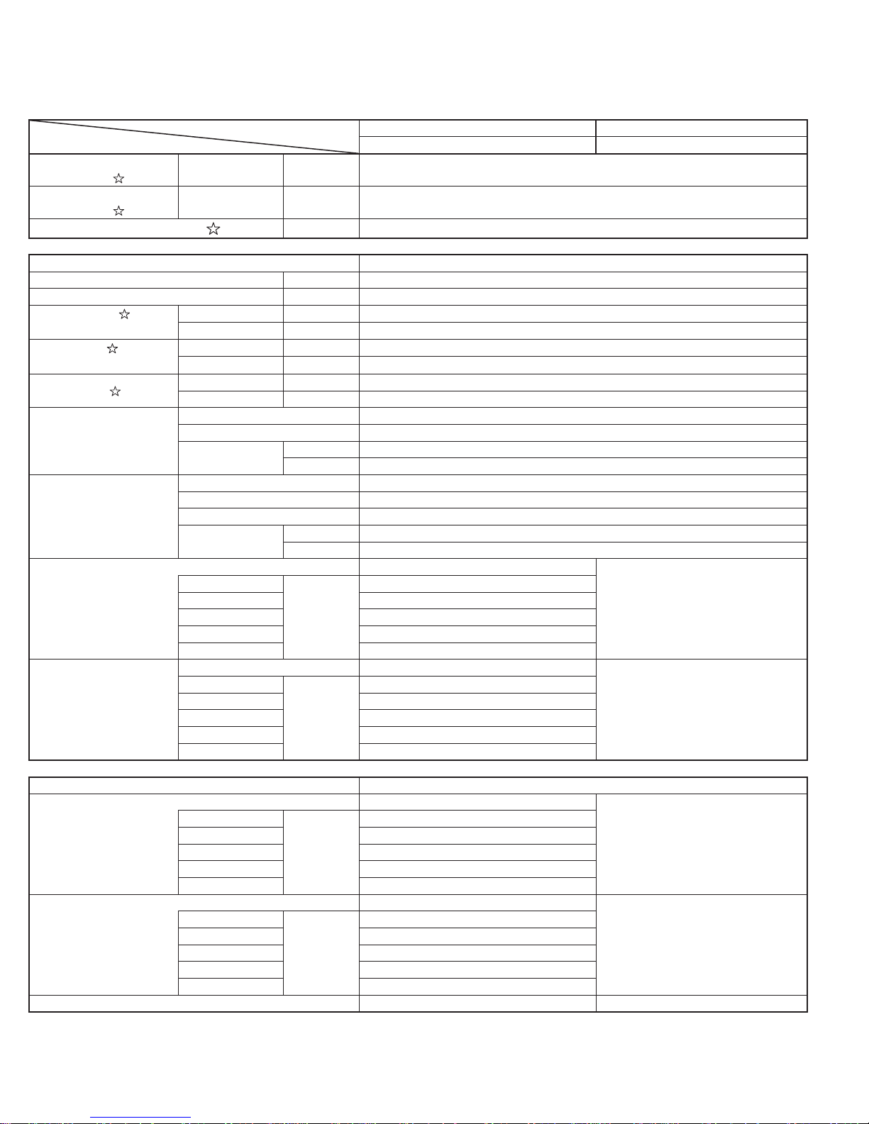
SPECIFICATION
MODEL
ITEMS
Rated cooling capacity
(Min. - Max.)
Rated heating capacity
(Min. - Max.)
Moisture removal (at cooling)
Electrical data
Phase Single
Rated frequency Hz 60
Rated voltage V 208/230
Rated current
(Min.-Max.)
Rated input
(Min.-Max.)
Power factor
Compressor
Refrigerant system
Noise level
(at cooling)
Noise level
(at heating)
Fan system
Drive Direct drive
Air ow quantity
(at cooling)
Air ow quantity
(at heating)
Fan Cross ow fan Propeller fan
9K&7K&7K&7K Btu/h 29000 ( 12000 ~ 31000)
9K&7K&7K&7K Btu/h 33000 ( 12000 ~ 37000)
pints/h 1.7×3 & 2.1
Cool A 13.6 ( 3.3 ~ 15.6) *
Heat A 12.6 ( 3.7 ~ 14.3) *
Cool W 3080 ( 640 ~ 3530)
Heat W 2860 ( 800 ~ 3250)
Cool % 98 *
Heat % 99 *
Type Twin rotary
Model SNB172FEKMT
Oil charge
Evaporator Louver Fin and Grooved tube type
Condenser Corrugate Fin and Grooved tube type
Control Expansion valve
Refrigerant
07PU
09PU 39 / 26
12PU 44 / 27
15PU 44 / 32
18PU 45 / 33
07PU
09PU 40 / 28
12PU 43 / 29
15PU 44 / 34
18PU 46 / 35
07PU
09PU 343 / 198 ( 9.7 / 5.6)
12PU 382 / 216 ( 10.8 / 6.1)
15PU 466 / 307 ( 13.2 / 8.7)
18PU 477 / 311 ( 13.5 / 8.8)
07PU
09PU
12PU 410 / 244 ( 11.6 / 6.9)
15PU 505 / 332 ( 14.3 / 9.4)
18PU 512 / 336 ( 14.5 / 9.5)
type FV50S
oz. ( cc) 27.4 ( 700)
type R410A
oz. ( g) 88.2 ( 2500)
dB(A)
dB(A)
CFM
3
/min)
(m
CFM
3
/min)
(m
AY-XPC07PU/09PU/12PU/15PU/18PU AE-X4M30PU
High / Soft
38 / 26
High / Soft
39 / 28
High / Soft
332 / 198 ( 9.4 / 5.6)
High / Soft
332 / 230 ( 9.4 / 6.5)
343 / 230 ( 9.7 / 6.5)
INDOOR UNIT OUTDOOR UNIT
53
55
1802 ( 51)
1802 ( 51)
2
Page 3
AE-X4M30PU
MODEL
ITEMS
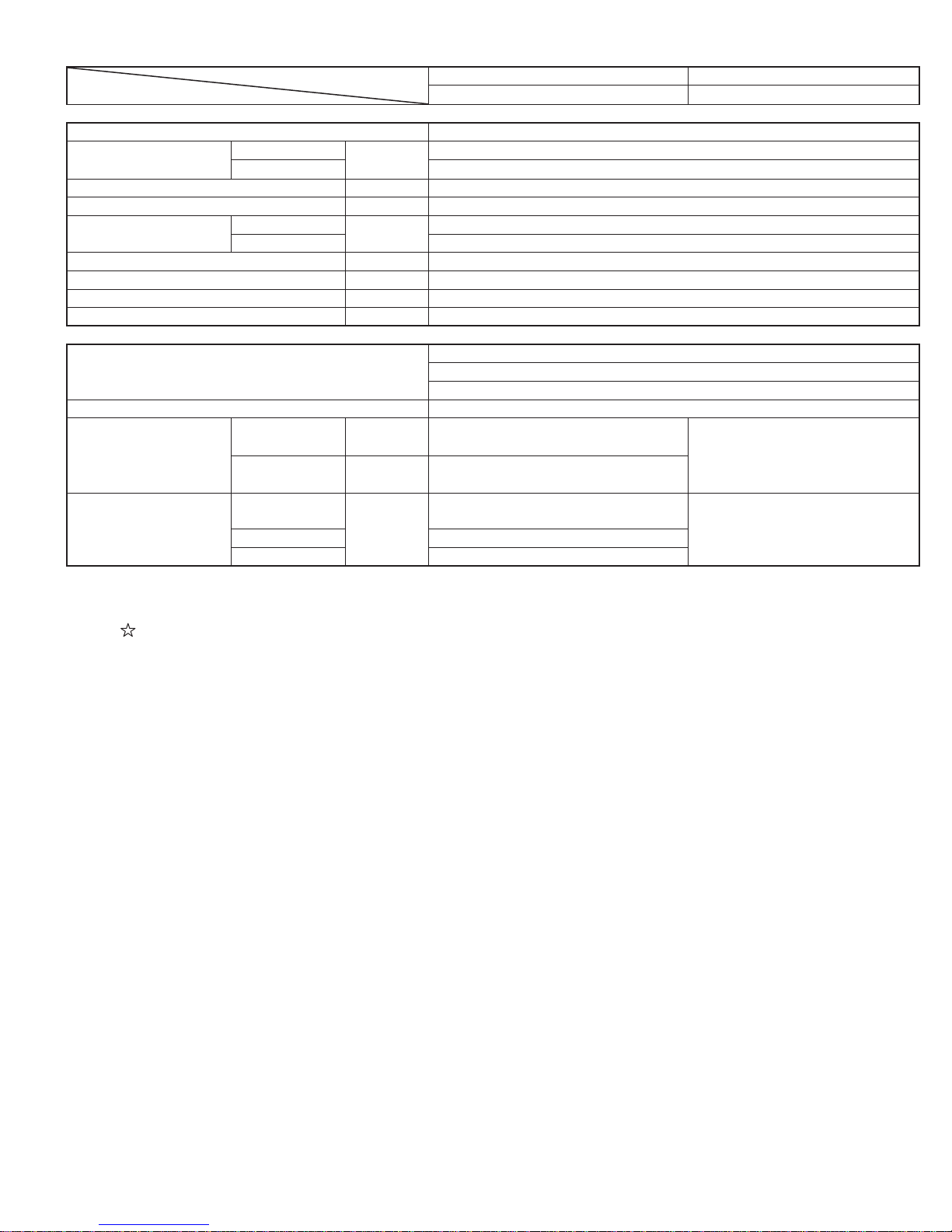
Connections
Refrigerant coupling Flare type
Refrigerant tube size
( Gas line)
Refrigerant tube size (Liquid line) inch (mm) 1/4 ( 6.35)
Minimum - Maximum length ( per unit) ft ( m) 10 - 82 ( 3 -25)
Maximum length
Maximum charge-less length ft ( m) 164 ( 50)
Maximum height difference ft ( m) 49 ( 15)
Additional charge oz./ft ( g/m) 0.16 ( 15)
Drain pipe O.D. inch (mm) 5/8 (16)
Others
Safety device
Air llters Polypropylene net (Washable)
Net dimensions
(Width x Height x Depth)
Net weight
7K, 9K, 12K
15K, 18K 1/2 (12.7)
2 units
3 or 4 units 230 ( 70)
07PU , 09PU ,
12PU
15PU , 18PU
07PU , 09PU ,
12PU
15PU 28.7 ( 13)
18PU 29.8 ( 13.5)
inch (mm)
ft ( m)
inch
(mm)
inch
(mm)
lb. (kg)
AY-XPC07PU/09PU/12PU/15PU/18PU AE-X4M30PU
3/8 ( 9.52)
164 ( 50)
Compressor: Thermal protector
Fan motors: Thermal fuse
Fuse, Micro computer control, Pressure switch
36-7/32 x 11-13/32 x 9-7/16
( 920 x 290 x 240)
38 x 12-5/16 x 9-27/32
( 965 x 313 x 250)
22 ( 10)
INDOOR UNIT OUTDOOR UNIT
35 x 31-1/2 x 12-19/32
( 890 x 800 x 320)
137 ( 62)
NOTE: Test conditions are based on AHRI 210/240. ( Refrigerant piping length [per unit] : 25ft[7.6m])
* : Voltage is 230V
: Representative connection
3
Page 4
AE-X4M30PU
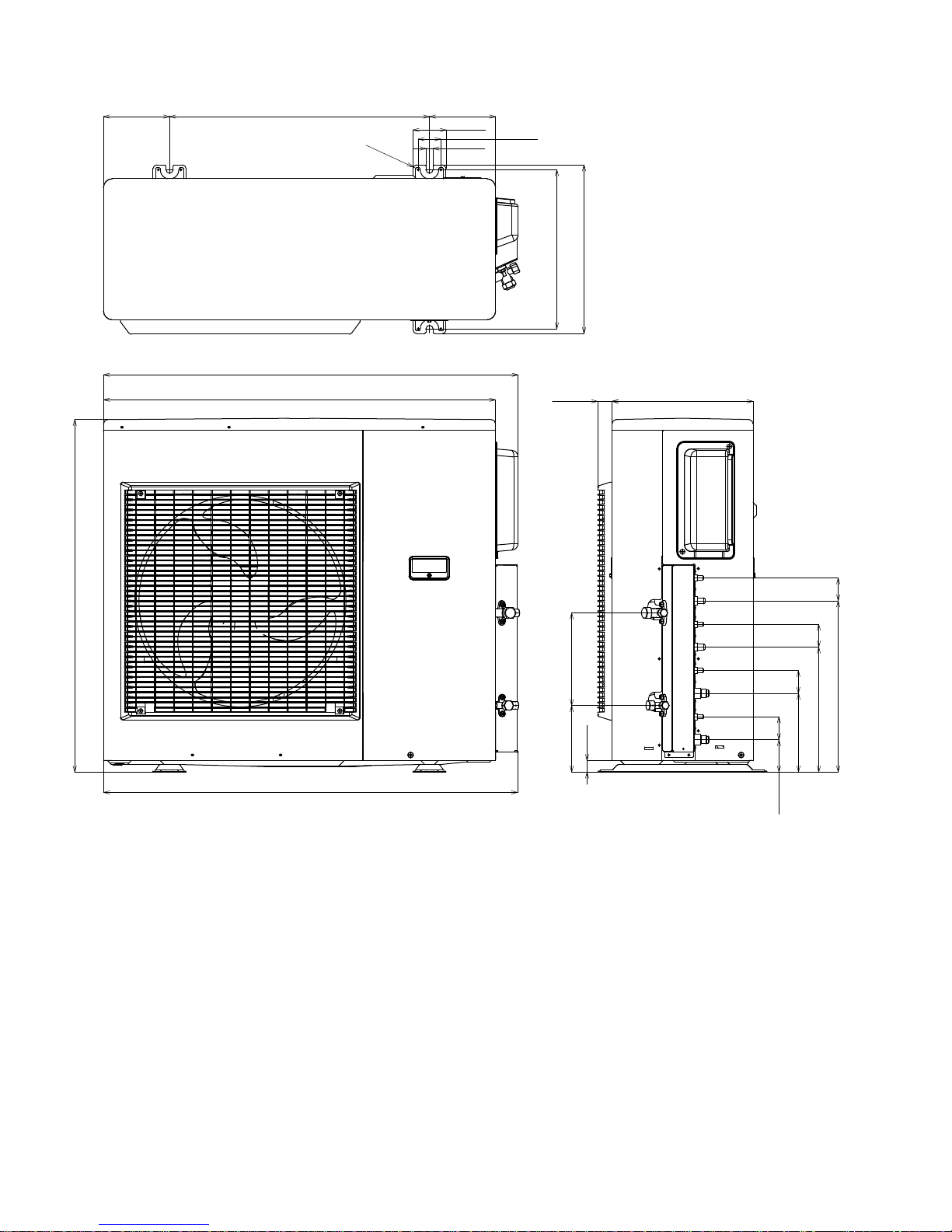
EXTERNAL DIMENSION
5.9 (150)
23.2 (590)
37 (941)
35 (890)
R0.3 (8.5)
5.9 (150)
3 (75)
0.6 (16)
2 (51.3)
14.2 (361)
15.1 (383)
1.3 (32.7)
Length unit : inch (mm)
12.6 (320)
31.5 (800)
37 (940)
8.3 (210)5.9 (151.1)
1 (26.2)
2 (52)
2 (52)
7 (178.6)
2.9 (73.6)
2 (52)
2 (52)
15.3(388.6)
11.2 (283.6)
4
Page 5
CAPACITY TABLE
COOLING CAPACITY TABLE
Operating
Status
4-indoor unit
operation
3-indoor unit
operation
Indoor unit
combination
A B C D A B C D Rating ( Min - Max) 208V 230V
18 12 7 7 11,864 7,909 4,614 4,614 29,000 (12,000 - 31,000) 3,080 (640 - 3,530) 15.1 (3.7 - 17.2) 13.6 (3.3 - 15.6)
18 9 9 9 11,600 5,800 5,800 5,800 29,000 (12,000 - 31,000) 3,080 (640 - 3,530) 15.1 (3.7 - 17.2) 13.6 (3.3 - 15.6)
18 9 9 7 12,140 6,070 6,070 4,721 29,000 (12,000 - 31,000) 3,080 (640 - 3,530) 15.1 (3.7 - 17.2) 13.6 (3.3 - 15.6)
18 9 7 7 12,732 6,366 4,951 4,951 29,000 (12,000 - 31,000) 3,080 (640 - 3,530) 15.1 (3.7 - 17.2) 13.6 (3.3 - 15.6)
18 7 7 7 13,385 5,205 5,205 5,205 29,000 (12,000 - 31,000) 3,080 (640 - 3,530) 15.1 (3.7 - 17.2) 13.6 (3.3 - 15.6)
15 15 7 7 9,886 9,886 4,614 4,614 29,000 (12,000 - 31,000) 3,080 (640 - 3,530) 15.1 (3.7 - 17.2) 13.6 (3.3 - 15.6)
15 12 9 9 9,667 7,733 5,800 5,800 29,000 (12,000 - 31,000) 3,080 (640 - 3,530) 15.1 (3.7 - 17.2) 13.6 (3.3 - 15.6)
15 12 9 7 10,116 8,093 6,070 4,721 29,000 (12,000 - 31,000) 3,080 (640 - 3,530) 15.1 (3.7 - 17.2) 13.6 (3.3 - 15.6)
15 12 7 7 10,610 8,488 4,951 4,951 29,000 (12,000 - 31,000) 3,080 (640 - 3,530) 15.1 (3.7 - 17.2) 13.6 (3.3 - 15.6)
15 9 9 9 10,357 6,214 6,214 6,214 29,000 (12,000 - 31,000) 3,080 (640 - 3,530) 15.1 (3.7 - 17.2) 13.6 (3.3 - 15.6)
15 9 9 7 10,875 6,525 6,525 5,075 29,000 (12,000 - 31,000) 3,080 (640 - 3,530) 15.1 (3.7 - 17.2) 13.6 (3.3 - 15.6)
15 9 7 7 11,447 6,868 5,342 5,342 29,000 (12,000 - 31,000) 3,080 (640 - 3,530) 15.1 (3.7 - 17.2) 13.6 (3.3 - 15.6)
15 7 7 7 12,083 5,639 5,639 5,639 29,000 (12,000 - 31,000) 3,080 (640 - 3,530) 15.1 (3.7 - 17.2) 13.6 (3.3 - 15.6)
12 12 12 9 7,733 7,733 7,733 5,800 29,000 (12,000 - 31,000) 3,080 (640 - 3,530) 15.1 (3.7 - 17.2) 13.6 (3.3 - 15.6)
12 12 12 7 8,093 8,093 8,093 4,721 29,000 (12,000 - 31,000) 3,080 (640 - 3,530) 15.1 (3.7 - 17.2) 13.6 (3.3 - 15.6)
12 12 9 9 8,286 8,286
12 12 9 7 8,700 8,700 6,525 5,075 29,000 (12,000 - 31,000) 3,080 (640 - 3,530) 15.1 (3.7 - 17.2) 13.6 (3.3 - 15.6)
12 12 7 7 9,158 9,158 5,342 5,342 29,000 (12,000 - 31,000) 3,080 (640 - 3,530) 15.1 (3.7 - 17.2) 13.6 (3.3 - 15.6)
12 9 9 9 8,923 6,692 6,692 6,692 29,000 (12,000 - 31,000) 3,080 (640 - 3,530) 15.1 (3.7 - 17.2) 13.6 (3.3 - 15.6)
12 9 9 7 9,405 7,054 7,054 5,486 29,000 (12,000 - 31,000) 3,080 (640 - 3,530) 15.1 (3.7 - 17.2) 13.6 (3.3 - 15.6)
12 9 7 7 9,943 7,457 5,800 5,800 29,000 (12,000 - 31,000) 3,080 (640 - 3,530) 15.1 (3.7 - 17.2) 13.6 (3.3 - 15.6)
12 7 7 7 10,545 6,152 6,152 6,152 29,000 (12,000 - 31,000) 3,080 (640 - 3,530) 15.1 (3.7 - 17.2) 13.6 (3.3 - 15.6)
9 9 9 9 7,250 7,250 7,250 7,250 29,000 (12,000 - 31,000) 3,080 (640 - 3,530) 15.1 (3.7 - 17.2) 13.6 (3.3 - 15.6)
9 9 9 7 7,676 7,676 7,676 5,971 29,000 (12,000 - 31,000) 3,080 (640 - 3,530)
9 9 7 7 8,156 8,156 6,344 6,344 29,000 (12,000 - 31,000) 3,080 (640 - 3,530) 15.1 (3.7 - 17.2) 13.6 (3.3 - 15.6)
9 7 7 7 8,700 6,767 6,767 6,767 29,000 (12,000 - 31,000) 3,080 (640 - 3,530) 15.1 (3.7 - 17.2) 13.6 (3.3 - 15.6)
7 7 7 7 7,050 7,050 7,050 7,050 28,200 (12,000 - 30,400) 2,950 (640 - 3,330) 14.4 (3.7 - 16.2) 13.0 (3.3 - 14.7)
18 18 9 - 11,600 11,600 5,800 - 29,000 (12,000 - 31,000) 3,080 (620 - 3,530) 15.1 (3.6 17.2) 13.6 (3.2 - 15.6)
18 18 7 - 12,140 12,140 4,721 - 29,000 (12,000 - 31,000) 3,080 (620 - 3,530) 15.1 (3.6 17.2) 13.6 (3.2 - 15.6)
18 15 12 - 11,600 9,667 7,733 - 29,000 (12,000 - 31,000) 3,080 (620 - 3,530) 15.1 (3.4 - 16.9) 13.6 (3.1 - 15.3)
18 15 9 - 12,429 10,357 6,214 - 29,000 (12,000 - 31,000) 3,080 (620 - 3,530) 15.1 (3.4 - 16.9) 13.6 (3.1 - 15.3)
18 15 7 - 13,050 10,875 5,075 - 29,000 (12,000 - 31,000) 3,080 (620 - 3,530) 15.1 (3.4 - 16.9) 13.6 (3.1 - 15.3)
18 12 12 - 11,743 7,829 7,829 - 27,400 (12,000 - 31,000) 2,980 (600 - 3,500) 14.6 (3.4 - 17.0) 13.2 (3.1 - 15.4)
18 12 9 - 12,646 8,431 6,323 - 27,400 (12,000 - 31,000) 2,980 (600 - 3,500) 14.6 (3.4 - 17.0) 13.2 (3.1 - 15.4)
18 12 7 * 13,330 8,886 5,184 * 27,400 (12,000 - 31,000) 2,980 (600 - 3,500) 14.6 (3.4 - 17.0) 13.2 (3.1 - 15.4)
18 9 9 * 13,700 6,850 6,850 * 27,400 (12,000 - 31,000) 2,980 (600 - 3,500) 14.6 (3.4 - 17.0) 13.2 (3.1 - 15.4)
18 9 7 * 14,506 7,253 5,641 * 27,400 (12,000 - 31,000) 2,980 (600 - 3,500) 14.6 (3.4 - 17.0) 13.2 (3.1 - 15.4)
18 7 7 * 15,413 5,994 5,994 * 27,400 (12,000 - 31,000) 2,980 (600 - 3,500) 14.6 (3.4 - 17.0) 13.2 (3.1 - 15.4)
15 15 12 - 10,357 10,357 8,286 - 29,000 (12,000 - 31,000) 3,080 (600 - 3,480) 15.1 (3.4 - 16.9) 13.6 (3.1 - 15.3)
15 15 9 - 11,154 11,154 6,692 - 29,000 (12,000 - 31,000) 3,080 (600 - 3,480) 15.1 (3.4 - 16.9) 13.6 (3.1 - 15.3)
15 15 7 * 11,757 11,757
15 12 12 - 10,538 8,431 8,431 - 27,400 (12,000 - 31,000) 2,980 (600 - 3,500) 14.6 (3.4 - 17.0) 13.2 (3.1 - 15.4)
15 12 9 * 11,417 9,133 6,850 * 27,400 (12,000 - 31,000) 2,980 (600 - 3,500) 14.6 (3.4 - 17.0) 13.2 (3.1 - 15.4)
15 12 7 * 12,088 9,671 5,641 * 27,400 (12,000 - 31,000) 2,980 (600 - 3,500) 14.6 (3.4 - 17.0) 13.2 (3.1 - 15.4)
15 9 9 * 12,455 7,473 7,473 * 27,400 (12,000 - 31,000) 2,980 (600 - 3,500) 14.6 (3.4 - 17.0) 13.2 (3.1 - 15.4)
15 9 7 * 13,258 7,955 6,187 * 27,400 (12,000 - 31,000) 2,980 (600 - 3,500) 14.6 (3.4 - 17.0) 13.2 (3.1 - 15.4)
15 7 7 * 14,172 6,614 6,614 * 27,400 (12,000 - 31,000) 2,980 (600 - 3,500) 14.6 (3.4 - 17.0) 13.2 (3.1 - 15.4)
12 12 12 * 9,133 9,133 9,133 * 27,400 (10,600 - 29,200) 3,010 (600 - 3,440) 14.7 (3.4 - 16.8) 13.3 (3.1 - 15.2)
12 12 9 * 9,964 9,964 7,473 * 27,400 (10,600 - 29,200) 2,990 (600 - 3,420)
12 12 7 * 10,606 10,606 6,187 * 27,400 (10,600 - 29,200) 2,990 (600 - 3,420) 14.6 (3.4 - 16.7) 13.2 (3.1 - 15.1)
12 9 9 * 10,960 8,220 8,220 * 27,400 (10,600 - 29,200) 2,990 (600 - 3,420) 14.6 (3.4 - 16.7) 13.2 (3.1 - 15.1)
12 9 7 * 11,314 8,486 6,600 * 26,400 (10,600 - 28,800) 2,690 (600 - 3,310) 13.1 (3.4 - 16.1) 11.9 (3.1 - 14.6)
12 7 7 * 11,631 6,785 6,785 * 25,200 (10,600 - 27,600) 2,410 (600 - 2,960) 11.8 (3.4 - 14.4) 10.6 (3.1 - 13.0)
9 9 9 * 8,600 8,600 8,600 * 25,800 (10,600 - 28,200) 2,540 (600 - 3,120) 12.4 (3.4 - 15.2) 11.2 (3.1 - 13.8)
9 9 7 * 8,856 8,856 6,888 * 24,600 (10,600 - 27,000) 2,270 (600 - 2,780) 11.1 (3.4 - 13.6) 10.0 (3.1 - 12.3)
9 7 7 * 9,078 7,061 7,061 * 23,200 (10,600 - 25,600) 2,010 (600 - 2,460) 9.8 (3.4 - 12.0) 8.9 (3.1 - 10.9)
7 7 7 * 7,267 7,267 7,267 * 21,800 (10,600 - 24,000) 1,770 (600 - 2,160) 8.6 (3.4 - 10.5) 7.8 (3.1 - 9.5)
AE-X4M30PU
Cooling capacity (Btu/h)
6,214 6,214 29,000 (12,000 - 31,000) 3,080 (640 - 3,530) 15.1 (3.7 - 17.2) 13.6 (3.3 - 15.6)
5,486 * 29,000 (12,000 - 31,000) 3,080 (600 - 3,480) 15.1 (3.4 - 16.9) 13.6 (3.1 - 15.3)
Power input (W)
Rating (Min. - Max.)
Running curent (A)
Rating (Min. - Max.)
15.1 (3.7 - 17.2) 13.6 (3.3 - 15.6)
14.6 (3.4 - 16.7) 13.2 (3.1 - 15.1)
5
Page 6
AE-X4M30PU
Operating
Status
2-indoor unit
operation
1-indoor unit
operation
Indoor unit
combination
A B C D A B C D Rating ( Min - Max) 208V 230V
18 18 * - 14,500 14,500 * - 29,000 (11,500 - 30,200) 3,080 (630 - 3,480) 15.1 (3.6 - 16.9) 13.6 (3.3 - 15.3)
18 15 * - 15,818 13,182 * - 29,000 (11,500 - 30,200) 3,080 (630 - 3,480) 15.1 (3.6 - 16.9) 13.6 (3.3 - 15.3)
18 12 * * 16,440 10,960 * * 27,400 (10,000 - 28,800) 2,930 (630 - 3,320) 14.3 (3.6 - 16.2) 12.9 (3.3 - 14.6)
18 9 * * 17,600 8,800 * * 26,400 (10,000 - 28,800) 2,640 (630 - 3,320) 12.9 (3.6 - 16.2) 11.7 (3.3 - 14.6)
18 7 * * 17,856 6,944 * * 24,800 (10,000 - 28,800) 2,360 (630 - 3,320) 11.5 (3.6 - 16.2) 10.4 (3.3 - 14.6)
15 15 * * 13,700 13,700 * * 27,400 (11,000 - 30,200) 3,070 (660 - 3,590) 15.0 (3.8 - 17.5) 13.6 (3.4 - 15.8)
15 12 * * 14,111 11,289 * * 25,400 (9,900 - 27,400) 2,620 (580 - 3,300) 12.8 (3.3 - 16.1) 11.6 (3.0 - 14.5)
15 9 * * 14,625 8,775 * * 23,400 (9,900 - 27,400) 2,230 (580 - 3,300) 10.9 (3.3 - 16.1) 9.8 (3.0 - 14.5)
15 7 * * 14,864 6,936 * * 21,800 (9,900 - 26,400) 1,980 (580 - 3,020) 9.7 (3.3 - 14.7) 8.7 (3.0 - 13.3)
12 12 * * 11,100 11,100 * * 22,200 (8,300 - 25,600) 2,240 (500 - 3,210) 10.9 (2.9 - 15.6) 9.9 (2.6 - 14.1)
12 9 * * 11,543 8,657 * * 20,200 (8,300 - 24,400) 1,860 (500 - 2,810) 9.1 (2.9 - 13.7) 8.2 (2.6 - 12.4)
12 7 * * 11,747 6,853 * * 18,600 (8,300 - 23,000) 1,630 (500 - 2,450) 7.9 (2.9 - 11.9) 7.2 (2.6 - 10.8)
9 9 * * 9,000 9,000 * * 18,000 (8,300 - 22,200) 1,520 (500 - 2,270) 7.4 (2.9 - 11.1) 6.7 (2.6 - 10.0)
9 7 * * 9,225 7,175 * * 16,400 (8,300 - 20,400) 1,300 (500 - 1,940) 6.3 (2.9 - 9.5) 5.7 (2.6 - 8.6)
7 7 * * 7,400 7,400 * * 14,800 (8,300 - 18,400) 1,100 (500 - 1,620) 5.3 (2.9 - 7.9) 4.8 (2.6 - 7.2)
18 * * *
15 * * * 16,200 * * * 16,200 (7,200 - 18,000) 1,440 (500 - 1,730) 7.0 (2.9 - 8.5) 6.3 (2.6 - 7.6)
12 * * * 12,200 * * * 12,200 (5,800 - 13,200) 1,090 (420 - 1,280) 5.3 (2.4 - 6.3) 4.8 (2.2 - 5.7)
9 * * * 9,700 * * * 9,700 (5,800 - 10,800) 790 (420 - 920) 3.8 (2.4 - 4.5) 3.5 (2.2 - 4.1)
7 * * * 7,800 * * * 7,800 (5,800 - 9,000) 600 (420 - 700) 2.9 (2.4 - 3.4) 2.6 (2.2 - 3.1)
19,200 * * * 19,200 (7,200 - 21,000) 1,810 (500 - 2,190) 8.8 (2.9 - 10.7) 8.0 (2.6 - 9.7)
Cooling capacity (Btu/h)
* When connected indoor unit is not in operation.
- When no unit is connected.
HEATING CAPACITY TABLE
Operating
Status
4-indoor unit
operation
Indoor unit
combination
A B C D A B C D Rating ( Min - Max) 208V 230V
18 12 7 7 13,500 9,000 5,250 5,250 33,000 (12,000 - 37,000) 2,860 (800 - 3,250) 13.9 (4.1 - 15.8) 12.6 (3.7 - 14.3)
18 9 9 9 13,200 6,600 6,600 6,600 33,000 (12,000 - 37,000) 2,860 (800 - 3,250) 13.9 (4.1 - 15.8) 12.6 (3.7 - 14.3)
18 9 9 7 13,814 6,907 6,907 5,372 33,000 (12,000 - 37,000) 2,860 (800 - 3,250) 13.9 (4.1 - 15.8) 12.6 (3.7 - 14.3)
18 9 7 7 14,488 7,244 5,634 5,634 33,000 (12,000 - 37,000) 2,860 (800 - 3,250) 13.9 (4.1 - 15.8) 12.6 (3.7 - 14.3)
18 7 7 7 15,231 5,923 5,923 5,923 33,000 (12,000 - 37,000) 2,860 (800 - 3,250) 13.9 (4.1 - 15.8) 12.6 (3.7 - 14.3)
15 15 7 7 11,250 11,250 5,250 5,250 33,000 (12,000 - 37,000) 2,860 (800 - 3,250) 13.9 (4.1 - 15.8) 12.6 (3.7 - 14.3)
15 12 9 9 11,000 8,800 6,600 6,600 33,000 (12,000 - 37,000) 2,860 (800 - 3,250) 13.9 (4.1 - 15.8) 12.6 (3.7 - 14.3)
15 12 9 7 11,512 9,209 6,907 5,372 33,000 (12,000 - 37,000) 2,860 (800 - 3,250) 13.9 (4.1 - 15.8) 12.6 (3.7 - 14.3)
15 12 7 7 12,073 9,659 5,634 5,634 33,000 (12,000 - 37,000) 2,860 (800 - 3,250) 13.9 (4.1 - 15.8) 12.6 (3.7 - 14.3)
15 9 9 9 11,786 7,071 7,071 7,071 33,000 (12,000 - 37,000) 2,860 (800 - 3,250) 13.9 (4.1 - 15.8) 12.6 (3.7 - 14.3)
15 9 9 7 12,375 7,425 7,425 5,775 33,000 (12,000 - 37,000) 2,860 (800 - 3,250) 13.9 (4.1 - 15.8) 12.6 (3.7 - 14.3)
15 9 7 7 13,026 7,816 6,079 6,079 33,000 (12,000 - 37,000) 2,860 (800 - 3,250) 13.9 (4.1 - 15.8) 12.6 (3.7 - 14.3)
15 7 7 7 13,750 6,417 6,417 6,417 33,000 (12,000 - 37,000) 2,860 (800 - 3,250) 13.9 (4.1 - 15.8) 12.6 (3.7 - 14.3)
12 12 12 9 8,800 8,800 8,800 6,600 33,000 (12,000 - 37,000) 2,860 (800 - 3,250) 13.9 (4.1 - 15.8) 12.6 (3.7 - 14.3)
12 12 12 7 9,209 9,209 9,209 5,372 33,000 (12,000 - 37,000) 2,860 (800 - 3,250) 13.9 (4.1 - 15.8) 12.6 (3.7 - 14.3)
12 12 9 9 9,429 9,429
12 12 9 7 9,900 9,900 7,425 5,775 33,000 (12,000 - 37,000) 2,860 (800 - 3,250) 13.9 (4.1 - 15.8) 12.6 (3.7 - 14.3)
12 12 7 7 10,421 10,421 6,079 6,079 33,000 (12,000 - 37,000) 2,860 (800 - 3,250) 13.9 (4.1 - 15.8) 12.6 (3.7 - 14.3)
12 9 9 9 10,154 7,615 7,615 7,615 33,000 (12,000 - 37,000) 2,860 (800 - 3,250) 13.9 (4.1 - 15.8) 12.6 (3.7 - 14.3)
12 9 9 7 10,703 8,027 8,027 6,243 33,000 (12,000 - 37,000) 2,860 (800 - 3,250) 13.9 (4.1 - 15.8) 12.6 (3.7 - 14.3)
12 9 7 7 11,314 8,486 6,600 6,600 33,000 (12,000 - 37,000) 2,860 (800 - 3,250) 13.9 (4.1 - 15.8) 12.6 (3.7 - 14.3)
12 7 7 7 12,000 7,000 7,000 7,000 33,000 (12,000 - 37,000) 2,860 (800 - 3,250) 13.9 (4.1 - 15.8) 12.6 (3.7 - 14.3)
9 9 9 9 8,250 8,250 8,250 8,250 33,000 (12,000 - 37,000) 2,860 (800 - 3,250) 13.9 (4.1 - 15.8) 12.6 (3.7 - 14.3)
9 9 9 7 8,735 8,735 8,735 6,794 33,000 (12,000 - 37,000) 2,860 (800 - 3,250)
9 9 7 7 9,281 9,281 7,219 7,219 33,000 (12,000 - 37,000) 2,860 (800 - 3,250) 13.9 (4.1 - 15.8) 12.6 (3.7 - 14.3)
9 7 7 7 9,900 7,700 7,700 7,700 33,000 (12,000 - 37,000) 2,860 (800 - 3,250) 13.9 (4.1 - 15.8) 12.6 (3.7 - 14.3)
7 7 7 7 7,600 7,600 7,600 7,600 30,400 (12,000 - 34,000) 2,520 (800 - 2,950) 12.3 (4.1 - 14.4) 11.1 (3.7 - 13.0)
Heating capacity (Btu/h)
7,071 7,071 33,000 (12,000 - 37,000) 2,860 (800 - 3,250) 13.9 (4.1 - 15.8) 12.6 (3.7 - 14.3)
Power input (W)
Rating (Min. - Max.)
Power input (W)
Rating (Min. - Max.)
Running curent (A)
Rating (Min. - Max.)
Running curent (A)
Rating (Min. - Max.)
13.9 (4.1 - 15.8) 12.6 (3.7 - 14.3)
6
Page 7
AE-X4M30PU
Operating
Status
3-indoor unit
operation
2-indoor unit
operation
1-indoor unit
operation
Indoor unit
combination
A B C D A B C D Rating ( Min - Max) 208V 230V
18 18 9 - 13,200 13,200 6,600 - 33,000 (12,000 - 37,000) 2,780 (800 - 3,250) 13.6 (4.1 - 15.8) 12.3 (3.7 - 14.3)
18 18 7 - 13,814 13,814 5,372 - 33,000 (12,000 - 37,000) 2,780 (800 - 3,250) 13.6 (4.1 - 15.8) 12.3 (3.7 - 14.3)
18 15 12 - 13,200 11,000 8,800 - 33,000 (12,000 - 37,000) 2,780 (800 - 3,250) 13.6 (4.1 - 15.8) 12.3 (3.7 - 14.3)
18 15 9 - 14,143 11,786 7,071 - 33,000 (12,000 - 37,000) 2,780 (800 - 3,250) 13.6 (4.1 - 15.8) 12.3 (3.7 - 14.3)
18 15 7 - 14,850 12,375 5,775 - 33,000 (12,000 - 37,000) 2,780 (800 - 3,250) 13.6 (4.1 - 15.8) 12.3 (3.7 - 14.3)
18 12 12 - 13,114 8,743 8,743 - 30,600 (12,000 - 33,400) 2,720 (780 - 3,150) 13.3 (4.0 - 15.3) 12.0 (3.6 - 13.9)
18 12 9 - 14,123 9,415 7,062 - 30,600 (12,000 - 33,400) 2,720 (780 - 3,150) 13.3 (4.0 - 15.3) 12.0 (3.6 - 13.9)
18 12 7 * 14,886 9,924 5,789 * 30,600 (12,000 - 33,400) 2,720 (780 - 3,150) 13.3 (4.0 - 15.3) 12.0 (3.6 - 13.9)
18 9 9 * 15,300 7,650 7,650 * 30,600 (12,000 - 33,400) 2,720 (780 - 3,150) 13.3 (4.0 - 15.3) 12.0 (3.6 - 13.9)
18 9 7 * 16,200 8,100 6,300 * 30,600 (12,000 - 33,400) 2,720 (780 - 3,150) 13.3 (4.0 - 15.3) 12.0 (3.6 - 13.9)
18 7 7 * 17,213 6,694 6,694 * 30,600 (12,000 - 33,400) 2,720 (780 - 3,150) 13.3 (4.0 - 15.3) 12.0 (3.6 - 13.9)
15 15 12 - 11,357 11,357 9,086 - 31,800 (12,000 - 34,200) 2,710 (800 - 3,170) 13.2 (4.1 - 15.4) 12.0 (3.7 - 14.0)
15 15 9 - 12,231 12,231 7,338 - 31,800 (12,000 - 34,200) 2,710 (800 - 3,170) 13.2 (4.1 - 15.4) 12.0 (3.7 - 14.0)
15 15 7 * 12,892 12,892 6,016 * 31,800 (12,000 - 34,200) 2,710 (800 - 3,170) 13.2 (4.1 - 15.4) 12.0 (3.7 - 14.0)
15 12 12 - 11,769 9,415 9,415 - 30,600 (12,000 - 32,400) 2,750 (780 - 3,190) 13.4 (4.0 - 15.5) 12.1 (3.6 - 14.1)
15 12 9 * 12,750 10,200
15 12 7 * 13,500 10,800 6,300 * 30,600 (12,000 - 32,400) 2,750 (780 - 3,190) 13.4 (4.0 - 15.5) 12.1 (3.6 - 14.1)
15 9 9 * 13,909 8,345 8,345 * 30,600 (12,000 - 32,400) 2,750 (780 - 3,190) 13.4 (4.0 - 15.5) 12.1 (3.6 - 14.1)
15 9 7 * 14,806 8,884 6,910 * 30,600 (12,000 - 32,400) 2,750 (780 - 3,190) 13.4 (4.0 - 15.5) 12.1 (3.6 - 14.1)
15 7 7 * 15,828 7,386 7,386 * 30,600 (12,000 - 32,400) 2,750 (780 - 3,190) 13.4 (4.0 - 15.5) 12.1 (3.6 - 14.1)
12 12 12 * 10,200 10,200 10,200 * 30,600 (12,000 - 32,400) 2,940 (780 - 3,220) 14.3 (4.0 - 15.7) 13.0 (3.6 - 14.2)
12 12 9 * 11,127 11,127 8,345 * 30,600 (12,000 - 32,400) 2,940 (780 - 3,240) 14.3 (4.0 - 15.8) 13.0 (3.6 - 14.3)
12 12 7 * 11,845 11,845 6,910 * 30,600 (12,000 - 32,400) 2,940 (780 - 3,250) 14.3 (4.0 - 15.8) 13.0 (3.6 - 14.3)
12 9 9 * 12,240 9,180 9,180 * 30,600 (12,000 - 32,400) 2,940 (780 - 3,270)
12 9 7 * 13,114 9,836 7,650 * 30,600 (12,000 - 32,400) 2,940 (780 - 3,280) 14.3 (4.0 - 16.0) 13.0 (3.6 - 14.5)
12 7 7 * 14,123 8,238 8,238 * 30,600 (12,000 - 32,400) 2,940 (780 - 3,290) 14.3 (4.0 - 16.0) 13.0 (3.6 - 14.5)
9 9 9 * 10,200 10,200 10,200 * 30,600 (12,000 - 32,400) 2,940 (780 - 3,300) 14.3 (4.0 - 16.1) 13.0 (3.6 - 14.5)
9 9 7 * 11,016 11,016 8,568 * 30,600 (12,000 - 32,400) 2,960 (780 - 3,310) 14.4 (4.0 - 16.1) 13.0 (3.6 - 14.6)
9 7 7 * 11,191 8,704 8,704 * 28,600 (12,000 - 31,600) 2,530 (780 - 3,070) 12.3 (4.0 - 15.0) 11.2 (3.6 - 13.5)
7 7 7 * 8,600 8,600 8,600 * 25,800 (12,000 - 29,200) 2,180 (780 - 2,620) 10.6 (4.0 - 12.8) 9.6 (3.6 - 11.6)
18 18 * - 16,500 16,500 * - 33,000 (12,000 - 35,600) 3,040 (850 - 3,570) 14.8 (4.4 - 17.4) 13.4 (3.9 - 15.7)
18 15 * - 18,000 15,000 * - 33,000 (12,000 - 35,600) 3,040 (850 - 3,570) 14.8 (4.4 - 17.4) 13.4 (3.9 - 15.7)
18 12 * * 18,360 12,240 * * 30,600 (12,000 - 31,200) 3,030 (780 - 3,320) 14.8 (4.0 - 16.2) 13.4 (3.6 - 14.6)
18 9 * * 20,400 10,200 * * 30,600 (12,000 - 31,200) 3,030 (780 - 3,320) 14.8 (4.0 - 16.2) 13.4 (3.6 - 14.6)
18 7 * * 21,456 8,344 * * 29,800 (12,000 - 31,200) 2,880 (780 - 3,320) 14.0 (4.0 - 16.2) 12.7 (3.6 - 14.6)
15 15 * * 15,700 15,700 * * 31,400 (12,000 - 34,000) 2,970 (810 - 3,460) 14.5 (4.1 - 16.9) 13.1 (3.8 - 15.2)
15 12 * * 16,667 13,333 * * 30,000 (11,600 - 31,200) 3,110 (780 - 3,490) 15.2 (4.0 - 17.0) 13.7 (3.6 - 15.4)
15 9 * * 17,750 10,650 * * 28,400 (11,600 - 31,200) 2,840 (780 - 3,490) 13.8 (4.0 - 17.0) 12.5 (3.6 - 15.4)
15 7 * * 17,591 8,209 * * 25,800 (11,600 - 31,200) 2,430 (780 - 3,490) 11.9 (4.0 - 17.0) 10.7 (3.6 - 15.4)
12 12 * * 14,000 14,000 * * 28,000 (11,000 - 28,400) 3,040 (760 - 3,240) 14.8 (3.9 - 15.8) 13.4 (3.5 - 14.3)
12 9 * * 14,286 10,714
12 7 * * 14,400 8,400 * * 22,800 (11,000 - 28,400) 2,140 (760 - 3,240) 10.4 (3.9 - 15.8) 9.4 (3.5 - 14.3)
9 9 * * 10,700 10,700 * * 21,400 (11,000 - 28,400) 1,980 (770 - 3,240) 9.7 (3.9 - 15.8) 8.7 (3.6 - 14.3)
9 7 * * 10,688 8,313 * * 19,000 (11,000 - 26,000) 1,650 (770 - 2,830) 8.1 (3.9 - 13.8) 7.3 (3.6 - 12.5)
7 7 * * 8,200 8,200 * * 16,400 (11,000 - 22,800) 1,350 (770 - 2,300) 6.6 (3.9 - 11.2) 6.0 (3.6 - 10.2)
18 * * * 23,000 * * * 23,000 (11,000 - 25,000) 2,890 (880 - 2,990) 14.1 (4.5 - 14.6) 12.7 (4.1 - 13.2)
15 * * * 19,000 * * * 19,000 (10,000 - 21,600) 2,250 (870 - 2,810) 11.0 (4.5 - 13.7) 9.9 (4.0 - 12.4)
12 * * * 15,600 * * * 15,600 (8,600 - 17,000) 1,930 (850 - 2,340) 9.4 (4.4 - 11.4) 8.5 (3.9 - 10.3)
9 * * * 11,400 * * * 11,400 (8,600 - 15,600)
7 * * * 8,400 * * * 8,400 (8,600 - 12,000) 850 (850 - 1,370) 4.2 (4.4 - 6.7) 3.8 (3.9 - 6.1)
Heating capacity (Btu/h)
7,650 * 30,600 (12,000 - 32,400) 2,750 (780 - 3,190) 13.4 (4.0 - 15.5) 12.1 (3.6 - 14.1)
* When connected indoor unit is not in operation.
- When no unit is connected.
Power input (W)
Rating (Min. - Max.)
* * 25,000 (11,000 - 28,400) 2,490 (760 - 3,240) 12.1 (3.9 - 15.8) 11.0 (3.5 - 14.3)
1,230 (850 - 2,080) 6.0 (4.4 - 10.2) 5.5 (3.9 - 9.2)
Running curent (A)
Rating (Min. - Max.)
14.3 (4.0 - 15.9) 13.0 (3.6 - 14.4)
7
Page 8

AE-X4M30PU
ELECTRICAL PARTS
Fuse 1, 5 — QFS-GA065JBZZ(20A,250V)
Fuse 2 — QFS-GA062JBZZ(3.15A,250V)
Fuse 3, 6 — QFS-GA063JBZZ(2A,250V)
CYCLE PARTS
PARTS MODEL TYPE PARTS CODE
Compressor SNB172EFKMT 17.2cc DC TWIN ROTARY 1200W PCMPRA718JBEZ
Fan motor ARW8404SH DC MOTOR 8Poles, 60W CMOTLB541JBEZ
Refrigerant control
Expansion valve (Body) Φ1.8 PVLVRA047JBEZ
Expansion valve (Coil) DC12V RMOTSA050JBZZ
PRESSURE SWITCH ACB-4UB65 OFF:4.5MPa / ON:3.5MPa RBIM-A003JBEZ
Reverse Valve
(Body) SHF-7H-34U-P PVLVXA081JBEZ
(Coil) 50/60Hz 220-240V CCIL-A185JBKZ
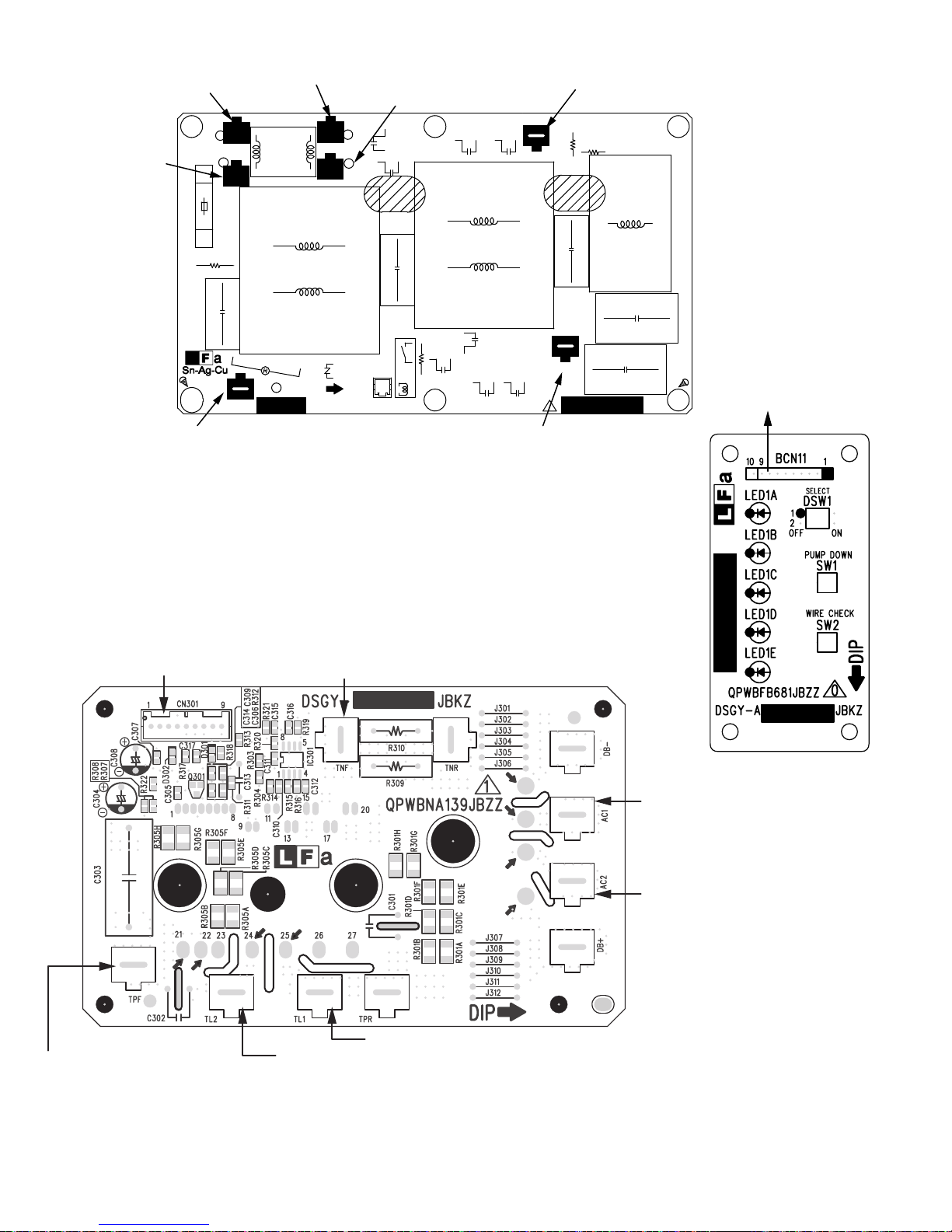
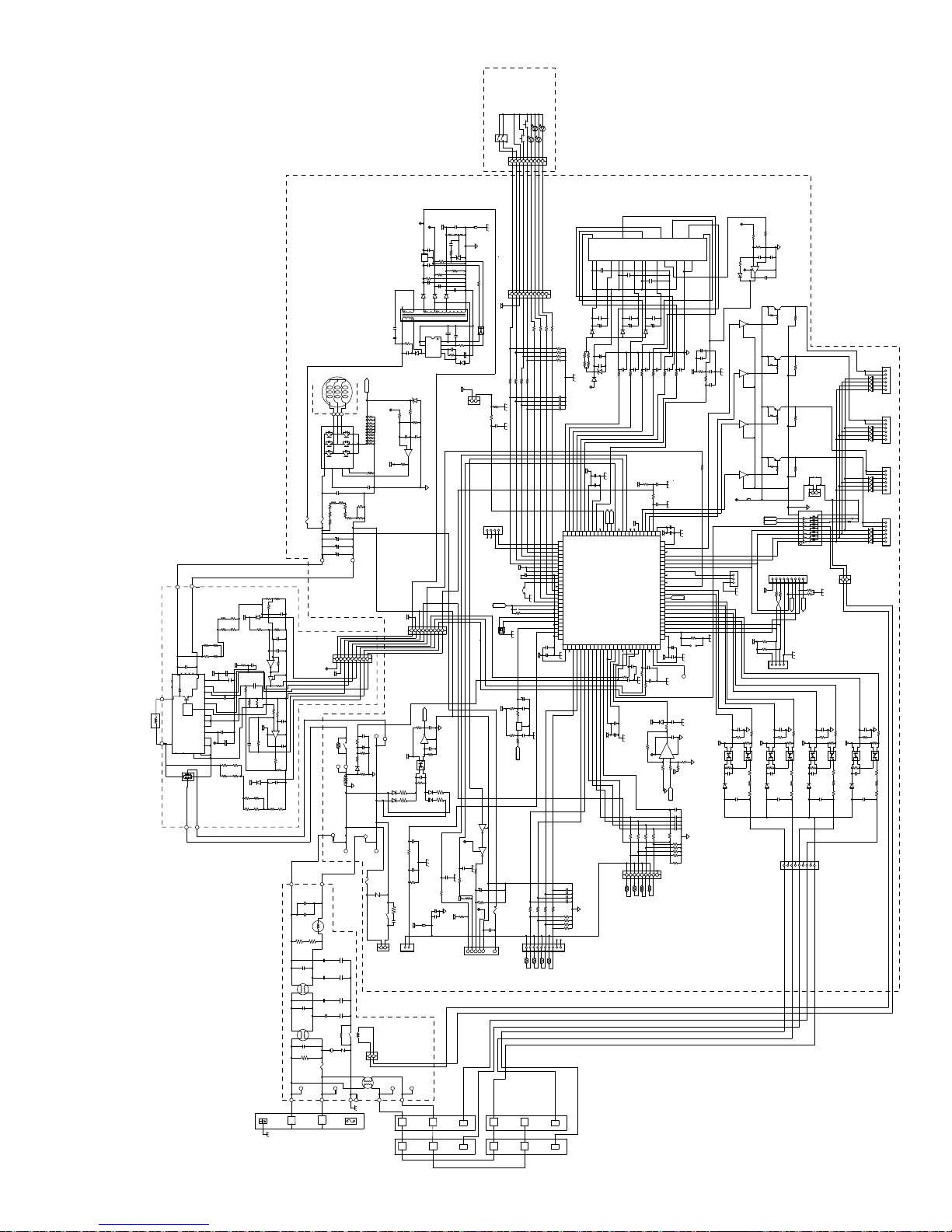
WIRING DIAGRAMS
WIRING DIAGRAM
CAUTION
(UNIT C)
(UNIT A)
The voltage is high at C8, C9, C11(electrolytic capacitors) on outdoor unit. For maintenance discharge at C8, C9, C11 to prevent electric shock,
in case that FUSE5(protector) has been fused, the voltage is kept high at C8, C9, C11.
BL
OR
RD
CN6
(UNIT D)
L1 L1
L2 L2
(UNIT B)
L1 L1
L2 L2
BK
VT
BL
BN
BK
CN2
BK
VT
The 4 LEDs of the display board will all flash synchronously. For patterns No.1, No.2
and No.4, only the LED corresponding with the abnormal unit will flash in the patterns
above, and the LED for the normal unit will flash in the slow flashing cycle.
BL
BN
OR
RD
G/Y
BL
L1
L2
BN
BL
BN
G/Y
BL
BN
T23
T22
T21
T20
CE011
EXV.
UNIT A
CN12A
20A
250V
EXV.
UNIT B
CN12B
C1
RY3
C2
L3
EXV.
UNIT C
CN12C
1
2
PRESSURE
SWITCH
4WAY
VALVE
FILTER BOARD
C3
L4
EXV.
UNIT D
CN12D
The microcomputer’s GND line which
control the thermistor,etc. share the
same line of 330V line. This circuit is
non-insulation type. Do not touch
CN15B
the control circuit components as it
may result in electrical shock hazard.
Do not earth osilloscope etc. during
measurement, as it may result in
damage.
CN4
RY1
NR2
T11
C4
C5
L5
T10
T13
BL
T14
BN
UNIT D
TH9
YL
CN8M
FUSE2
250V
3.15A
CT1
UNIT C
TH8
BN
PTC1
MRY1
TH7
WT
UNIT B
UNIT A
TH6
BL
9
BCN13
CN301
AC1
DB301
GY
+
-
BK
T15
AC2
PFC MODULE BOARD
BK
CN8A
LED1A
LED1B
LED1C
LED1D
GN
DSW1
1
2
OFF
PUMP DOWN
WIRE CHECK
TL1
PFCM
301
BK: BLACK
BL: BLUE
BN: BROWN
LED pattern
No.
RD
OR
CN11
BCN11
ON
SW1
SW2
Example: No.3 Overheat error (Compressor, Power module)
FUSE3
2A
C9 C11
+
250V
FUSE6
+
L1
TL2
TPF
TNF
YL
BL
BT11
C8
+
BT12
OR: ORANGE
GY: GRAY
RD: RED
GN: GREEN
WT: WHITE
YL: YELLOW
Abnormal comments
Normal
Abnormal signal line
Short circuit of the thermistor
Overheat error (Compressor, Power module)
Pressure switch error
Open circuit of the thermistor
Power module(IPM) abnormality
Abnormal AC current
Abnormal wire check
Cycle temperature error
EEPROM error
Rotation error of the fan motor
Thermal fuse error of terminal board
Compressor rotation error
Power factor (PFC)module error
or clock signal error
3
4
5
8
2A
250V
FUSE5
20A
250V
C14
N
G(/Y): GREEN/YELLOW
VT: VIOLET
DC FAN MOTOR
CN3
2
1
RD
U
T7
WT
V
T8
V
W
T9
OR
IPM
U
W
8
Page 9
AE-X4M30PU
from Terminal Board
Power Supply (Black)
from MAin PWB BT6 (Blue)
from Exporsion Valve A
from Exporsion Valve B
from Exporsion Valve C
from Exporsion Valve D
from Thermistor
Comp. Temp.
Heat Exchange T emp.
Outdoor Temp/
Suction
from Suction Thermistor
from Fan Motor
from Compressor (U)(Red)
from Compressor (V)(White)
from Compressor (W)(Orange)
to Filter PWB CN14
(THERMAL FUSE)
CN2
2
6
(VALVE A)
1
6
(VALVE B)
1
6
(VALVE C)
1
6
(VALVE D)
1
9
(THERMISTOR A)
1
1
(DC FAN MOTOR)
CN3
8
12V
IC9
Q6AQ6BQ6C
CN12A
C
E8B
D22A
D23A
D24A
D25A
CN12BCN12C
C
B
E
D22B
D23B
D24B
D25B
C
B
E
D22C
D23C
D24C
D25C
Q6D
E
C
B
CN12D
D22D
D23D
D24D
D25D
10
CN8M
CN8A
1
○
R104
R245
C100
R109
R103
R100
5V
C24
0V
C23
D7
D12
C20
C26
IC4
15V
C25
D6
C19
D26
C89
JP26
JP24
JP23
(THERMISTOR M)
C48
R101
JP25
R241
R240
R49
FB2
C54D
C54C
C54B
C54A
C47
1
C69
C68
C67
C66
C64
Q3
C99
(To CN14)
2
MRY_IN(BLUE)
MRY1
9
16
C123
FB3
C61
E
9
TR1
16
R242
BCN14
C124
C128
C45
C31
C125
C126
C103
C106
C107
C60
FU6
JP76
JP22
1
8
IC7
1
IC5
C32
C33
51
C90
75
4
CNM
(MONITOR)
9
(FLASH WRITER EEPROM)
FB1
E
Q4
250V/2A
C21
JP69
R243
JP21
C127
from PFCM PWB
AC1 (Black)
PTC1
CN15A(12V)
1
JP93
10
CN11
MRY_OUT(BLACK)
R53
R52
R55
R51
R43
C300
C301
R44
OSC1
50
76
JP94
1
1
1
BCN13
(To CN301)
9
IC3
JP77
T9
(ORANGE)
R263
JP58
CN-2
R255
C98
8
1
JP92
26
C93
IC1
1 25
C95
100
5
CND
1
R76
R102
R107
R108
R73
R75
R17
C105
C27
C85
D14
JP66
JP78
T8
(WHITE)
R54
1
(DISPLAY)
C104
C102
C101
C77
C74
C94
R105
PC6
1
2
D5
0V-P
C84
JP73
JP65
(RED)
from Pressure
Switch
(PRESSURE SWITCH)
1
2
CN15B
2
R258
R259
C137
R96D
R96C
R96B
R96A
R31D
C59
C58
R57
R56
C57
C56
JP7
C30
C46
CN-1
PC2D
1
R106
C83
Q6
C82
2
3
4
1
PC3
R238
FU3
250V/2A
C15
43
D4
C16
4
IC2
5
JP70
T7
CN6
9
R32D
R33D
2
3
4
2
3
C81
D17
1
C18
C14
250V/20A
FU5
from Terminal Board
Unit D "2", Unit C "2", Unit B "2", Unit A "2", "L1"
B
D18C
14
PC1C
PC2B
1
D13
RY1
R31B
R33B
2
3
4
2
3
R147
C97
(BROWN)
BT13
FU2
N
A
(TERMINAL BOARD)
R31A
C39B
R32B
R33A
D18B
C38B
4
1
PC1B
PC2A
4
1
C37B
R35B
R91
R90
C79
CT1
T13
(BROWN)
(To F-T10)
250V/3.15A
R180
C11
3
2
T14
1
2
3
BT14
(BLUE)
(To F-T11)
R89
D2
(BLUE)
C39A
C37A
R35A
C38A
NR2
DIP
R32A
D18A
1
PC1A
4
(To MRYIN)
T6
(BLUE)
C129
C8
BT6
(BLUE)
1
CN4
3
from Display PWB
JBKZ
DSGY-
2
to PFCM PWB AC2 (Gray)
QPWBNA221JBZZ
to Filter PWB T10 (Brown)
JBKZ
to Main PWB MRY1 (Blue)
to Filter PWB T11 (Blue)
FH-IXA
from 4 way Valve
(4 WAY VALVE)
C
D
R31C
C39C
C39D
R32C
R33C
D18D
2
3
C38C
C38D
4
1
PC2C
PC1D
4
1
2
R35C
R35D
3
C37D
C37C
R236
BT15
(GRAY)
D16
(GRAY)
(To P-AC2)
T15
R237
R235
R234
D15
C17
C43 C44C42
C41
C40
D11
C134
34
R50
ZD3
R262
R249
R250
C138
R261
R260 R248
29
C135
R233
C53
C122
C136
○
C133
R247
D27
IC11
C131
C132
C130
C51
○
○
○
○
○
D10
○
○
○
○
○
D9
C52
40
(YELLOW)
(To PFC-TPF)
BT11
C55
C72
1
C49
○
○
○
○
C70
D8
C50
C71
C9
(BLUE)
(To PFC-TNF)
to PFCM PWB TNF (Blue)
BT12
to PFCM PWB TPF (Yellow)
C10
9
Page 10
AE-X4M30PU
from Terminal Board AB (L1)
(Brown)
from Terminal Board
(L2) (Brown)
(FROM TERMINAL BOARD
(FROM TERMINAL BOARD
POWER SUPPLY L)
FU1
250V/20A
C1
from Control Box (Green/ Yellow)
from Terminal Board AB (L2)
(Blue)
T22
BT22
(BROWN)
INDOOR UNIT 1)
R4
BT20
(BROWN)
T20
L6
L3
(FROM TERMINAL BOARD
SA1
(GREEN/YELLOW)
T4
BT4
DSGY-
T23
(FROM TERMINAL BOARD
INDOOR UNIT N)
T21
POWER SUPPLY N)
NR1
DIP
JBKZ
from Terminal Board (L1)(Blue)
BT23
C13B
(BLUE)
C14B
BT21
(BLUE)
C2
RY3
R3
(FROM BCN14)
2
CN14
C11B
1
QPWBNA223JBZZ
C12B
C13C
from Main PWB (T14)(Blue)
C14C
(FROM T14)
L4
T10
(BROWN)
(FROM T13)
C12C
C11C
(BLUE)
2
R2
C3
C4
C5
R1
T11
from Main PWB (T13)(Brown)
L5
to Main PWB (CN11)
from Main PWB
BCN13
from Main PWB BT11 (Yellow)
from Main PWB BT12 (Blue)
from Main PWB
MRY1 OUT (Black)
from Main PWB T15 (Gray)
from PFC coil
from PFC coil
10
Page 11
AE-X4M30PU
UNIT D
WIRE CHECK SW
UNIT B
UNIT A
UNIT C
PUMP DOWN SW
SW2
LED1D
LED1B
2: PRE HEAT SELECT
1: -15°C AUTO OFF SELECT
1
2
SW1
DSW1
LED1A
LED1C
1
23456
(DISPLAY PWB)
789
BCN11
[BOARD IN]
5V
C23
FB1
25V
0.1μF
F
10KΩ
15V
3
1
BAJ5CC0T
R22
22KΩ
C19
D6
2
16
1
TR1
8
5
C85
250V
4700pF
R17
300KΩ
C105
250V
4700pF
7
5
D5
C27
Fp022 Vk1
Z
COMPRESSOR
T7
T9
T8
373839
VWU
NWNU NV
NOTE: All Resistance that is not indicated watt are 1/10W.
(MAIN PWB)
250V
2A
FU3
F
F
TNF
TPF
1/4W
F
1/4W
R305F
180KΩ
R305H
F
F
1/4W
1/4W
R305E
1/4W
180KΩ
180KΩ
R305D
180KΩ
F
R305B
630V
0.33μF
C303
1/4W
1/4W
25V
C308
R305C
100μF
R305A
- +
F
180KΩ
F
180KΩ
13
16
14
22
21
P
P
5V
N
N
N15N
VTH
11
10
RTH
12
9
25V
C307
CSC
0.1μF
8
CFOD
L
7
24
VFO
6
25V
C306
5
0.033μF
IGBT
DRIVER
COM
4
3
COM
2
VCC
C305
0.1μF
L1
TL1 TL2
1
NR
20
- +
PFCM301
PR
NR
25
19
15V
S
NR
R
NR
25V
C304
26
27
DB301
AC1
100μF
18
17
F
1/4W
R301D
R301B
180KΩ
1/4W
180KΩ
R301A
F
AC2
(PFCM PWB)
F
5V
180KΩ
D302
1/4W
R320
R305G
F
180KΩ
5V
0.1μF
C314
6.8kΩ
R318
50V
C313
1000pF
1KΩ
R311
10mΩ
R309
R314
C310 100pF
F
180KΩ
1/4W
5V
F
1/4W
R301C
180KΩ
F
R301H
R301F
180KΩ
1/4W
R301E
R301G
180KΩ
F W4/1
TERMINAL BOARD
2KΩ
R307
1.1KΩ
R308
F
15KΩ
R322
1μF
10V
C317
F
R321
15KΩ
F
0.1μF
C316
15KΩ
C315
0.1μF
6
5
-
+
1MΩ
IC301/B
R319
7
Q301
R317
1KΩ
R31010mΩ
1KΩ
R315
R316
1KΩ
5V
3
2
100pF
C312
-
+
8 4
15KΩ
1
C311
0.1μF
IC301/A
R313
13KΩ
R312
2KΩ
D301
F
C309
0.1μF
180KΩ
1/4W
F
F
R303
1KΩ
R304
2KΩ
1/4W
180KΩ
F
T11
275V
C5
C4
275V
510KΩR11/4W
1/4W
510KΩ
C3
1μF
275V
L4
C2
1μF
275V
L3
C1
275V
R4
1MΩ
1/2W
(FILTER PWB)
BT21
T21
L1
34
35
36
CIN
VSC
CFO
P
IPM/A QM1 (PS21A79)
250V
20A
FU5
BT11
T10
2.2μF
2.2μF
R2
C12C
C14B
1μF
FU1
T20
R233
24
25
40
19
630V
0.1μF
C14
R128
~R217
R127
R210
1/4W 82KΩF×8
×3
C11
C9
750uF
420V
C8
BT12
1
2
7
8
345
6
9
CN301
[PNI]
5V
15V
C97
50V
10KΩ
0.01μF
R147
C79
+
220μ
PTC1
MRY1/B
F
R91
1KΩ
R90
6.49KΩ
D2
BT6
T6
F
KΩ
R89
1
1/4W
CT1
0V
T14
T13
BT14
FU2
L5
250V
4700pF
250V
C14C
0.01μF
C13C
250V
250V
0.01μF
C11C
4700pF
250V
250V
C13B
0.01μF
4700pF
250V
250V
C11B
C12B
4700pF
0.01μF
1MΩ
1/2W
R3
RY3/B
RY3/A
1
CN14
NR1
SA1
510V
250V
20A
L6
BT20
T4
BT4
L2
FUSE
TEMP
102?
ZD3
F
F
1/4W
R50
1.8KΩ
KΩ
15V
62
R262
R261
,R254
C138
50V
C122
0.01μF
,R240~244
2W 140mΩF ×7
R49
-
+
6
5
7
5V
IC11/B
5.1KΩ
1/4W
R260
10KΩ
C72
50V
0.022μF
F
15.4KΩ
F
15.4KΩ
5V
1
2
345
BCN13
[BOARD IN]
R106
Q6
3.3KΩ
BT15
T15
10V
F
5V
3
4
PC3
1
2
0V
D13
1/2W
R235
150KΩ
R238
1/4W
39KΩ
R234
1/2W
D15
150KΩ
C301
50V
0.01μF
R44
10KΩ
BT13
0.1μF
25V
C300
250V
3.15A
NR2
510V
R43
10KΩ
100Ω
R180
1W
RY1/B
C129
5V
275VAC
0.033μF
2
1
1
3
CN2
CN4
[VH]
[PASK]
TEMP FUSE)
(TERMINAL BOARD
(4 WAY VALVE)
[PNI]
2
BT22
BT23
T23
T22
L1L1
A
B
F
R24
12V
0Ω
R25
R26
10KΩ
25V
C21
25V
C26
0.1μF
2
IC4
C25
25V
0.1μF
+
35V
150μF
D7
13
S8VDD
S
IC2
F
2.2KΩ
50V
1000pF
0V
0.1μF
R23
470Ω
R21
2.2KΩ
IC3
R82
R88
22KΩ
10KΩ
1/4W
+
+
C20
35V
C24
D12
680μF
25V
11
50V
C18
1μF
C17
1
FB
2
CL
3
VCC4D
C16
C15
50V
R16
F
261KΩ
2200pF
5V
(PRESSURE SWITCH B)
[PNISK]
R15
12345
6
470Ω
150μF
9
23
PC6
4 1
50V
2200pF
- +
R14
15KΩ
50V
2.2μF
D4
1
2
CN15B
[VH]
R259
10KΩ
789
10
CN11
5V
R96A
ΩK2.2 C69R
ΩK2.2 B69R
ΩK2.2 D69R
2.2KΩ
10KΩ
10KΩ
10KΩ
R54
R55 10KΩ
R56
R57
R258
10KΩ
50V
C137
0.01μF
0V
CN-1
2
134
5V
+
C98
25V
4.7μF
JP7
JP92
Q
R255
789
6
OSC1
DD
50V
0V
C83
1000pF
0.01μF
50V
C82
R105
22KΩ
50V
C81
0.01μF
D17
1/2W
R237
150KΩ
R236
D16
1/2W
150KΩ
0.1μF
25V
C101
10KΩ
R104
10V
C61
0V
100μF
+
5V
FB3
25V
C60
0.1μF
(FAN MOTOR)
L2L2
5V
BC
E
Q4
RN1405(T5L,F,T)
BC
15V
E
Q3
50V
0.01μF
C102
RN2402(T5L,F,T)
R101
10KΩ
R109
10KΩ
10V
C100
47μF
R103
3.3kΩ
R100
5V
6.8kΩ
R245
FU6
3.3kΩ
15V
630V
C99
0.1μF
5
8
123
4
CN3
[XNISK]
2
C
2
L1 L1
D
0.1μF
25V
C124
10MHz
5V
+
10V
C123
100μF
C33
50V
4.7μF
100KΩ
R80
C32
25V
0.1μF
R79
12
100Ω
3
IC5
R78
270Ω
25V
C31
R77
270Ω
0.1μF
R
10KΩ
10KΩ
10KΩ
250V
2A
R97D
R97A
R97C
R97B
1
678910
234
5
CN8M
TH7
TH6
TH8
TH9
(THERMISTOR M)
(Suction UnitD)
(Suction UnitA)
(Suction UnitB)
(Suction UnitC)
L2 L2
IPM/B
QM1(PS21A79)
7
1
VP
UP
VP19VVFB
VUFS
VP1
VUFB
VVFS12VP1
3
4
6
10
50V
C55
0.1uF
C70
50V
0.1uF
29VN28
13
27
26
FO
UN
WP
WN
VNC22VPC
VWFB
VWFS
VN1
VOT
21
14
15
16
18
23
C71
50V
0.1uF
(DISPLAY)
0.1uF
C49
50V
0.1uF
D8
C50
33Ω
1/4W
1/4W
33Ω
10KΩ
R263
25V
C135
R51
+
R162
R48
R52
R53
R47
R161
33Ω
1/4W
33Ω
1/4W
D4
D11
Z
15V
1000pF
~C59
50V
C56
5V
C30
+
100μF
25V
C93
PS0 26
PP4 16
PP5 17
PQ1 21
PQ2 22
PQ3 23
PQ4 24
PQ0 20
PQ5 25
VSS 18
VCC 19
PS1 27
PS2 28
PS3
29
PS4 30
PS5 31
VCC 32
VCC 33
VSS 34
C 35
PR0 36
PR1 37
PR2 38
PR3 39
PR4 40
PR5 41
MD2 42
MD1 43
MD0 44
X0 45
X1 46
VSS 47
INITX 48
PA2 49
VSS 50
06 0DP
95 7CP
85 6CP
75 5CP
65 4CP
55 3CP
45 2CP
35 1CP
25 0CP
15 CCV
C54A,C54B,C54C,C54D
50V 0.01uF
C54D
C54C
C54B
C54A
0V
10KΩ
R98A
R98B
R98C
6.8KΩ F
R98A,R98B,R98C,R98D
R98D
[XNISK]
0.1uF
C51
50V
C53
50V
25V
25V
100μF
100μF
50V
C136
R134
24V
10V
0.1μF
I
HH
PP1 13
PP2 14
PP3 15
36 2HRVA
26 01CCVA
16 1DP
C126
5V
C125
25V
C52
100μF
C133
100μF
D10
D9
50V
50V
0.1uF
C44
C40
C43 50V
1000pF
C41 50V
1000pF
1000pF
100Ω
100Ω
R137
R135
100Ω
100Ω
R136
5V
C77
10KΩ
R75
R73
1KΩ
5V
P86 2
P90 4
P91 5
P87 3
PF0 11
PP0 12
PM0 7
PM2 9
PM1 8
PM3 10
NMIX 6
IC1
17 6BP
47 1AP
37 0AP
27 7BP
07 5BP
46 01SSVA
96 4BP
86 3BP
76 2BP
56 0BP
66 1BP
50V
C103
50V
C106
0.01μF
0.01μF
1KΩ
R107
10KΩ
R102
C107
50V
0.01μF
25V
C104
0.1μF
1KΩ
R108
5V
0.1μF
25V
+
10V
R123
100μF
15V
10KΩ F
10KΩ
10KΩ
10KΩ
R66
10KΩ
R65
R64
R63
123
45678
CN8A
TH4
TH3
TH2
TH1
)
(THERMISTOR A)
(Suction)
ut door Temp)
(Compressor)
(O
(Heat Exchange
1000pF
R132
VCC 1
57 SSV
IC9/B
R120
9
100Ω
25V
001 SSV
99 58P
89 48P
79 38P
69 28P
59 18P
49 08P
39 7JP
29 6JP
19 5JP
09 4JP
98 3JP
88 2JP
78 1JP
68 0JP
58 2HP
48 1HP
38 0HP
28 5GP
18 4GP
08 3GP
97 2GP
87 1GP
77 0GP
67 CCV
5V
D26
F
2KΩ
50V
0.1μF
C74
5V
C128
1
-2+
R143
0V
R62
[XNISK]
C42
1000pF
R133
100Ω
50V
0.01μF
C94
10V
+
C95
25V
10V
+
100μF
50V
C90
R124
100Ω
25V
C89
4 8
3
F
2KΩ
5V
Z
C68
C69
10KΩ
R71
R70
R68
R61
0V
0.1μF
25V
C48
5V
50V
C134
1000pF
100μF
0.1μF
DD
25V
JP94
C127
0.1μF
F
F output
1000pF
0V
0.1μF
F
20KΩ
R151
0V
F
R150
20KΩ
C64
C66
C67
50V 0.01uF
C64,C66,C67,C68,C69
0V
R69
6.8KΩ F
R61,R68,R69,R70,R71
10V
C47
+
R45
10KΩ
1KΩ
R46
R76
R256
F
F
15V
F
R248
10KΩ
3.9KΩ
R249
R247
1.2KΩ
0V
F
50V
0.01μF
C131
3
2
10KΩ
R250
50V
-
+
C132
IC11/A
8 4
0.01μF
1
15V
D27
50V
C130
0.01μF
PNP
Q6D
EC
B
Q5D
1k
R92D
10KΩ
R93D
2.2k
CEB
1/4W
100μF
0.01μF
50V
C45
50V
C46
1000pF
1KΩ
1KΩ
5V
PC1D
3.3KΩ
R30D
D18D
1/4W
PNP
Q6C
EC
B
Q5C
R92C
R94C R94D
1k
10KΩ
1/4W
CEB
R93C
2.2k
1/4W
PNP
Q6B
EC
B
Q5B
R92B
R94B
10KΩ
R93B
1/4W
2.2k
CEB
W4/1 k1
PNP
Q6A
EC
B
Q5AE
R92A
R94A
1k
10KΩ
1/4W
BC
12V
3
2
1
C37D
4.7KΩ
R35D
4
3
2
1
25V
C38D
250V
C39D
2.2k
JP93
R93A
1/4W
1
2
SWITCH A 12V)
(PRESSURE
CN15A
[VH]
FB2
CN-2
5V
5V
R155
4.7KΩ
F
50V
0V
1000pF
R36D
1.8KΩ
5V
R34D
56KΩ
1
2
PC2D
PC1C
4
3
3.3KΩ
R30C
R33D
0.1μF
R32D
D18C
2W 1.0KJ ×3
R31D
4700pF
0V
8
1KΩ
R153
1
2
1000pF
50V
1
PC2C
4
R33C
0.1μF
R32C
R31C
250V
4700pF
913
CN6
[VH]
710
6
5
4
3
2
116
69578
R
Q
[PH]
F
0V
1.8KΩ
R36C
5V
R34C
56KΩ
2
PC1B
3
R30B
2W 1.0KJ ×3
5
7
9
11
12
13
14
15
IC7
ULN2004L-D16-T
BCN14
1KΩ
R99 R257
1KΩ
F
1000pF
0V
50V
C37B
4.7KΩ
R36B
R35B
R34B
56KΩ
1
2
4
3
PC2B
1
2
4
3
3.3KΩ
R33B
25V
0.1μF
C38B
R32B
D18B
2W 1.0KJ ×3
R31B
C39B
250V
4700pF
HH
I
[PH]
CND
134
2
1KΩ
R152
4.7KΩ
R154
4
3
CNM
C37C
4.7KΩ
R35C
4
3
1
2
25V
C38C
C39C
(SERIAL)
SK][X
CN12D
[XNI
6
5
4
D22D
3
D23D
2
D24D
1
D25D
CN12C
[XNISK]
6
5
4
D22C
3
D23C
2
D24C
1
D25C
CN12B
[XNISK]
6
5
4
D22B
3
D23B
D24B
2
1
D25B
NISK]
RY1/A
MRY1/A
CN12A
6
5
4
D22A
3
D23A
2
D24A
1
D25A
1
2
[BOARD IN]
(EXPANSION VALVE)
F
0V
50V
1000pF
C37A
4.7KΩ
1.8KΩ
1.8KΩ
R36A
5V
R35A
R34A
56KΩ
3
4
1
2
PC1A
PC2A
1
2
4
3
R30A
3.3KΩ
R33AR31A
25V
C38A
0.1μF
R32A
D18A
2W 1.0KJ ×3
250V
C39A
4700pF
2
2
11
Page 12
AE-X4M30PU
EXPLANATION OF CIRCUIT AND OPERATION
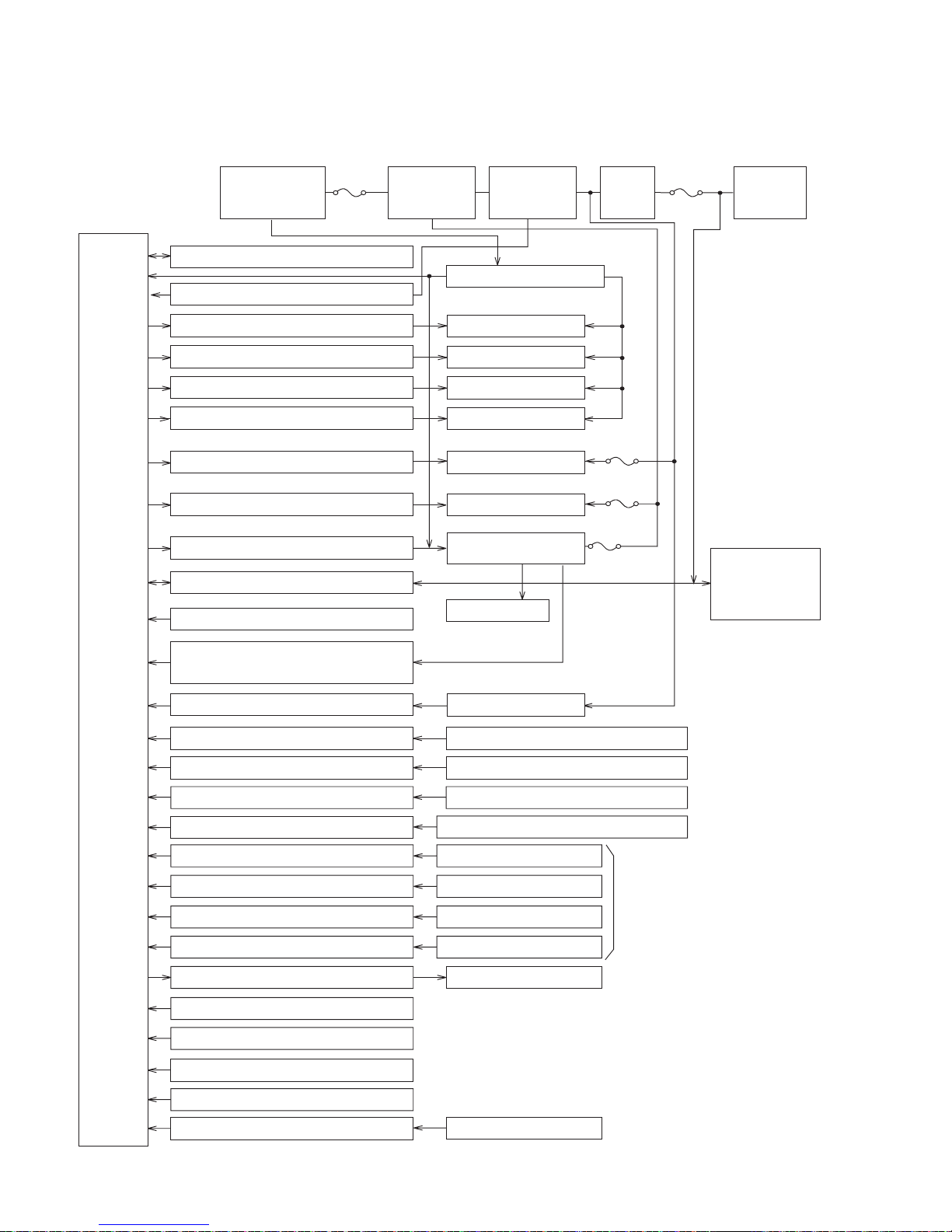
BLOCK DIAGRAM
CPU
2A
Power supply
circuit
CPU oscillator circuit
DC over voltage detection circuit
Expansion valve A drive circuit
Expansion valve B drive circuit
Expansion valve C drive circuit
Expersion valve D drive circuit
4-way valve relay drive circuit
Outdoor fan motor drive circuit
Power transistor module drive circuit
Serial I/O circuit
CPU reset circuit
DC overcurrent detection circuit /
Power transistor module overheat
Fuse
Smoothing
circuit
PFCM
module
DC power supply circuit
Expansion valve A
Expansion valve B
Expansion valve C
Expansion valve D
4-way valve
Outdoor fan motor
Power transistor
module
Compressor
Filter
circuit
3.15 A
Fuse
2 A
Fuse
20 A
Fuse
20 A
Fuse
AC power
Unit - unit wiring
(AC power and
serial signals)
AC overcurrent detection circuit
Compressor thermo circuit
Heat exchanger pipe thermo circuit
Outdoor temp. thermo. circuit Outdoor temperature thermistor (GN)
Suction pipe thermo circuit
Unit A thermo. circuit
Unit B thermo. circuit
Unit C thermo. circuit Thermistor unit C (BN)
Unit D thermo. circuit Thermistor unit D (YL)
LED drive circuit
DIP SW1
DIP SW2
Pump down switch circuit
Wire check switch circuit
Position detection circuit
Current transformer
Compressor thermistor (RED)
Heat exchanger pipe thermistor (OR)
Suction pipe thermistor (BK) CN8A
Thermistor unit A (BL)
Thermistor unit B (WT)
LED
Compressor
Suction thermistor
CN8M
CN8A
CN8A
CN8A
12
Page 13
AE-X4M30PU
FUNCTIONS
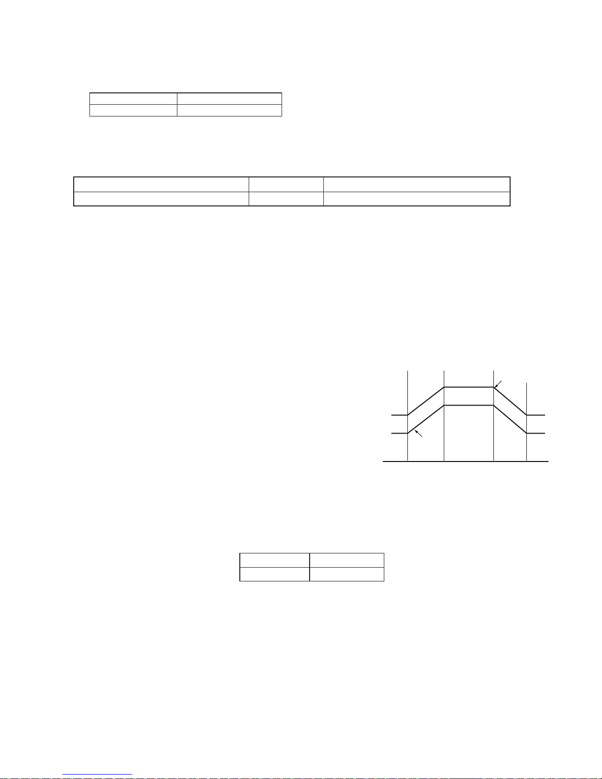
1. FREQUENCY CONTROL
1) AC current peak control
Cooling mode Heating mode
17.6A 18.4A
2) Prevention control of outdoor heat exchanger overheating
If the temperature of the outdoor heat exchanger exceeds the overheating prevention line 1or 2 during cooling, the operating
frequency is lowered by approximately 5 to 15Hz. After that, the frequency is lowered approximately 5Hz once every 60
seconds or approximately 15Hz once every 120 seconds. If the frequency is lowered to minimum frequency without the
temperature of the outdoor heat exchanger decreasing and this condition lasts for 1 minute, the compressor will be stopped.
Overheating Prevention line 1 129.2°F (54°C) Lower 5Hz once every 60 seconds
Overheating Prevention line 2 134.6°F (57°C) Lower 15Hz once every 120 seconds
3) Prevention control of compressor overheating
If the temperature of the compressor exceeds approximately 226.4°F (108°C), the operating frequency is lowered
approximately 5Hz. After that, the frequency is lowered approximately 5Hz once every 60 seconds. When the compressor
temperature drops below approximately 226.4°F (108°C), the frequency is raised approximately 5Hz once every 60 seconds,
and normal operation is restored. If the frequency is lowered to minimum frequency without the temperature of the compressor
decreasing, and this condition lasts for 1 minute, the compressor will be stopped.
4) Prevention control of indoor heat exchanger overheating
Two minutes after room several decrease If the temperature of any of indoor heat exchangers exceeds the overheating prevention
line 1 or 2 during heating, the operating frequency is lowered to minimum frequency. When the temperature of all of indoor heat
exchangers go below [the overheating prevention line 1 -45.5
60 seconds, and normal operation is restored. If the condition that the frequency is minimum lasts for 2 minutes, the compressor
will be stopped.
<When normal >
If the temperature of any of indoor heat exchangers exceeds the overheating prevention line 1 or 2 during heating, the operating frequency
is lowered by approximately 5 to 15Hz. After that, the frequency is
lowered approximately 5Hz once every 60 seconds or approximately 15Hz once every 90 seconds. When the temperature of all of
indoor heat exchangers go below [the overheating prevention line 1
-45.5
°
F(-7.5
°C)], the frequency is raised by approximately 5Hz once
every 60 seconds, and normal operation is restored. If the condition
that the frequency is minimum lasts for 2 minutes, the compressor will
be stopped.
2. OVER CURRENT PROTECTION
DC over current detection, AC over current detection To protect against over current due to sudden change in load, the
compressor is stopped if 25A DC is exceeded in the DC section. If the set value of AC current is exceeded in the AC section, the
compressor is stopped. 90 seconds after the compressor has been stopped, another starting try will be made. Three retries are
allowed. On the fourth retry, a complete stop request signal is sent to the indoor unit, and the outdoor unit will remain stopped until
the indoor operation is stopped. DC over current is detected by the power module. AC over current is detected by CT1, on the
outdoor PWB.
Cooling mode Heating mode
18A 18A
°
F(-7.5
°C)]
, the frequency is raised by approximately 5Hz once every
Overheating
131ºF (55°C)
143.6ºFº (62°C)
125.6ºF (52°C)
116.6ºF (47°C)
140.0ºF (60°C)
111.2ºF (44°C)
134.6ºF (57°C)
Overheating
prevention
line 1
900
138.2ºF (59°C)
When ON
(When OFF)
2200 5800 7200
prevention line 2
123.8ºF (51°C)
134.6ºF (57°C)
118.4ºF (48°C)
129.2ºF (54°C)
3. COMPRESSOR PROTECTION CONTROL
If the temperature of the compressor exceeds 235.4°F (113°C), the compressor is stopped. In this case, the outdoor fan is
not stopped until the temperature of compressor drops below 210.2°F (99°C). In 90 seconds after the compressor is stopped,
if the temperature is below 194°F (90°C), another starting try will be made. Three retries are allowed. On the fourth retry, a
complete stop request signal is sent to the indoor unit, and the outdoor unit will remain stopped until the indoor operation is
stopped.
4. POWER TRANSISTOR MODULE PROTECTION
If the temperature of the chips in the power transistor module exceeds 212°F (100°C), the compressor is stopped. In this
case, the outdoor fan is not stopped until the temperature of power module drops below 185°F (85°C). In 90 seconds after the
compressor is stopped, if the temperature is below 185°F (85°C), another starting try will be made. Three retries are allowed.
On the fourth retry, a complete stop request signal is sent to the indoor unit, and the outdoor unit will remain stopped until the
indoor operation is
stopped.
13
Page 14

AE-X4M30PU
5. SERIAL SIGNALS
Serial signals consist of all 96-bit signals. If the condition as outdoor unit unable to receive a serial signal from the indoor unit
continues for 30 seconds, it closes the expansion valve which corresponds to the room which can not be communicated. If all
indoor units can not communicate with the outdoor unit, the compressor is stopped.
6. THERMISTOR OPEN OR SHORT
When compressor, heat exchanger, outdoor thermistor, suction thermistor (CN8A) are in OPEN or SHORT condition, even if they are
in the condition which an operation signal is transmitted from indoors, the compressor will not start. If any suction thermistors (CN8M)
become OPEN or SHORT resistance, the protective procedure will work only for the cycle corresponding to the malfunctioning suction
thermistor.
7. MISWIRING CHECK
“Mis-wiring check” is conducted by detecting the indoor heat exchanger temp. For example, when the expansion valve for only room
A is open, and the wiring is correct, the indoor heat exchanger temp for room A will reduce. If the wiring is incorrect, the indoor heat
exchanger temp for a different room will reduce.
8. SAFETY TIME
When the unit is operated by the remote control after the breaker is turned on, the safety device of the compressor will work and the
compressor will not operate for 90 seconds.
9. PUMP DOWN SWITCH
When the PUMP DOWN SWITCH (SW1) is pressed for 5 seconds or more, the total A/C system will start its PUMP DOWN
automatically and the compressor frequency will be 40 Hz.
10. CONTROL OF COMPRESSOR AND EXPANSION VALVE
For 90 seconds after turning on the AC power, the compressor will not be activated even if indoor units request the compressor to
do so. If the compressor receives a request from one or more indoor units after 90 seconds have passed, it will be turned on and the
expansion valve corresponding to the requesting indoor unit will be opened. When the indoor unit of a room requests for the cooling
operation to the outdoor unit and it runs responding to the request, requests for the heating can’t be accepted if the indoor units in
other rooms send individual requests. If the indoor unit in another room sends a request for the heating operation, the operation lamp
and timer lamp of the indoor unit in that room start ashing in turn to inform that the unit is in the standby mode. If the operation in
one room is stopped while the indoor unit in another room is in the stand-by mode, the operation mode requested by the indoor unit
which is now in the stand-by mode will be accepted. At this time, the compressor will be temporarily stopped to switch the four- way
valve and restart after 90 seconds. During the cooling or dry operation, the expansion valve corresponding to the indoor unit that is not
running is closed. Therefore, the refrigerant will not ow into those units. However,if the heating operation is in progress, it is possible
that it ows into indoor units which are out of operation depending on the cycle conditions. As a result, the indoor exchanger may be
heated up even if it is not activated. This is not abnormal. When the operations in all rooms are stopped, the compressor is off and the
expansion valves in all rooms are fully opened.
11. DEFROST OPERATION
1) Overview
Defrosting begins during heating if the conditions for compressor
operation time and outdoor heat exchanger temperature are
met. When defrosting begins, the indoor and outdoor fans stop.
Defrosting stops when the temperature of the outdoor heat
exchanger goes above approximately 59°F
time exceeds 10 minutes.
2) Defrosting
If the compressor operation time is more than 20 minutes in
the heating mode and the outdoor air temperature and outdoor
heat exchange temperature satisfy the defrosting conditions, the
defrosting operation is started. When the defrosting operation
is started, the indoor fan s tarts to run intermittently. When the
outdoor heat exchanger temperature reaches approx. 59°F
or above or when the defrosting time exceeds 10 minutes, the
defrosting operation is quit.
(15°C)
or defrosting
(15°C)
Defrost
mask time
Heating
begins
Defrosting
Max. 10 min.
More than
20 min.
Defrost
mask time
Defrosting
Max. 10 min.
More than
20 min.
Defrost
mask time
More than
20 min.
Heating
operation
start
Defrosting
Max. 10 min.
Defrosting
Max. 10 min.
14
Page 15

AE-X4M30PU
3) During defrosting
When defrosting begins, the compressor stops. Approximately 1 minutes later, the compressor reactivates in the refrigeration
cycle, and the outdoor heat exchanger is defrosted. Each mode is as follows:
The outdoor fan is s topped.
The operating frequency is as shown in the table below.
The indoor fan is s topped.
All expansion valve are open. for 5 minutes 4800 rpm
ater that 4000 rpm
4) Defrost stop
When defrosting time exceeds 10 minutes When the temperature of the outdoor heat exchanger rises above approximately
(15°C)
Defrost stop is determined by either of the above conditions, and the compressor is s topped. At the same time, the outdoor
59°F°C
fan go ON. The compressor is reactivated in the heating cycle 1 minutes after it was stopped, and normal control resumes.
12. 5°F(-15°C) AUTO STOP FUNCTION
• During the heating operation, the unit will automatically stop when the
SELECT switch (DSW1)
outdoor temperature drops below 5°F(-15°C) to prevent the outdoor unit
from the damage caused by the freezing of the drained water. The unit
will stop its operation for 4 hour and then resume the operation when the
LED1A
outdoor temperature rises above 7°F(-13.9°C).
• To inactivate this function, slide the SELECT switch(DSW1) #1 to OFF side.
DSW1
LED1B
LED1C
1
2
OFF
ON
LED1D
13. Preheat
When heating is stopped, applying a small amount of voltage to the compressor to make heating start more quickly.
The preheat function will active according to outdoor temperature and compressor temperature.
To inactivate this function, slide the SELECT switch (DSW1) #2 to OFF side.
DSW1
1
2
OFF
ON
SELECT
DSW1
1
2
OFF
ON
PUMP DOWN
SW1
WIRE CHECK
SW2
15
Page 16

AE-X4M30PU
TROUBLE SHOOTING GUIDE
SELF-DIAGNOSIS FUNCTION
NOTE: WHEN TURN ON THE POWER SUPPLY AGAIN, WAIT MORE THAN 10 MINUTES AFTER TURN OFF TO PRE-
VENT ELECTRIC SHOCK.
Indoor unit
• To display the self-diagnosis, hold down the AUX button for over 5 seconds on the indoor unit when the indoor unit is not operating.
• The operation lamp (green), timer lamp (orange) and Plasmacluster lamp (blue) ash to indicate the information of malfunction.
• If the power cord is unplugged or the circuit breaker is turned off, the self-diagnosis memory is lost.
AUX
Plasmacluster lamp (Blue)
Operation lamp (Green)
Timer lamp (orange)
<Display of self-diagnosis result>
The operation lamp (green) and the Plasmacluster lamp (blue) ash in synchronization with the timer lamp (orange).
Timer lamp (1 cycle)
1st 2nd 3rd 4th 5th
1-second
ON
1-second
ON
1-second
ON
1-second
ON
1-second
ON
ON
OFF
ON
OFF
1-second
OFF
0.5-second
ON
0.5-second
ON
5-second OFF
0.5-second ON0.5-second
ON
1-second
OFF
1-second
OFF
1-second
OFF
Outdoor unit
• The self-diagnosis is indicated the error information by ashing LED1 on the outdoor unit.
• The self-diagnosis of outdoor unit is displayed for about 3-10 minutes. Then, the LED1 returns to normal display.
Normal
LED1
SELECT
LED1A
LED1B
LED1C
LED1D
DSW1
1
2
OFF
PUMP DOWN
WIRE CHECK
SW1
SW2
ON
2-time
3-time
16
ON
OFF
ON
OFF
0.5-second
0.5-second
ON
0.5-second
0.5-second
ON
0.5-second
OFF
0.5-second
OFF
0.5-second
OFF
OFF
0.5-second
OFF
0.5-second
2-time
0.5-second ON0.5-second
ON
OFF
0.5-second
OFF
0.5-second
3-time
0.5-second ON0.5-second ON0.5-second
ON
OFF
0.5-second
OFF
0.5-second
ON
ON
Page 17

<INDOOR UNIT> ○:1-second ON / 1-second OFF
Problem
symptom
Normal
condition
Indoor and
outdoor units
do not operate.
Indoor and
outdoor units
do not
operate.
Indoor unit
operates.
Outdoor
unit does
not operate
temporarily
Indoor and
outdoor
units do not
operate.
Indoor and
outdoor
units do not
operate.
Indoor and
outdoor
units do not
operate.
Outdoor unit
indication
(LED1)
Normal
blinking
1 time O O O O O Timer (Orange) 1 0 Outdoor unit
2 time
3 time O O O O O Timer (Orange) 3 0 Temporary
5-time O O O O O Timer (Orange) 5 0 Outdoor unit
O O O O O Timer (Orange) 0 0 Normal
O O O O O Timer (Orange) 1 Outdoor temperature
O O O O O Timer (Orange) 2 Suction thermistor
O O O O O Timer (Orange) 3 Suction thermistor
O O O O O Timer (Orange)
O O O O O Timer (Orange) 1 Compressor
O O O O O Timer (Orange) 2 Outdoor unit heat
O O O O O Timer (Orange) 3 Indoor unit heat
O O O O O Timer (Orange) 4 IPM high
O O O O O Timer (Orange) 5 IPM high
O O O O O Timer (Orange) 7 High pressure error
O O O O O Timer (Orange) 1 Outdoor temperature
O O O O O Timer (Orange) 2 Suction thermistor
O O O O O Timer (Orange) 3 Suction thermistor
O O O O O Timer (Orange) 4 Discharge thermistor
O O O O O Timer (Orange) 5 Heat sink thermistor
Indoor unit
→
O Operation (green)
O Operation (green)
O Plasmacluster (blue)
O Operation (green)
O Plasmacluster (blue)
O Operation (green)
O O Plasmacluster (blue)
O Operation (green)
O Operation (green)
O Plasmacluster (blue)
O Operation (green)
O Plasmacluster (blue)
O Operation (green)
O O Plasmacluster (blue)
O Operation (green)
O Plasmacluster (blue)
O Operation (green)
O O Plasmacluster (blue)
O Operation (green)
O O O Plasmacluster (blue)
O O Operation (green)
O O Operation (green)
O O Operation (green)
O Plasmacluster (blue)
O O Operation (green)
O Plasmacluster (blue)
O O Operation (green)
O O Plasmacluster (blue)
O O
O Plasmacluster (blue)
O O Operation (green)
O O Plasmacluster (blue)
Lamp Main Sub Main Sub
Operation (green)
Plasmacluster (blue)
Plasmacluster (blue)
Plasmacluster (blue)
Plasmacluster (blue)
Plasmacluster (blue)
Operation (green)
Malfunction
No.*
2 0 Cycle
Content of diagnosis
thermistor
short-circuit
temperature
stop
thermistor
open-circuit
Heat exchanger
thermistor short
circuit error
thermistor short
circuit error
short circuit error
(for unit A, B, C, D)
short circuit error
Compressor high
temperature error
discharge overheat.
exchanger overheat.
exchanger overheat.
temperature error
temperature error
Temporary stop due
to low temperature
of out door
Heat exchanger
thermistor open
circuit error
thermistor open
circuit error
open circuit error
(for unit A, B, C, D)
open circuit error
open circuit error
open circuit error
Check point Action
1) Measure the resistance
of the outdoor unit
thermistors.
(TH2-4, 6-8: Approx. 4.4kΩ at
77°F(25°C))
2) Check the lead wire of the
outdoor unit thermistor
for torn sheath and
shortcircuit.
3) 1) 2):Normal
1) Check the outdoor unit air
outlet for blockage.
2) Check if the power supply
voltage is AC 230V at full
power.
3) Check the pipe connections
for refrigerant leaks.
4) Measure resistance of the
outdoor unit compressor
thermistor.
(TH1:Approx.50kΩ at 77°F(25°C)
5) Check the expansion valve
for proper operation.
(Temporary stop for cycle
protection)
(Temporary stop for cycle
protection)
(Temporary stop for cycle
protection)
Measure resistance of the
heat-sink thermistor.
Replace the outdoor unit
control PCB assembly.
Check pressure sensor -
(Temporary stop for cycle
protection)
1) Check connector CN8A
and CN8C of the outdoor
unit thermistor for secure
installation.
2) Measure resistance of
outdoor thermistors TH14, 6-8.
3) Check the lead wires of
thermistors TH1- 4, 6-8
on the outdoor unit control
PCB for open-circuit.
4) 1) 2) 3):Normal
1) Replace the outdoor unit
thermistor assembly.
2) Replace the outdoor unit
thermistor assembly.
3) Replace the outdoor unit
control PCB assembly.
1) Ensure unobstructed air
ow from the outdoor
unit air outlet.
2) Connect power supply
of proper voltage.
3) Charge the specied
amount of refrigerant.
4) Replace the outdoor unit
compressor thermistor
assembly.
5) Replace the expansion
valve coil, expansion
valve or outdoor unit
control PCB assembly.
If the temperature of
outdoor is not lower than
5°F(-15°C), check the
outdoor temp. thermistor.
1) Correct the installation
2) Replace the outdoor unit
thermistor assembly.
3) Replace the outdoor unit
thermistor assembly.
4) Replace the outdoor unit
control PWB assembly.
AE-X4M30PU
-
-
-
-
-
17
Page 18

AE-X4M30PU
Problem
symptom
Indoor and
outdoor
units do not
operate.
Indoor and
outdoor
units do not
operate.
Indoor and
outdoor
units do not
operate.
Indoor and
outdoor
units do not
operate.
Indoor and
outdoor
units do not
operate.
Indoor and
outdoor
units do not
operate.
Outdoor unit
indication
(LED1)
6-time O O O O O Timer (Orange) 6 0 Outdoor unit
O O O O O Timer (Orange) 1 IPM pin level error Check the IPM is attached
7-time O O O O O Timer (Orange) 7 0 Outdoor unit
O O O O O Timer (Orange) 1 AC current error
O O O O O Timer (Orange) 2 AC maximum current
O O O
8-time O O O O O Timer (Orange) 8 0 Abnormal
9-time O O O O O Timer (Orange) 9 4 Cycle
10-time O O O O O Timer (Orange) 10 2 EEPROM
11-time O O O O O Timer (Orange) 11 0 Outdoor unit
O O O O O Timer (Orange) 1 Outdoor unit DC fan
O O O O O Timer (Orange) 2 Outdoor unit DC fan
O O O O O Timer (Orange) 3 Detection error of DC
O O O O O Timer (Orange) 4 Detection error of
O O O O O Timer (Orange) 5 Outdoor unit DC fan
Indoor unit
→
O O Operation (green)
O O Operation (green)
O Plasmacluster (blue)
O O O Operation (green)
O O O Operation (green)
O Plasmacluster (blue)
O O O Operation (green)
O Plasmacluster (blue)
O O Timer (Orange) 3 AC current
O O O Operation (green)
O O Plasmacluster (blue)
O Operation (green)
O O Operation (green)
O Plasmacluster (blue)
O O Operation (green)
O Plasmacluster (blue)
O O O Operation (green)
O O O Operation (green)
O Plasmacluster (blue)
O O O Operation (green)
O Plasmacluster (blue)
O O O Operation (green)
O O Plasmacluster (blue)
O O O Operation (green)
O Plasmacluster (blue)
O O O Operation (green)
O O Plasmacluster (blue)
Lamp Main Sub Main Sub
Plasmacluster (blue)
Plasmacluster (blue)
Plasmacluster (blue)
Plasmacluster (blue)
Malfunction
No.*
DC Current
AC Current
wire check
temperature
error
DC fan
Content of diagnosis
DC over current
error
AC over current error 1) Ensure unobstructed air
when OFF
error
deciency error
Abnormal wire check
error
4 way valve error or
Gas leak error
EEPROM (outdoor)
data error
Outdoor unit DC fan
rotation error
drive IC error
lock error
fan negative rotation
before compressor is
driven
inverter current for
DC fan
open connector error
Go to “DC Over Current Error (6-0 error)”.
correctly to the outdoor unit
IPM PWB.
ow from the outdoor unit
air outlet.
2) Check the outdoor unit fan
motor.
1) IPM continuity check 1) Replace the outdoor
1) Ensure unobstructed air
ow from the outdoor unit
air outlet.
2) Check the outdoor unit fan
motor.
1) Replace the outdoor unit
control PCB assembly.
2) Charge the specied
amount of refrigerant.
3) Correct refrigerant clogs.
(Stop valve, pipe, expansion valve)
1) Check the expansion valve.
(unit A - C)
2) Are four expansion valves
connected by mistake.
3) Check the wiring between
units.
1) Check the unit thermistor
TH2 (exchange) and
TH3 (pipe temperature)
are installed in correct
portions.
2) Check if the refrigerant
volume is abnormally low.
3) Check the 4-way valve for
proper operation.
- Replace the outdoor unit
1)
Check connector CN3 of the
outdoor unit DC fan motor
for secure installation.
2) Check the outdoor unit fan
motor for proper rotation.
3) Check fuse FUSE5.
4) Outdoor unit control PWB
1) Check if the fan IPM
terminal resistance values
are uniform.
2) Outdoor unit fan motor
continuity check.
1) Check the outdoor unit fan
motor for proper rotation.
2) 1): Normal
(Temporary stop for DC fan
circuit protection)
- Replace the outdoor unit
Check connector CN3 of the
1)
outdoor unit DC fan motor
for secure installation.
2) No abnormality found in
above inspection 1).
Check point Action
Replace the outdoor unit
IPM PWB assembly.
1) Ensure unobstructed air
ow from the outdoor
unit air outlet.
2) Check the outdoor unit
fan motor.
IPM PWB
1) Ensure unobstructed air
ow from the outdoor
unit air outlet.
2) Check the outdoor unit
fan motor.
1) Replace the outdoor unit
control PCB assembly.
2) Charge the specied
amount of refrigerant.
3) Correct refrigerant clogs.
(Stop valve, pipe,
expansion valve)
1) Replace the outdoor
control board assembly.
2) Reattach
3) Check the wiring
between units.
1) Correct the installation.
2) Change the specied
amount of refrigerant.
3) Replace the 4-way
valve.
control PWB assembly.
1) Correct the installation.
2) Replace the outdoor unit
fan motor.
3) Replace the outdoor unit
control PWB assembly.
4) Replace the outdoor unit
control PWB assembly.
1) Replace the outdoor unit
control PWB assembly.
2) Replace the outdoor unit
fan.
1) Replace the outdoor unit
control PWB assembly.
2) Replace the outdoor unit
fan.
-
control PWB assembly.
1) Correct the installation.
2) Replace the outdoor unit
control PWB assembly.
18
Page 19

AE-X4M30PU
Problem
symptom
Indoor and
outdoor
units do not
operate.
Indoor and
outdoor
units do not
operate.
Indoor and
outdoor units
operate.
Indoor and
outdoor
units do not
operate.
Indoor unit
operates.
Outdoor unit
does not
operate.
Indoor unit
operates.
Outdoor unit
does not
operate.
Indoor and
outdoor
units do not
operate.
Indoor and
outdoor
units do not
operate.
Indoor and
outdoor
units do not
operate.
Outdoor unit
indication
(LED1)
12-time O O O O O Timer (Orange) 12 0 Thermal fuse
13-time O O O O O Timer (Orange) 13 0 DC
O O O O O Timer (Orange) 1 Compressor rotation
O O O O O Timer (Orange) 2 Compressor rotation
O
14-time O O O O O Timer (Orange) 14 0 Outdoor unit
O O O O O Timer (Orange) 1 PFC Module clock
O O O O O Timer (Orange) 2 PFC Module low
O O O O O Timer (Orange) 4 PFC Module error
Lighting or
OFF
Lighting or
OFF
Normal
blinking or
OFF
Normal
blinking or
OFF
O O O O O Timer (Orange) 17 0 Wiring
O O Operation (green)
O O O O O Timer (Orange) 18 0 Wiring
O O Operation (green)
O O O O O Timer (Orange 1 Check the wiring between
O O Operation (green)
O O O O O Timer (Orange) 19 0 Indoor unit
O O O Operation (green)
O O O O O Timer (Orange) 20 0 Indoor unit
O O Operation (green)
Indoor unit
→
O O Operation (green)
O O O Operation (green)
O O O Operation (green)
O Plasmacluster (blue)
O O O Operation (green)
O Plasmacluster (blue)
O O O O Timer (Orange) 3 Detection error of
O O O Operation (green)
O O Plasmacluster (blue)
O O O Operation (green)
O O O Operation (green)
O Plasmacluster (blue)
O O O Operation (green)
O Plasmacluster (blue)
O O O Operation (green)
O Plasmacluster (blue)
O Plasmacluster (blue)
Lamp Main Sub Main Sub
Plasmacluster (blue)
Plasmacluster (blue)
Plasmacluster (blue)
Plasmacluster (blue)
Plasmacluster (blue)
Plasmacluster (blue)
Plasmacluster (blue)
Malfunction
No.*
Content of diagnosis
in terminal
board
compressor
Active lter
between
units
between
units
fan
control PCB
Check point Action
Thermal fuse error
in terminal board (for
power supply)
Compressor startup
error
error.
(at120C energizing)
error
(at 180C energizing)
inverter current
PFC Module over
voltage error
error
voltage error
Serial opencircuit 1) Check the wires between
Serial opencircuit Check the wiring between
Indoor unit fan error 1)
EEPROM data error (EEPROM read data error) Replace the indoor unit
1) Check the thermal fuse in
terminal board (for Power
supply)
2) Check connector CN5 of
the outdoor unit.
3) 1) 2): Normal
1) Check the colors (red,
white, orange) of the compressor cords for proper
connection.
(PWB side, compressor side)
2) Check if the IPM terminal
resistance values are
uniform.
3) Check if outdoor main
relay (MRY1) turns on
and voltage of both end of
the condenser (C10) has
become DC290-330V.
4) 1) 2) 3) : Normal
Check the circuit of detection
of inverter current.
1) Check the connector of
PFCM for secure installation.
2) Check the AC power supply
voltage for uctuation.
3) 1),2) Normal
units.
2) Check voltage between N
and 1 the indoor/outdoor
unit terminal boards.
Check the outdoor unit fuse.
3)
4) Check 15-V,13-V and 5-V
voltages on the PCB.
Check resistance between
IPM terminals.
5) Check pins No.5 and 8
of connector CN3 of the
outdoor unit fan motor for
shortcircuit.
6) Outdoor unit control PCB.
units.
units.
Check the indoor fan motor for
proper rotating operation.
(Check fan lock.)
2) Check the lead wire of the
indoor fan motor for opencircuit.
3) Check connector ofthe
indoor unit fanmotor for
secureinstallation.
4) 1) 2) 3): Normal
1) Replace terminal board
for Power supply.
2) Correct the installation.
3) Replace the outdoor unit
control PCB assembly.
1) Correct the installation.
(U: Red, V: White, W:
Orange)
2) Replace the outdoor unit
control PWB assembly.
3) Replace the outdoor unit
control PWB assembly.
4) Replace the compressor.
Replace the outdoor unit
control PWB assembly.
1) Correct the installation.
2) Connect stable power
supply.
3) Replace the outdoor unit
PFCM PWB or control
PCB assembly.
1) Connect stable power
supply.
Correct the wiring.
2) Replace the outdoor unit
control PWB assembly.
3) Replace the fuse/outdoor unit control PWB
assembly.
4) Replace the outdoor unit
control PWB assembly.
5) Replace the outdoor unit
fan motor.
6) Replace the outdoor unit
control PWB.
Correct the wiring.
Correct the wiring.
1) Replace the indoor fan
motor.
2) Replace the indoor fan
motor.
3) Correct the installation
of the indoor fan motor
connector.
4) Replace the indoorunit
control PCB.
control PWB.
19
Page 20

AE-X4M30PU
*Remark
The malfunction No. is calculated using the following way.
Example)
Lamp Calculation Main Sub
Indoor unit lamp
Timer (orange) O O O O O
Operation (green) O O 4+1=5 5
Plasmacluster (blue) O 2 2
→
16 8 4 2 1
k
Ω
100
80
Heat exchange thermistor
TH2 (Orange), TH3 (Black)
77ºF(25ºC) resistance 4.431 kΩ
60
40
Resistance
20
0
-10 0 10 20 30 40
Figure 1 Temperature properties of indoor thermistors
Thermistor
Room temperature
Heat exchange
Pipe temperature
To measure the resistance, first remove
the soldering as shown at right.
Room temperature
thermistor TH1 (Yellow)
77ºF(25ºC) resistance 10 kΩ
Signal
TH1
TH2
TH3
Color
Yellow
Orange
Black
ºC
Room temperature
thermistor TH1 (CN2 3 - 4 )
Heat exchange
thermistor TH2 (CN2 1 - 2 )
Pipe temperature
thermistor TH3 (CN2 5 - 6 )
CN2
1
6
Tester
CAUTION: When attaching or removing the board
When operating only the outdoor unit (cooling 40 Hz fixed mode) To make only the outdoor unit run in cooling
mode, and apply a voltage of 230V AC to L1 and L2 on the terminal board and push the pump down switch (SW1).
(Avoid operating the outdoor unit alone for long periods of time.)
from Main PWB
BCN13
from Main PWB BT12 (Blue)
from Main PWB BT11 (Yellow)
from PFC coil
from Main PWB
MRY1 OUT (Black)
from Main PWB T15 (Gray)
from PFC coil
20
Page 21

Figure 2 Temperature properties of outdoor thermistors
TH1 : Compressor thermistor (CN8A 1 - 2 )
TH2 : Heat exchanger pipe thermistor (CN8A 3 - 4 )
TH3 : Outdoor temp. thermistor (CN8A 5 - 6 )
TH4 : Suction thermistor (CN8A 7 - 8 )
TH6 : Thermistor unit A (CN8M 1 - 2 )
TH7 : Thermistor unit B (CN8M 3 - 4 )
TH8 : Thermistor unit C (CN8M 5 - 6 )
TH9 : Thermistor unit D (CN8M 7 - 8 )
AE-X4M30PU
1
9
Connector
CN8A
1
Connector
CN8M
10
Resistance ( )
500k
400k
300k
200k
100k
0
(-20) (0) (20) (60) (80)(100) (120)
25ºC resistance
50.0 kΩ
6.2kΩ
-4 32 68 140 176 212 248
Temperature ºF (ºC) Temperature ºF (ºC)
4.5kΩ
TH-1
3.3kΩ
2.5kΩ
1.9kΩ
40k
30k
20k
Resistance ( )
10k
0
-4 32 68 140
(-20) (0) (20) (60)(40)
Thermistor No. Connector Color Connector pin
Compressor thermistor TH1 CN8A Red No. 1 to 2
Heat exchanger pipe thermistor TH2 CN8A Orange No. 3 to 4
Outdoor temp. thermistor TH3 CN8A Green No. 5 to 6
Suction thermistor TH4 CN8A Black No. 7 to 8
Thermistor unit A (suction) TH6 CN8M Blue No. 1 to 2
Thermistor unit B (suction) TH7 CN8M White No. 3 to 4
Thermistor unit C (suction) TH8 CN8M Brown No. 5 to 6
Thermistor unit D (suction) TH9 CN8M Yellow No. 7 to 8
1. How to distinguish the defective parts
1) When all rooms are not cooled
32ºF(0ºC)
14.5 kΩ
77ºF(25ºC)
4.431 kΩ
resistance
resistance
TH2 - TH4
TH6 - TH9
104
Yes
The cooling cycle is abnormal.
Check the pressure.
Are the timer lamps of the indoor units in all rooms flashing ?
No
Press the OPERATION button to start
operating the air-conditioner.
(One-room operation ON)
(Set the cooling mode to 61ºF(16ºC))
Is the compressor of the outdoor
unit operating ?
No
Are the timer lamps of the indoor
units in all rooms flashing ?
No
Check that the power between
the terminal board "L1" and "L2"
of the indoor unit is AC 230V,
60Hz.
Repair the wiring between the
units.
Yes
Yes
Check the failure symptom with
the failure diagnosis mode.
A
TO
(Check the failure with
the outdoor unit.)
21
Page 22

AE-X4M30PU
Yes
Fix the Power factor
module with screws
No
Power factor module (PFCM) error
Open circuit of serial signal line
Abnormal AC current
Is the Power factor module in a
state of flaoting from the heatsink?
Short circuit of serial signal line
Is the winding of the current
transformer broken ?
secuerly
Yes
Are 4 lamps
switched off ?
Yes
Yes
No
Is the resistance value among
the terminal of the Power fac-
tor module (PFCM) 0 ?
No
Yes
Is CN6 connected ?
No
Yes
Is the resistance value of the
winding in the current trans-
former ? (720 )
Replace the Power
factor module (PFCM)
Connect CN6.
Check the voltage (5V).
Replace the current
transformer
Yes
Fix the IPM PWB with
screws securely.
No
Power module PWB
(IPM) abnormality
No
Rotation error of
AC overcurrent
A
Overheat of the compressor
Is CN16 connected ?
the compressor
Is the IPM PWB in a
state of floating from
the heat sink ?
Connect CN16
Yes
Check the voltage
(18V).
No
Inspect the compres-
The cycle is abnormal.
Yes
No
Is the outdoor fan
motor operating ?
Yes
No
Yes
P - U, N - U
P - V, N - V
nals of the IPM PWB 0 ?
No
Is CN3A connected ?
P - W, N - W
Connect CN3
Yes
Is each of the resistance
values among the termi-
sor, heat exchanger
and piping.
Is each of the resist-
P - U, N - U
P - V, N - V
ance values among
the terminals of the
Replace the IPM PWB
Check the FUSE 5
P - W, N - W
IPM PWB 0 ?
Yes
Is the resistance value
between 5 and 8
Replace the IPM PWB.
No
The compressor is abnormal.
Replace the fan motor.
No
of fan motor 0?
Replace the Compressor.
Yes
No
Check the voltage
(15V).
Replace the outdoor control PWB.
Open circuit of the
outdoor thermistor
Is the resistance
value of the ther-
mistor for the com-
pressor (TH1), heat
ex-changer (TH2)
or outdoor temper-
ature (TH3) or suc-
tion (TH4, TH6-9)
correct?
22
No
Replace the
thermistor.
Page 23

2) When one room is not cooled (other rooms are cooled)
AE-X4M30PU
Is the timer lamp of the
indoor unit in the room
not cooled flashing ?
No
Press the OPERATION button
to start operating the air-conditioner.
(Set the cooling mode to
61ºF(16ºC))
Is the timer lamp of the
indoor unit in the room
not cooled flashing ?
No
Check that the power
between the terminal
No
board "L1" and "L2" of the
indoor unit is AC 230V.
Yes
Replace the indoor
control PWB.
Yes
Check the failure symptom
Yes
with the failure diagnosis
mode.
Short circuit of the thermistor error
Open circuit of the thermistor error
Is the resistance value of the thermistor for
(TH7), UNIT C (TH8) or UNIT D
(TH9)
UNIT A (TH6), UNIT B
No
Replace the thermistor.
Yes
Repair the wiring
between the units.
Replace the outdoor control
or the expansion valve
or the expansion valve
or the expansion valve
or the expansion valve
Abnormal fan motor of
indoor unit
Is the resistance value of the
winding in the fan motor ?
(Between 1 and 3 of CN1)
Yes
The thermal fuse is blown.
The motor is locked.
Replace the indoor fan motor.
PWB
(UNIT A)
(UNIT B)
(UNIT C)
(UNIT D)
Open circuit of serial signal line
Short circuit of serial signal line
No
Is the wiring between the
units connected by
mistake or broken ?
Yes
Repair the wiring
between the units.
Replace the indoor control PWB.
No
23
Page 24

AE-X4M30PU
3) When all rooms are not heated
The heating cycle is normal.
Does the air get cooler in the
cooling operation mode?
Refer to 1 All rooms are
not cooled.
Check the four-way valve.
Yes
Has the cycle been switched?
Is AC230V applied between
the connector(CN4) 1 and 3
of the 4-way valve ?
No
No
Yes
Press the ON switch on the remote
control to run the air conditioner.
Set the temperature to 86ºF(30ºC)
in the heating mode and start
operation.
No
Yes
Is the outdoor compressor running?
No
To
A
Yes
Replace the 4-way valve.Pressure check
24
Page 25

PROTECTIVE FUNCTIONS AND OPERATIONS
AE-X4M30PU
NO. Function
1 DC over current
2 AC over current
Compressor over-
3
heat prevention
control
Compressor high
4
temperature error
Outdoor heat
exchanger over-
5
heat prevention
control
6 Thermistor short
7 Thermistor open
AC abnormal cur-
8
rent
9 Serial signal error
Miswiring check
10
error
Indoor heat
exchanger over-
11
heat prevention
control
Description Detection time Restart condition
Compressor is stopped if a current approxi-
mately 25A or more ows in the power transistor
module.
Lowers the operating frequency if the compres-
sor AC current exceeds set value(19.3). Stops
the compressor if the current exceeds at minimum frequency.
Lowers the operating frequency if the temperature of the compressor thermistor (TH1) rises
above 226.4°F (108°C). Compressor is stopped
if the thermistor stays above 226.4°F (108°C) for
2 minutes at minimum frequency.
Compressor is stopped if the compressor thermistor is above 235.4°F (113°C) (Or when TH1
shorts)
Lowers the operating frequency if the temperature of the outdoor heat exchanger rises above
134.6°F(57°C) during cooling. Stops the compressor if the temperature stays above 134.6°F
(57°C) for 2 minutes at minimum frequency
Compressor is stopped, if heat exchanger or
outdoor thermistor shorts. Close the expansion
valve of the corresponding room, if some suction
thermistor shorts.
Compressor is stopped, if compressor or heat
exchanger or outdoor thermistor opens.
Close the expansion valve of the corresponding
room, if some suction thermistor shorts or opens.
Compressor is stopped, if the operating frequency is above 70Hz and the compressor current is
below 0.8A.
INDOOR
If open, while timer LED blinks, operation is con-
tinued. If short, operation is continued.
OUTDOOR
Loses the expansion valve of the corresponding
room if the outdoor unit does not receive a serial
signal from one or more indoor unit for 30 seconds.
Compressor is stopped, if the out-door unit does
not receive a serial signal from all indoor units.
Compressor is stopped, and miswiring check
operation ends.
Lowers the operating frequency if the temperature of any of indoor heat exchanger rises high
temperature during heating.
Stops the compressor if the temperatures rays
high for 2 minutes at minimum frequency.
Operation
During compressor
operation
During compressor
operation
During compressor
operation
During compressor
operation
During compressor
operation
When the room is
activated turns ON
and the compressor starts.
When the room
turns ON and the
compressor starts.
During compressor
operation
During operation
During miswiring
operation
During compressor
operation
Automatically restarts after
safety time (180 seconds)
Automatically restarts after
safety time (180 seconds)
Automatically restarts after
safety time (180 seconds)
Automatically restarts when
thermistor (TH1) temperature
falls below 210.2°F (99°C)
(approximately 30 minutes)
Automatically restarts after
safety time (180 seconds)
Operation OFF 1 time Yes Yes
Operation OFF 1 time Yes Yes
Automatically re-starts after
safety time.(180 sec.)
Automatically re-starts as soon
as the serial communication
becomes possible.
Miswiring check operation will
not re-start automatically.
Automatically re-starts after
safety time.(180 sec.)
4 times Yes Yes
4 times Yes Yes
No limit No No
4 times Yes Yes
No limit No No
4 times Yes Yes
No limit Yes Yes
4 times Yes Yes
No limit No No
Power factor mod-
12
ule error
DC Compressor
13
rotation error
IPM overheat pre-
vention control.
14
IPM high temperature error
When a power factor module error input is
detected.
In the case that the feed back signal from the
compressor is not input or abnormal.
Lowers the operating frequency if the temperature of IPM rises high temperature.
Stops the compressor if the temperatures rays
high for 2 minutes at minimum frequency.
During compressor
operation
During compressor
operation
During compressor
operation
25
Automatically re-starts after
safety time.(180 sec.)
Automatically re-starts after
safety time.(180 sec.)
Automatically restarts after
safety time.(180 sec.)
4 times Yes Yes
8 times Yes Yes
No limit No No
Page 26

AE-X4M30PU
1. Refrigeration Cycle
REFRIGERATION CYCLE
UNIT D *
(3)
UNIT C *
(3)
UNIT B
(3)
UNIT A
(3)
* 15K, 18K can’t be connected.
2. Flow of refrigerant
Heat exchanger
Heat exchanger
Heat exchanger
Heat exchanger
INDOOR UNIT
Expansion valve D
Expansion valve C
Expansion valve B
Expansion valve A
STOP valve (Liquid)
(1)
Compressor
(4)
Accumulator
STOP valve (Gas)
OUTDOOR UNIT
4-way valve
(AE-X4M30PU)
(2)
Heat exchanger
UNIT D *
UNIT C *
UNIT B
UNIT A
INDOOR UNIT
Cooling heating
* 15K, 18K can’t be connected.
OUTDOOR UNIT (
AE-X4M30PU
)
26
Page 27

3. Cycle temperature and pressure in stop valve
Running unit No.
AY-XPC09PU &
AY-XPC07PU &
AY-XPC07PU &
AY-XPC07PU
AY-XPC18PU
(1 unit only on
operation)
AY-XPC15PU
(1 unit only on
operation)
AY-XPC12PU
(1 unit only on
operation)
AY-XPC09PU
(1 unit only on
operation)
AY-XPC07PU
(1 unit only on
operation)
Stop valve pressure (gas side) 136 psig 164 psig 345 psig 253 psig
Frequency 100Hz 58Hz 118Hz 50Hz
Stop valve pressure (gas side) 103 psig 132 psig 465 psig 355 psig
Frequency
Stop valve pressure (gas side) 107 psig 134 psig 467 psig 349 psig
Frequency 61Hz 34Hz 80Hz 49Hz
Stop valve pressure (gas side) 121 psig 149 psig 485 psig 326 psig
Frequency 49Hz 27Hz 55Hz 40Hz
Stop valve pressure (gas side) 133 psig 157 psig 485 psig 346 psig
Frequency 36Hz 20Hz 70Hz 40Hz
Stop valve pressure (gas side) 144 psig 162 psig 419 psig 352 psig
Frequency 28Hz 17Hz 55Hz 40Hz
(1) 186 ºF (85℃ ) 156 ºF (69℃ ) 158 ºF (70℃ ) 112 ºF (44℃ )
(2) 103 ºF (40℃ ) 100 ºF (38℃ ) 30 ºF (-1℃ ) 36 ºF (2℃ )
(3) 58 ºF (14℃ ) 62 ºF (16℃ ) 87 ºF (31℃ ) 79 ºF (26℃ )
(4) 64 ºF (18℃ ) 71 ºF (22℃ ) 32 ºF (0℃ ) 42 ºF (5℃ )
(1) 195 ºF (90℃ ) 167 ºF (75℃ ) 193 ºF (90℃ ) 157 ºF (70℃ )
(2) 99 ºF (37℃ ) 100 ºF (38℃ ) 39 ºF (4℃ ) 38 ºF (3℃ )
(3) 46 ºF (8℃ ) 53 ºF (12℃ ) 106 ºF (41℃ ) 90 ºF (32℃ )
(4) 53 ºF (12℃ ) 64 ºF (18℃ ) 35 ºF (2℃ ) 39 ºF (4℃ )
(1) 188 ºF (87℃ ) 165 ºF (74℃ ) 192 ºF (89℃ ) 155 ºF (69℃ )
(2) 99 ºF (37℃ ) 101 ºF (38℃ ) 39 ºF (4℃ ) 37 ºF (3℃ )
(3) 49 ºF (9℃ ) 55 ºF (13℃ ) 112 ºF (45℃ ) 91 ºF (33℃ )
(4) 56 ºF (14℃ ) 66 ºF (19℃ ) 36 ºF (2℃ ) 39 ºF (4℃ )
(1) 166 ºF (74℃ ) 149 ºF (65℃ ) 167 ºF (75℃ ) 124 ºF (51℃ )
(2) 95 ºF (35℃ ) 95 ºF (35℃ ) 38 ºF (3℃ ) 37 ºF (3℃ )
(3) 54 ºF (12℃ ) 59 ºF (15℃ ) 103 ºF (40℃ ) 78 ºF (25℃ )
(4) 56 ºF (14℃ ) 68 ºF (20℃ ) 38 ºF (3℃ ) 45 ºF (7℃ )
(1) 152 ºF (67℃ ) 145 ºF (63℃ ) 181 ºF (83℃ ) 135 ºF (57℃ )
(2) 95 ºF (35℃ ) 95 ºF (35℃ ) 35 ºF (2℃ ) 37 ºF (3℃ )
(3) 55 ºF (13℃ ) 60 ºF (15℃ ) 106 ºF (41℃ ) 78 ºF (25℃ )
(4) 59 ºF (15℃ ) 71 ºF (22℃ ) 45 ºF (7℃ ) 47 ºF (8℃ )
(1) 150 ºF (65℃ ) 133 ºF (56℃ ) 157 ºF (70℃ ) 141 ºF (61℃ )
(2) 95 ºF (35℃ ) 95 ºF (35℃ ) 37 ºF (3℃ ) 38 ºF (3℃ )
(3) 57 ºF (14℃ ) 61 ºF (16℃ ) 91 ºF (33℃ ) 82 ºF (28℃ )
(4) 67 ºF (20℃ ) 74 ºF (24℃ ) 46 ºF (8℃ ) 44 ºF (7℃ )
Cool (Max) Cool (Test run) Heat (Max) Heat (Test run)
AE-X4M30PU
Operation Mode
73Hz 41Hz 90Hz 59Hz
27
Page 28

AE-X4M30PU
4. PERFORMANCE CURVES
NOTE: Total Capacity and total input with 4 units (9k+7k+7k+7k) running.
At Cooling
(Running frequency: 90HZ)
4000
3500
3000
Total input (W)
2500
2000
65 70 75 80 85 90 95 100 105 110 115 120
18 21 24 27 29 32 35 38 41 43 46 49
Outside air temp.
40000
35000
30000
25000
Total cooling capacity (kW)
20000
65 70 75 80 85 90 95 100 105 110 115 120
18 21 24 27 29 32 35 38 41 43 46 49
Outside air temp.
( ºF)
( ºC) ( ºF)
68
20
66
19
64
18
62
17
Outlet air temp.
60
16
58
14
65 70 75 80 85 90 95 100 105 110 115 120
18 21 24 27 29 32 35 38 41 43 46 49
(7K,9K)
Outside air temp.
(ºF)
(ºC)
(ºF)
(ºC)
(ºF)
(ºC)
3200
3000
2800
Total input (W)
2600
2400
40000
35000
30000
25000
Total heating capacity (kW)
20000
( ºC)
33
32
31
30
29
28
Outlet air temp.
27
26
92
90
88
86
84
82
80
78
At Heating
(Running frequency: 108HZ)
15 20 25 30 35 40 45 50 55
-9 -7 -4 -1 2 4 7 10 13
Outside air temp.
15 20 25 30 35 40 45 50 55
-9 -7 -4 -1 2 4 7 10 13
Outside air temp.
(7K,9K)
15 20 25 30 35 40 45 50 55
-9 -7 -4 -1 2 4 7 10 13
Outside air temp.
(ºF)
(ºC)
(ºF)
(ºC)
(ºF)
(ºC)
28
Page 29

DISASSEMBLING PROCEDURE
PROCEDURE
AE-X4M30PU
1. Remove the ve (5) screws xing the front panel R.
2. Remove the ten (10) screws xing the top cover.
4. Remove the one (1) screw xing the cable cover.
5. Remove the six (6) screws xing the front panel L.
3. Remove the two (2) screws xing the side cover.
6. Remove the four (4) screws xing the rear guard.
29
Page 30

AE-X4M30PU
7. Remove the eleven (11) screws xing the side cabinet R.
11. Disconnect the nine (9) connectors.
12. Remove the two (2) compressor covers.
8. Cut the insulators. (2 points)
9. Remove the two (2) screws xing the control box cover.
Cut
10. Cut the six (6) xing bands.
Compressor
covers
13. Remove the one (1) nut xing the terminal cover.
14. Disconnect the three (3) terminals.
WHITE
ORANGE
RED
30
Page 31

AE-X4M30PU
15. Remove the ve (5) screws xing the control box assembly.
16. Remove the one (1) nut xing the propeller fan.
18. Cut the two (2) xing bands.
17. Remove the two (2) screws xing the motor angle.
19. Remove the four (4) screws xing the fan motor.
31
Page 32

AE-X4M30PU
Position of the thermistors.
Orange
Green
Green
Yellow
Brown
White
Orange
Blue
Black
Red
32
Page 33

How to disassemble the control box assembly
AE-X4M30PU
1. Remove the 3 screws xing the PFC PWB.
2. Remove the 4 screws xing the MAIN PWB.
3. Unlock the 2 spacer’s lock.
4. Remove the 2 screws xing the FILTER PWB.
5. Unlock the 2 spacer’s lock.
The position of setting Ferrite core (FC1-FC11)
FC6
FC4
FC7
FC1
FC8
FC9
FC5
FC10
FC2
FC3
FC11
33
Page 34

AE-X4M30PU
34
Page 35

PartsGuide
AEX4M30PU
PARTS LIST
MULTI SPLIT TYPE
ROOM AIR CONDITIONER
OUTDOOR UNIT
[1] OUTDOOR UNIT PARTS 1
[2] OUTDOOR UNIT PARTS 2
[3] OTHER OUTDOOR PARTS
MODEL
CONTENTS
AE-X4M30PU
[4] PACKING PARTS
INDEX
Parts marked with " " are important for maintaining the safety of the set. Be sure to replace these
parts with specified ones for maintaining the safety and performance of the set.
This document has been published to be used
for after sales service only.
The contents are subject to change without notice.
Page 36

AEX4M30PU
2-41
4-1
4-3
4-1
4-3
4-3
4-13
4-12
1-3
1-76
1-48
2-49
4-10
1-5-2
1-2
2-72
2-74
2-59
2-71
4-3
2-73
2-9
4-3
2-19
2-14
4-4
2-15
2-28
4-1
4-1
4-1
1-69
2-31
2-39
2-20
2-22
2-61
2-58
2-62
2-53
2-57
2-50
2-47
2-51
2-46
2-48
2-2
2-4
2-5
4-1
4-1
4-1
4-1
4-1
2-3
2-10
2-5
2-1
2-60
2-11
2-36
4-8
1-1
4-15
2-7
2-23
2-24
2-26
2-25
2-20
2-40
1-44
3-15
2-37
1-44
1-60
4-11
1-49
1-12
4-11
1-66
1-66
4-13
1-52
1-61
1-61
1-5-1
1-4
4-1
4-1
4-1
4-16
1-46
4-17
4-34
1-65
4-18
4-1
2-17
1-11
1-36
2-13
4-3
x4
2-8
2-9
2-52
2-70
2-55
2-12
2-56
2-6
2-6
4-35
2-21
[1] OUTDOOR UNIT PARTS 1
2
Page 37

NO. PARTS CODE
PRICE
RANK
NEW
MARK
PAR T
RANK
DESCRIPTION
[1] OUTDOOR UNIT PARTS 1
1-1 CMOTLB541JBEZ BT Fan motor
1-2 LANG-A769JBWZ AN Terminal board angle
1-3 LHLD-A539JBFA AE Cord holder
1-4 LHLD-B095JBFA AK Cord clamp holder
1-5-1 QTANZA093JBZZ AQ Terminal board
1-5-2 QTANZA096JBZZ AV Terminal board
1-11 DBOX-A044JBWZ AT Control box assembly
1-12 DSGY-F100JBKZ CD Control board unit
1-36 PRDAFA264JBEZ BA Haet sink
1-44 DSGY-F095JBKZ BH Filter board unit
1-46 DSGY-F096JBKZ AX Display board unit
1-48 DSGY-F104JBKZ BP PFC control board unit
1-49 PSHE-A359JBEZ AN Protect sheet
1-52 PRDAFA263JBEZ AZ Heat sink
1-60 LHLD-B236JBFZ AV Heat sink holder
1-61 LHLDWA039JBEZ AC Wire holder
1-65 PSPA-A146JBE0 AC Spacer
1-66 PSPA-A173JBEZ AE PWB spacer
1-69 RH-HXA182JBZZ AZ Thermistor
1-76 PSPA-A082JBE0 AB PWB spacer
2-1 LANGKA332JBTA AS Fan motor base
2-11 LANGKA333JBTA AV Motor angle sub
2-2 LANGKA330JBTA AR Motor angle
2-3 LANGKA331JBTA AM Motor angle B
2-4 LANGKA329JBTA AY Motor angle T
2-5 LSUB-A043JBTA AG Motor angle sub A
2-6 LSUB-A042JBTA AU Motor angle sub B
2-7 PSEL-C642JBEZ AA M.ang sub a seal
2-8 GCAB-A476JBTA AZ Front panel R
2-9 JHNDPA030JBFA AG Handle
2-10 PSEL-C637JBEZ AD Front panel seal A
2-12 GCAB-A475JBTA BD Front panel L
2-13 GGADFA049JBFA BC Fan guard
2-14 CCHS-B381JBTA BD
2-15 GLEGMA043JBTB AX Base stand
2-17 GPLTMA082JBTA AX Side cabinet L
2-19 GPLTMA083JBTA BA Side cover R
2-20 PSEL-C641JBEZ AD Side cover R seal
2-21 PSEL-C597JBEZ AC Bulkhead insulator
2-22 PSKR-A414JBTA AY Bulkhead
2-23 GCAB-A477JBTA BA Top cover
2-24 PSEL-C598JBEZ AK Top cover seal A
2-25 PSEL-C640JBEZ AG Top cover seal B
2-26 PSEL-C702JBEZ AE Top cover seal C
2-28 GGADRA001JBTA AV Rear guard
2-31 LHLD-B239JBFA AD Thermistor holder
2-36 NFANPA152JBEZ AY Propeller fan
2-37 PCOV-A940JBWZ AP Control box cover
2-39 PSEL-C373JBEZ AC Seal
2-40 PSEL-C634JBEZ AE Panel seal A
2-41 PSEL-C635JBEZ AD Panel seal B
2-46 PSPF-B353JBEZ AT Compressor cover A1
2-47 PSPF-B266JBEZ AW Compressor cover B
2-48 PSPF-B267JBEZ AQ Compressor cover C
2-49 PSEL-C638JBEZ AD Front panel seal B
2-50 PSPF-B357JBEZ AF Compressor cover A3
2-51 PSPF-B358JBEZ AF Compressor cover B3
2-52 TLABMA819JBRA AV Inverter label
2-53 TLABCE011JBRZ AG Wiring diagram
2-55 TSPC-H712JBRZ AH Name label
2-56 PSEL-C760JBEZ AB Fr.panel l seal A
2-57 PSEL-C761JBEZ AB Base pan seal A
2-58 TLAB-F696JBRZ AF Caution label UL
2-59 TLAB-F697JBRZ AH Cable holder label
2-60 TLAB-F686JBRZ AD Caution label in
2-61 TLAB-F692JBRZ AH Service label
2-62 TLAB-F693JBRZ AM Label
TLAB-F694JBEZ AH Energy label
2-70
2-71 PCOV-C029JBTA AL Cable cover 1
2-72 PCOV-C028JBFA AN Cable cover 2
2-73 LHLD-B238JBTA AL Conduit holder
2-74 TLAB-F748JBRZ AF UL Copper wire label
3-15 DCON-A761JBKZ CV Condenser assembly
4-1 LX-BZA493JBEZ AE Special screw
4-3 LX-BZA495JBEZ AE Special screw
4-4 LX-BZA380JBEZ AK Special screw
4-8 LX-NZA428JBEZ AC Special nut
4-10 XBPS740P20J00 AF Machine screw
4-11 XTPS730P12XS0 AF Tapping screw
4-12 XCPS740P25000 AD Tapping screw
4-13 XJTS740P10000 AC Tap tight screw
4-15 XTTWW40P16000 AC Tapping screw
4-16 XCTS740P30000 AF Tapping screw
4-17 XBPS740P08K00 AK Machine screw
4-18 LANG-A734JBWZ AK Earth angle
Base pan sub ass'y
AEX4M30PU
3
Page 38

AEX4M30PU
2-68
2-66
2-30
2-63
3-28
3-28
3-32
2-16
3-5
3-5-2
3-2
3-32
3-39
3-39
3-40
3-40
3-37
3-35
2-30
2-29
2-29
3-5-1
4-6
4-7
2-67
1-79
1-73
3-6
3-10
6-12
6-11
1-78
1-73
3-7
3-21
3-8
3-3
6-3
3-4
3-14
3-1
3-9
3-30
3-11
4-5
2-72
4-5
3-22
1-54
3-12
3-13
1-73
3-17
2-69
6-7
6-10
6-8
6-9
6-1
3-33
3-33
3-33
3-34
3-33
3-34
3-38
3-29
3-29
3-36
3-31
3-31
3-31
3-31
NO. PARTS CODE
PRICE
RANK
NEW
MARK
PAR T
RANK
[1] OUTDOOR UNIT PARTS 1
4-34 LHLD-B067JBEZ AN Special Washer
4-35 LX-BZA075JBE0 AA Special Screw
[2] OUTDOOR UNIT PARTS 2
DESCRIPTION
4
Page 39

NO. PARTS CODE
PRICE
RANK
NEW
MARK
PAR T
RANK
DESCRIPTION
[2] OUTDOOR UNIT PARTS 2
1-54 QW-IZA161JBZZ AV Compressor cord
1-73 RH-HXA182JBZZ AZ Thermistor
1-78 RH-HXA183JBZZ AY Thermistor
1-79 MSPR-A036JBE0 AB Thermistor spring
2-16 PDAI-A298JBTA AX Flare coupling base
2-29 LSUB-A021JBWZ AE Flare cou. Sub-L
2-30 LSUB-A020JBWZ AE Flare cou. Sub-S
2-63 TLAB-F691JBRA AS Unit label
2-66 PSEL-C006JBEZ AC Insulator
2-67 PGUM-A242JBEZ AH Valve rubber
2-68 PGUM-A120JBEZ AG Valve rubber
2-69 MSPR-A129JBE0 AD Cycle spring
2-72 TLAB-F690JBRA AR Label
3-1 LX-NZA411JBEZ AH Frange nut
3-2 DVLV-B360JBKZ BC 3Way valve unit
3-3 PGUM-A121JBEZ AE Damper rubber
3-4 PGUM-A008JBE0 AE Damper rubber
3-5 DVLV-B361JBKZ AY 3Way valve unit
3-5-1 LX-NZA227JBEZ AF Bonnet
3-5-2 LX-NZA228JBEZ AD Service nut
3-6 CPIPCB796JBKZ BB Hedder pipe-L K
3-7 DVLV-B370JBKZ BT Reverse valve ass'Y
3-8 CCIL-A185JBKZ AU Coil assembly
3-9 PSEL-E240JBEZ AK Terminal gasket
3-10 PACU-A054JBEZ BG Accumulator
3-11 GLEG-A162JBEZ AF Compressor cushion
3-12 PSEL-E239JBEZ AH Gasket washer
3-13 PCMPRA718JBEZ CU Compressor
3-14 PCOV-B887JBEZ AR Terminal cover
3-17 RMOTSA050JBZZ AY Coil
3-21 PVLVXA081JBEZ BB Reverse valve
3-22 PGUMSA047JBE0 AF Damper rubber
3-28 DVLV-B362JBKZ AU Flare union unit 3s
3-29 DVLV-B363JBKZ AX
3-30 DVLV-B364JBKZ BT Expan. valve assembly
3-31 LX-NZA250JBEZ AE Flare nut
3-32 LX-NZA251JBEZ AG Flare nut
3-33 PCAP-A083JBEZ AC Nut bonnet
3-34 PCAP-A084JBEZ AC Nut bonnet
3-35 DVLV-B367JBKZ AT Flare union unit 2S C
3-36 DVLV-B365JBKZ AT Flare union unit 2S A
3-37 DVLV-B366JBKZ AT Flare union unit 2S B
3-38 DVLV-B368JBKZ AT Flare union unit 2S D
3-39 LX-NZA280JBEZ AG Flare nut(4)
3-40 PCAP-A103JBEZ AF Nut bonnet
4-5 LX-BZA494JBEZ AE Special Screw
4-6 XNFS760-50000 AE Nut
4-7 LX-WZA057JBEZ AC Washer 22
6-1 TINS-B434JBRZ AG Installation manual
6-3 MSPR-A026JBE0 AB Spring
6-7 LBND-A046JBE0 AE Wire fixing band
6-8 LPFT-A134JBFZ AF Drain joint
6-9 LPFT-A135JBFZ AH Drain tray
6-10 LBND-A097JBEZ AE Wire fixing band
6-11 PPIPCL655JB1Z AN Lead tube
6-12 PPIPCL661JBEZ BB Receiver
Flare union unit 4s
[3] OTHER OUTDOOR PARTS
1-6 RFIL-A064JBE0 AP Ferrite core (FC1~4, 8, 9)
1-7 RNF--A001VBE0 AP Ferrite core (FC5~7, 10,11)
1-8 QFS-GA065JBZZ BA Fuse 20A AC250V(FUSE1, 5)
1-9 QFS-GA062JBZZ AF Fuse 3.15A C250V(FUSE2)
1-13 QFS-GA063JBZZ AE Fuse 2A C250V(FUSE3, 6)
1-16 QW-VZG778JBZZ AF Lead wire (BCN14)
1-17 QW-VZG779JBZZ AH Lead wire (PFC AC2-T5)
1-18 QW-VZG780JBZZ AE Lead wire (BT11)
1-19 QW-VZG781JBZZ AF Lead wire (BT12)
1-20 QW-VZG782JBZZ AL Lead wire (BCN13)
1-21 QW-VZG783JBZZ AG Lead wire (T10-T13)
1-22 QW-VZG784JBZZ AG Lead wire (T11-T14)
1-23 QW-VZG785JBZZ AF Lead wire (BT16)
1-25 QW-VZG786JBZZ AF Lead wire (TBL1-T20)
1-26 QW-VZG787JBZZ AE Lead wire (TBL2-T22)
1-27 QW-VZG788JBZZ AF Lead wire (TBN-T21)(TBL1-T21)
1-28 QW-VZG789JBZZ AF Lead wire (TBN-T23)(TBL1-T23)
1-29 QW-VZG790JBZZ AE Lead wire (TB-TBOX)
1-30 QW-VZG791JBZZ AE Lead wire (TBL1-TBL1)
1-31 QW-VZG792JBZZ AE Lead wire (TBL2-TBL2)
1-32 QW-VZG793JBZZ AL Lead wire (Display lead)
1-33 QW-VZG794JBZZ AH Lead wire (Pressure switch)
1-34 QW-VZG795JBZZ AL Lead wire (TB-CN6)
1-37 QW-VZG796JBZZ AE Lead wire (T4-TBOX)
1-38 QW-VZG797JBZZ AH Lead wire (PFC-AC1-MRY)
1-39 QW-VZG798JBZZ AF Lead wire (PFC coil)
AEX4M30PU
5
Page 40

AEX4M30PU
NO. PARTS CODE
PRICE
RANK
NEW
MARK
PAR T
RANK
DESCRIPTION
5-3
5-1
5-2
5-4
NO. PARTS CODE
PRICE
RANK
NEW
MARK
PAR T
RANK
[3] OTHER OUTDOOR PARTS
1-40 RBIM-A003JBEZ BG Pressure switch
1-41 RTRN-A306JBZZ BP PFC Coil
4-19 LHLD-B237JBFZ AG Heat sink holder Sub
4-21 PCOV-C027JBWZ AH Holder cover
4-26 TLAB-F836JBRZ AH Label (Terminal CDP)
4-27 TLAB-F685JBRZ AH Label (Terminal AB)
4-29 TLAB-F689JBRZ AH Label
6-11 CPIPCB666JBKZ AX JOINT 1/2-3/8 assembly
[4] PACKING PARTS
DESCRIPTION
[4] PACKING PARTS
5-1 CPADBA072JBKZ AR Bottom pad ass'y
5-2 CPADBA073JBKZ AH Packing pad ass'y
5-3 SPAKCE269JBEZ AZ Packing case
5-4 SPADBA707JBEZ AF Packing pad
6
Page 41

INDEX
PARTS CODE No.
[ C ]
CCHS-B381JBTA 1-2-14 BD
CCIL-A185JBKZ 2-3-8 AU
CMOTLB541JBEZ 1-1-1 BT
CPADBA072JBKZ 4-5-1 AR
CPADBA073JBKZ 4-5-2 AH
CPIPCB666JBKZ 3-6-11 AX
CPIPCB796JBKZ 2-3-6 BB
[ D ]
DBOX-A044JBWZ 1-1-11 AT
DCON-A761JBKZ 1-3-15 CV
DSGY-F095JBKZ 1-1-44 BH
DSGY-F096JBKZ 1-1-46 AX
DSGY-F100JBKZ 1-1-12 CD
DSGY-F104JBKZ 1-1-48 BP
DVLV-B360JBKZ 2-3-2 BC
DVLV-B361JBKZ 2-3-5 AY
DVLV-B362JBKZ 2-3-28 AU
DVLV-B363JBKZ 2-3-29 AX
DVLV-B364JBKZ 2-3-30 BT
DVLV-B365JBKZ 2-3-36 AT
DVLV-B366JBKZ 2-3-37 AT
DVLV-B367JBKZ 2-3-35 AT
DVLV-B368JBKZ 2-3-38 AT
DVLV-B370JBKZ 2-3-7 BT
[ G ]
GCAB-A475JBTA 1-2-12 BD
GCAB-A476JBTA 1-2-8 AZ
GCAB-A477JBTA 1-2-23 BA
GGADFA049JBFA 1-2-13 BC
GGADRA001JBTA 1-2-28 AV
GLEG-A162JBEZ 2-3-11 AF
GLEGMA043JBTB 1-2-15 AX
GPLTMA082JBTA 1-2-17 AX
GPLTMA083JBTA 1-2-19 BA
[ J ]
JHNDPA030JBFA 1-2-9 AG
[ L ]
LANG-A734JBWZ 1-4-18 AK
LANG-A769JBWZ 1-1-2 AN
LANGKA329JBTA 1-2-4 AY
LANGKA330JBTA 1-2-2 AR
LANGKA331JBTA 1-2-3 AM
LANGKA332JBTA 1-2-1 AS
LANGKA333JBTA 1-2-11 AV
LBND-A046JBE0 2-6-7 AE
LBND-A097JBEZ 2-6-10 AE
LHLD-A539JBFA 1-1-3 AE
LHLD-B067JBEZ 1-4-34 AN
LHLD-B095JBFA 1-1-4 AK
LHLD-B236JBFZ 1-1-60 AV
LHLD-B237JBFZ 3-4-19 AG
LHLD-B238JBTA 1-2-73 AL
LHLD-B239JBFA 1-2-31 AD
LHLDWA039JBEZ 1-1-61 AC
LPFT-A134JBFZ 2-6-8 AF
LPFT-A135JBFZ 2-6-9 AH
LSUB-A020JBWZ 2-2-30 AE
LSUB-A021JBWZ 2-2-29 AE
LSUB-A042JBTA 1-2-6 AU
LSUB-A043JBTA 1-2-5 AG
LX-BZA075JBE0 1-4-35 AA
LX-BZA380JBEZ 1-4-4 AK
LX-BZA493JBEZ 1-4-1 AE
LX-BZA494JBEZ 2-4-5 AE
LX-BZA495JBEZ 1-4-3 AE
LX-NZA227JBEZ 2-3-5-1 AF
LX-NZA228JBEZ 2-3-5-2 AD
LX-NZA250JBEZ 2-3-31 AE
LX-NZA251JBEZ 2-3-32 AG
LX-NZA280JBEZ 2-3-39 AG
LX-NZA411JBEZ 2-3-1 AH
LX-NZA428JBEZ 1-4-8 AC
LX-WZA057JBEZ 2-4-7 AC
[ M ]
MSPR-A026JBE0 2-6-3 AB
MSPR-A036JBE0 2-1-79 AB
MSPR-A129JBE0 2-2-69 AD
[ N ]
PRICE
RANK
NEW
MARK
PART
RANK
AEX4M30PU
PARTS CODE No.
NFANPA152JBEZ 1-2-36 AY
[ P ]
PACU-A054JBEZ 2-3-10 BG
PCAP-A083JBEZ 2-3-33 AC
PCAP-A084JBEZ 2-3-34 AC
PCAP-A103JBEZ 2-3-40 AF
PCMPRA718JBEZ 2-3-13 CU
PCOV-A940JBWZ 1-2-37 AP
PCOV-B887JBEZ 2-3-14 AR
PCOV-C027JBWZ 3-4-21 AH
PCOV-C028JBFA 1-2-72 AN
PCOV-C029JBTA 1-2-71 AL
PDAI-A298JBTA 2-2-16 AX
PGUM-A008JBE0 2-3-4 AE
PGUM-A120JBEZ 2-2-68 AG
PGUM-A121JBEZ 2-3-3 AE
PGUM-A242JBEZ 2-2-67 AH
PGUMSA047JBE0 2-3-22 AF
PPIPCL655JB1Z 2-6-11 AN
PPIPCL661JBEZ 2-6-12 BB
PRDAFA263JBEZ 1-1-52 AZ
PRDAFA264JBEZ 1-1-36 BA
PSEL-C006JBEZ 2-2-66 AC
PSEL-C373JBEZ 1-2-39 AC
PSEL-C597JBEZ 1-2-21 AC
PSEL-C598JBEZ 1-2-24 AK
PSEL-C634JBEZ 1-2-40 AE
PSEL-C635JBEZ 1-2-41 AD
PSEL-C637JBEZ 1-2-10 AD
PSEL-C638JBEZ 1-2-49 AD
PSEL-C640JBEZ 1-2-25 AG
PSEL-C641JBEZ 1-2-20 AD
PSEL-C642JBEZ 1-2-7 AA
PSEL-C702JBEZ 1-2-26 AE
PSEL-C760JBEZ 1-2-56 AB
PSEL-C761JBEZ 1-2-57 AB
PSEL-E239JBEZ 2-3-12 AH
PSEL-E240JBEZ 2-3-9 AK
PSHE-A359JBEZ 1-1-49 AN
PSKR-A414JBTA 1-2-22 AY
PSPA-A082JBE0 1-1-76 AB
PSPA-A146JBE0 1-1-65 AC
PSPA-A173JBEZ 1-1-66 AE
PSPF-B266JBEZ 1-2-47 AW
PSPF-B267JBEZ 1-2-48 AQ
PSPF-B353JBEZ 1-2-46 AT
PSPF-B357JBEZ 1-2-50 AF
PSPF-B358JBEZ 1-2-51 AF
PVLVXA081JBEZ 2-3-21 BB
[ Q ]
QFS-GA062JBZZ 3-1-9 AF
QFS-GA063JBZZ 3-1-13 AE
QFS-GA065JBZZ 3-1-8 BA
QTANZA093JBZZ 1-1-5-1 AQ
QTANZA096JBZZ 1-1-5-2 AV
QW-IZA161JBZZ 2-1-54 AV
QW-VZG778JBZZ 3-1-16 AF
QW-VZG779JBZZ 3-1-17 AH
QW-VZG780JBZZ 3-1-18 AE
QW-VZG781JBZZ 3-1-19 AF
QW-VZG782JBZZ 3-1-20 AL
QW-VZG783JBZZ 3-1-21 AG
QW-VZG784JBZZ 3-1-22 AG
QW-VZG785JBZZ 3-1-23 AF
QW-VZG786JBZZ 3-1-25 AF
QW-VZG787JBZZ 3-1-26 AE
QW-VZG788JBZZ 3-1-27 AF
QW-VZG789JBZZ 3-1-28 AF
QW-VZG790JBZZ 3-1-29 AE
QW-VZG791JBZZ 3-1-30 AE
QW-VZG792JBZZ 3-1-31 AE
QW-VZG793JBZZ 3-1-32 AL
QW-VZG794JBZZ 3-1-33 AH
QW-VZG795JBZZ 3-1-34 AL
QW-VZG796JBZZ 3-1-37 AE
QW-VZG797JBZZ 3-1-38 AH
QW-VZG798JBZZ 3-1-39 AF
[ R ]
RBIM-A003JBEZ 3-1-40 BG
PRICE
RANK
NEW
MARK
PART
RANK
7
Page 42

AEX4M30PU
PARTS CODE No.
RFIL-A064JBE0 3-1-6 AP
RH-HXA182JBZZ 1-1-69 AZ
" 2-1-73 AZ
RH-HXA183JBZZ 2-1-78 AY
RMOTSA050JBZZ 2-3-17 AY
RNF--A001VBE0 3-1-7 AP
RTRN-A306JBZZ 3-1-41 BP
[ S ]
SPADBA707JBEZ 4-5-4 AF
SPAKCE269JBEZ 4-5-3 AZ
[ T ]
TINS-B434JBRZ 2-6-1 AG
TLABCE011JBRZ 1-2-53 AG
TLAB-F685JBRZ 3-4-27 AH
TLAB-F686JBRZ 1-2-60 AD
TLAB-F689JBRZ 3-4-29 AH
TLAB-F690JBRA 2-2-72 AR
TLAB-F691JBRA 2-2-63 AS
TLAB-F692JBRZ 1-2-61 AH
TLAB-F693JBRZ 1-2-62 AM
TLAB-F694JBEZ 1-2-70 AH
TLAB-F696JBRZ 1-2-58 AF
TLAB-F697JBRZ 1-2-59 AH
TLAB-F748JBRZ 1-2-74 AF
TLAB-F836JBRZ 3-4-26 AH
TLABMA819JBRA 1-2-52 AV
TSPC-H712JBRZ 1-2-55 AH
[ X ]
XBPS740P08K00 1-4-17 AK
XBPS740P20J00 1-4-10 AF
XCPS740P25000 1-4-12 AD
XCTS740P30000 1-4-16 AF
XJTS740P10000 1-4-13 AC
XNFS760-50000 2-4-6 AE
XTPS730P12XS0 1-4-11 AF
XTTWW40P16000 1-4-15 AC
PRICE
RANK
NEW
MARK
PAR T
RANK
8
 Loading...