

Page 1
R
∑Ç ÜN∑TE
AY-M09AE
DIΩ ÜN∑TE
AE-M18AE-T
MULTI SPLIT TYPE
ROOM AIR CONDITIONER
MULTI-SPLIT KL∑MA
ENGLISH
INDOOR UNIT
(2 UNITS)
∑Ç ÜN∑TE
(2 ÜN∑TE)
OPERATION MANUAL
KULLANMA KILAVUZU
TÜRKÇE
OUTDOOR UNIT
DIΩ ÜN∑TE
AY-M09AE AE-M18AE-T
Page 2

Page 3

ENGLISH
Thank you for purchasing a Sharp air conditioner. Please read this manual carefully before
operating the product.
CONTENTS
• PRECAUTIONS ...........................................E-1
• PART NAMES..............................................E-2
• USING THE REMOTE CONTROL ..............E-4
• BASIC OPERATION ....................................E-6
•
ADJUSTING THE AIR FLOW DIRECTION ..
• TIMER OPERATION....................................E-9
• ONE-HOUR OFF TIMER .............................E-11
E-8
• AUXILIARY MODE ................................. E-11
• TEST RUN MODE .................................. E-12
• ADDITIONAL NOTES ON OPERATION E-13
• TIPS ON SAVING ENERGY ................... E-13
• MAINTENANCE ...................................... E-14
• BEFORE CALLING FOR SERVICE ....... E-15
• OPTION KIT ............................................ E-16
PRECAUTIONS
WARNING
1. Use a power supply with a 220-240 volt (±10%) rating.
Use of a power supply with improper voltage and frequency can result in equipment
damage and possible fire.
2. Open a window or door periodically to ventilate the room, especially when using gas
appliances.
3. Never insert objects into the unit. Inserting objects can result in injury due to the high speed
rotation of internal fans.
4. Do not pull the power cord. Pulling and misuse of the power cord can result in damage to
the unit and cause electrical shock.
5. When using the air conditioner in a room where infants, children, elderly people, or
bedridden or disabled people are present, make sure the room temperature is suitable for
them.
ENGLISH
6. Make sure a fuse with the correct current rating is installed.
7. Follow the local rules and regulations for power cord cabling. Improper cable connection
can cause the power cord, plug and the electrical outlet to overheat and cause a fire.
8. For safety, turn off the circuit breaker or disconnect the power cord when the unit is not
used for an extended period of time.
This unit is designed for use in residences. Do not use for other applications such as
in a kennel or greenhouse to raise animals or grow plants.
LOCATION
» Install the unit in a place with minimal dust, fumes and moisture in the air.
REMOVAL
» Do not attempt to remove the unit. Consult your dealer or other qualified service personnel
for the removal of the unit.
This equipment complies with the requirements of Directives 89/336/EEC and 73/23/EEC as
amended by 93/68/EEC.
E-1
Page 4
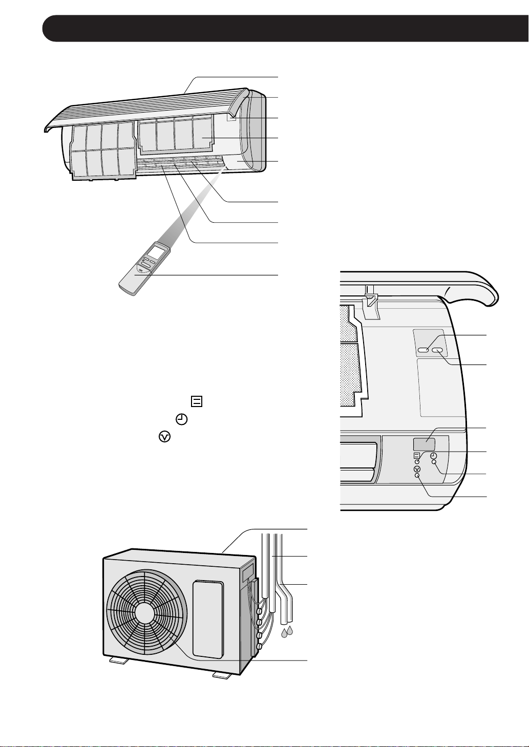
PART NAMES
TEST
RUN AUX.
INDOOR UNIT
To open the open panel, hold the bottom corners of the open panel and
gently pull the panel outwards.
0 TEST RUN Button
q AUX. Button
1
2
3
4
5
6
7
8
9
1 Inlet (Air)
2 Open Panel
3 Operation panel
4 Air Filters
5 Indicator Panel
6 Vertical Adjustment
Louvres
7 Horizontal Adjustment
Louvres
8 Outlet (Air)
9 Remote Control
0
q
w RECEIVER Window
e OPERATION Lamp (Red )
r TIMER Lamp (Yellow )
t BUSY Lamp (Red )
Blinks when the unit can not
operate due to the other unit
operating in different mode.
OUTDOOR UNIT
y
u
i
o
w
e
r
t
y Inlet (Air)
u Refrigerant Tube and
Interconnecting Cord
i Drainage Hose
o Outlet (Air)
NOTES:
1. Actual units may vary slightly from those shown above.
2. AE-M18AE-T is a multi-type outdoor unit and this unit is connected to two indoor units.
See the Installation Manual for detail installation instructions.
E-2
Page 5
PART NAMES
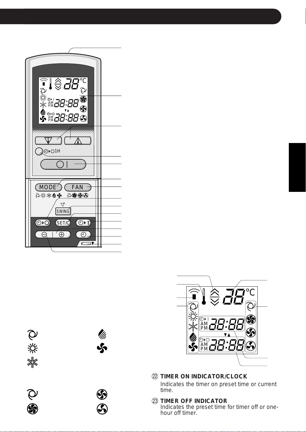
REMOTE CONTROL
C
AM
PM
AM
PM
1
2
3
1 TRANSMITTER
2 DISPLAY (Liquid Crystal Display)
3 THERMO. (Thermostat) Button
4 ONE-HOUR OFF TIMER Button
5 ON/OFF Button
6 MODE Button
7 FAN Button
8 TIMER OFF Button (for setting the timer)
1H
9 SWING Button
4
0 TIMER SET/CANCEL Button
q TIMER ON Button (for setting the timer)
w TIME ADVANCE Button
e CLOCK Button
MODE
FAN
5
6
7
8
9
SWING
SET/C
0
q
w
r Indicates BATTERY COMPARTMENT is
t TIME REVERSE Button
e
+-
r
t
L.C.D. REMOTE CONTROL DISPLAY
y THERMOSTAT SETTING FOR AUTO
AND DRY MODES
u TEMPERATURE SYMBOL
i TRANSMITTING SYMBOL
o MODE SYMBOLS
:AUTO :DRY
below this mark
y
u
i
o
AM
PM
ENGLISH
p
C
a
:HEAT :FAN ONLY
:COOL
p TEMPERATURE INDICATOR
a FAN SPEED SYMBOLS
:AUTO :LOW
:HIGH :SOFT
AM
PM
s TIMER ON INDICATOR/CLOCK
Indicates the timer on preset time or current
time.
d TIMER OFF INDICATOR
Indicates the preset time for timer off or onehour off timer.
E-3
s
d
Page 6
USING THE REMOTE CONTROL
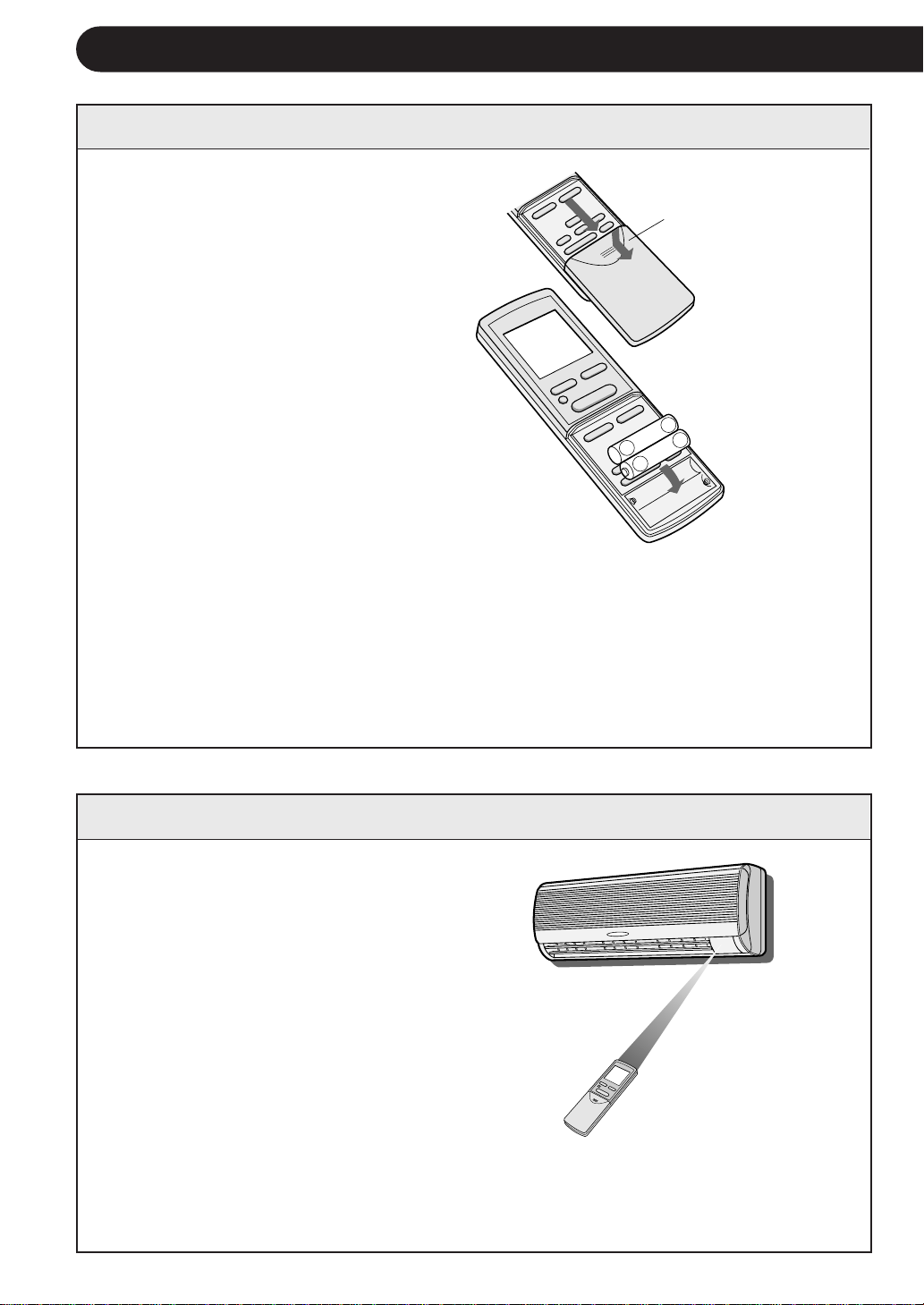
INSTALLING BATTERIES Use two size-AAA (R03) batteries.
1 Remove the remote control
cover.
Remote control
cover
2 Insert batteries in the compart-
ment, making sure the ± and
— polarities are correctly
aligned.
» The display indicates "AM
6:00" when batteries are properly installed.
+
-
3 Reinstall the cover.
NOTES:
» The battery life is approximately one year in normal use.
» When you replace the batteries, always change both batteries, and make sure
they are the same type.
» If the remote control does not operate properly after replacing the batteries, take
out the batteries and reinstall them again after 30 seconds.
» If you will not be using the unit for a long time, remove the batteries from the
remote control.
+
HOW TO USE THE REMOTE CONTROL
Point the remote control towards the
unit’s signal receiver window and
press the desired button. The unit
generates a beep when it receives the
signal.
» Make sure there is no curtain or other
object between the remote control and
the unit.
» The remote control can send signals
from up to 7 metres away.
NOTE:
If two indoor units are installed in the same room, both units may operate at the same
time by the remote control signal. The units should be installed apart from the other as
much as possible. Transmit the signal directly toward the unit you wish to operate.
E-4
Page 7

CAUTION
» Do not allow the signal receiver window to receive strong direct sunlight, since it can
adversely affect its operation. If the signal receiver window is exposed to direct sunlight,
close a curtain to block the light.
» Using a fluorescent lamp with a quick starter in the same room may interfere with
transmission of the signal.
» The unit can be affected by signals transmitted from the remote control of a television,
VCR or other equipment used in the same room.
» Do not leave the remote control in direct sunlight or near a heater. Also, protect the unit
and remote control from moisture and shock which can discolour or damage them.
SETTING THE CURRENT CLOCK TIME
ENGLISH
There are two clock modes: 12hour mode and 24-hour mode.
MODE
Å|
Å{
SWING
SET/C
FAN
+
-
Å{
Å|
3
1
2
Example: 5 o'clock in the afternoon
Clock Display
12-hour mode PM 5:00
24-hour mode 17:00
1 To set to the 12-hour mode, press the
CLOCK button once in the first step.
To set to the 24-hour mode, press the
CLOCK button twice in the first step.
2 Press the TIME ADVANCE or REVERSE
button to set the current time.
» Keep the button pressed to advance
or reverse the time display quickly.
3 Press the SET/C button.
» The colon (:) blinks to indicate that the
clock is functioning.
NOTE:
» The current time cannot be set when the
timer is operating.
E-5
Page 8

BASIC OPERATION
1
Press the MODE button to select the operation
mode.
AUTO HEAT COOL DRY FAN ONLY
AM
MODE
1H
SWING
SET/C
FAN
+-
Press the ON/OFF button to start operation.
2
» The red OPERATION lamp (
will light.
) on the unit
3
Press the THERMO. button to set the desired
3
2
5
4
1
temperature.
» In the AUTO and
DRY mode, the indicator bars represent
changes in temperature.
» In the COOL and HEAT mode, the tempera-
ture can be set within the range of 18 to 32
°C.
» In the FAN ONLY mode, the temperature
setting cannot be made.
Press the FAN button to set the desired fan
4
speed.
» In the DRY mode, the fan speed cannot be
changed.
» In the FAN ONLY mode, the fan speed can-
not be set to AUTO.
AUTO HIGH LOW SOFT
2°C higher
1°C higher
1°C lower
2°C lower
To turn off the unit, press the ON/OFF button
5
again.
» The red OPERATION lamp (
will turn off.
) on the unit
E-6
Page 9

NOTES:
This air conditioner is a multi-type, and two indoor units are connected to
one outdoor unit.
When the setting mode of one indoor unit differs from the other , the indoor
unit operated later may not work.
» When one indoor unit is operating in HEAT mode, the other unit can not operate
in COOL or DRY mode.
» When one indoor unit is operating in COOL or DRY mode, the other unit can not
operate in HEAT mode.
When the mode of the indoor unit later operated is different from
the one which is in operation, the red BUSY lamp
indoor unit later operated will blink.
( )
of the
How to reset the BUSY lamp
There are two ways to reset the blinking BUSY lamp
Change the remote control's mode and send the same mode signal which
the other indoor unit is operating in, or push the ON/OFF button of the
remote control.
( )
)
(
.
TIPS ABOUT AUTO MODE
In the AUTO mode, the temperature setting and mode are automatically
selected according to the room temperature when the unit is turned on.
Room temp. at operation start-up
Below 21°C HEAT 23°C
21°C-24°C DRY Room Temp. at start-up
24°C-26°C COOL 24°C
26°C-28°C COOL 25°C
Above 28°C COOL 26°C
Automatic Operation
Mode Thermostat Setting
ENGLISH
E-7
Page 10

ADJUSTING THE AIR FLOW DIRECTION
VERTICAL AIR FLOW
The air flow direction is automatically preset in each mode as follows for optimum
comfort:
COOL and DRY mode Horizontal air flow
FAN ONLY and HEAT mode
HOW TO ADJUST THE AIR FLOW DIRECTION
Diagonal air flow
Press the SWING button on the
remote control once.
» The vertical adjustment louvres
will change its angle continuously within the range shown
in the diagram.
Press the SWING button again
when the vertical adjustment louvres are at the desired position.
The louvres will stop moving
when the button is pressed.
HORIZONT AL AIR FLOW
Hold the horizontal adjustment
louvre levers as shown in the diagram and adjust the air flow direction. There are three louvre
levers.
Adjustment range
COOL and DRY mode
The adjustment range is
narrow in order to prevent condensation from
dripping.
FAN ONLY and HEAT mode
The range is wide so the
air flow can be directed
toward the floor.
Louvre levers
CAUTION
Never attempt to adjust the vertical adjustment louvres manually.
» Manual adjustment of the vertical adjustment louvres can cause the unit to malfunction
when the remote control is used for the adjustment.
» When the vertical adjustment louvres are positioned at the lowest position in the COOL or
DRY mode for an extended period of time, condensation may result.
E-8
Page 11

TIMER OPERATION
NOTE:
Before setting the timer, make sure the clock is properly set with the current time.
TIMER OFF
1 Press the TIMER OFF ( ) button.
2 The TIMER OFF indicator will blink; press the
TIME ADVANCE or REVERSE buttons to set
the desired time. (The time can be set in 10-
AM
minute increments.)
3 Point the remote control at the signal receiver
window on the unit and press the TIMER SET
(SET/C) button.
» The yellow TIMER lamp ( ) on the unit will
light.
» The unit will generate a beep when it re-
ceives the signal.
MODE
1H
SWING
SET/C
FAN
1
3
ENGLISH
+
-
TIPS ABOUT TIMER OFF OPERATION
2
When the TIMER OFF mode is set, the
temperature setting is automatically adjusted
to prevent the room from becoming
excessively hot or too cold while you sleep.
(Auto Sleep function)
COOL/DRY MODE:
» One hour after the time operation begins,
the temperature setting rises 1°C higher
than the original thermostat setting.
HEAT MODE:
» One hour after the timer operation begins,
the temperature setting drops 3°C lower
than the original thermostat setting.
NOTES:
»»
» The Auto Sleep function will not activate
»»
during the FAN ONLY mode.
»»
» The temperature setting cannot be ad-
»»
justed during the FAN ONLY mode.
TO CANCEL TIMER MODE
Press the TIMER CANCEL (SET/C) button.
» The yellow TIMER lamp (
) on the unit
will turn off.
» The current clock time will be displayed
on the remote control.
MODE
FAN
SWING
SET/C
+-
NOTE:
» If both TIMER ON and TIMER OFF are
set, the TIMER CANCEL button cancels
both settings.
TO CHANGE TIME SETTING
Cancel the TIMER seting first, then set it
again.
E-9
Page 12

TIMER OPERATION
TIMER ON
1 Press the TIMER ON ( ) button.
2 The TIMER ON indicator will blink. Press the TIME
AM
3 Point the remote control at the signal receiver
1H
MODE
FAN
4 Select the operation condition.
SWING
SET/C
3
1
ADVANCE or REVERSE button to set the desired
time. (The time can be set in 10-minute increments.)
window on the unit and press the TIMER SET
(SET/C) button.
» The yellow TIMER lamp (
light.
» The unit will generate a beep when it receives
the signal.
» The unit will turn on prior to the set time to allow
the room to reach the desired temperature by
the programmed time. (Awaking function)
) on the unit will
+-
COMBINED USE OF ON AND OFF TIMERS
You can use the ON and OFF timers in combination.
2
Example:
To stop operation at 11:00 p.m. and resume operation
(with the same mode and temperature settings) to bring
the room temperature to the desired level by 7:00 a.m.
1 Set the TIMER OFF to 11:00 p.m. during operation.
AM
PM
2 Set the TIMER ON to 7:00 a.m.
The arrow ( or ) between the TIMER ON indicator and
the TIMER OFF indicator shows which timer will activate
first.
NOTES:
» You cannot programme the TIMER ON and TIMER OFF to operate the unit at different
temperatures or other settings.
» Either timer can be programmed to activate prior the other.
E-10
Page 13

ONE-HOUR OFF TIMER
TEST
RUN
AUX.
When the ONE-HOUR OFF TIMER is set, the unit will stop operating after one hour.
1 Press the ONE-HOUR OFF TIMER button.
» The remote control displays “1 H”.
» The unit will stop operating after one hour.
2 To turn off the unit within an hour before the
ONE-HOUR OFF TIMER activates, press the
ON/OFF button.
1H
1
2
» The OPERATION lamp (
turn off.
If you wish to operate the unit for another
hour before the ONE-HOUR OFF TIMER
activiates, press the ONE-HOUR OFF TIMER
button again during operation.
NOTE:
» The ONE-HOUR OFF TIMER operation has pri-
ority over TIMER ON and TIMER OFF operations.
) on the unit will
ENGLISH
AUXILIARY MODE
Use this mode when the remote control is not available.
TO TURN ON
Lift the front panel of the indoor unit and press the AUX.
button on the operation panel.
» The red OPERATION lamp (
and the unit will start operating in the AUTO mode.
» The fan speed and temperature setting are set to
AUTO.
TO TURN OFF
Press the AUX. button on the operation panel again.
» The red OPERATION lamp (
off.
NOTE:
» If the AUX. button is pressed during normal opera-
tion, the unit will turn off.
) on the unit will light
) on the unit will turn
E-11
Page 14

TEST RUN MODE
Use the test run mode only for a test operation. Do not use the test run mode for other
than operation testing since the thermostat control is inactive in this mode and the unit
remains in continuous operation.
Make sure the unit is turned off before conducting a test run.
TO TURN ON
Lift the front panel of the indoor unit and press the
TEST RUN button on the operation panel.
» The red OPERATION lamp (
blink and the unit will start operating in the COOL
mode.
» The temperature setting is not set. (the compressor
runs continuously.)
TO TURN OFF
Press the AUX. button on the operation panel.
» The red OPERATION lamp (
turn off.
) on the unit will
) on the unit will
TEST
RUN
AUX.
NOTE:
» To conduct a heat mode test run, press the MODE
button on the remote control to set the unit in the
HEAT mode.
E-12
Page 15

ADDITIONAL NOTES ON OPERATION
OPERATING TEMPERATURE RANGE
INDOOR TEMP. OUTDOOR TEMP.
COOLING
upper limit
lower limit
upper limit
HEATING
lower limit
D.B. = Dry-bulb W.B. = Wet-bulb
32˚C D.B. 43˚C D.B.
23˚C W.B. -
21˚C D.B. 21˚C D.B.
15˚C W.B. -
27˚C D.B. 24˚C D.B.
- 18˚C W.B.
20˚C D.B. -8.5˚C D.B.
- -9.5˚C W.B.
WHEN A POWER FAILURE OCCURS
This air conditioner has a memory function to store settings when a power failure occurs.
After power recovery, the unit will automatically re-start in the same settings which were active before
the power failure, except for timer settings.
If the timers were set before a power failure, they will need to be re-set after power recovery.
PREHEATING FUNCTION
In the HEAT operation, the indoor fan may not start for two to five minutes after the unit is turned on
to prevent cold air from blowing out of the unit.
DE-ICING FUNCTION
» When ice forms on the heat exchanger in the outdoor unit during the HEAT operation, the
automatic de-icer provides heat for about 5 to 10 minutes to remove the ice. During de-icing, the
inside and outside fans stop operating.
» After de-icing is completed, the unit automatically resumes operation in the HEAT mode.
» The built-in protective
device may prevent the
unit from operating when
used out of this range.
» Condensation may form
on the air outlet if the
unit operates continuously in the COOL or
DRY mode when humidity is over 80 percent.
ENGLISH
HEATING EFFICIENCY
» The unit uses a heat pump to obtain heat from the outside air and releases it into the room. The
outside air temperature therefore greatly affects the heating efficiency.
» If the heating efficiency is reduced due to low outside temperatures, use an additional heater.
» It takes time to warm up and heat the entire room because of the forced air circulation system.
TIPS ON SAVING ENERGY
Below are some simple ways to save energy when you use your air conditioner.
SET THE CORRECT TEMPERATURE
» Setting the thermostat 1°C higher than the desired temperature in the COOL mode and 2°C lower
in the HEAT mode will save approximately 10 percent in power consumption.
» Setting the temperature lower than necessary during cooling operation will result in increased
power consumption.
BLOCK DIRECT SUNLIGHT AND PREVENT DRAFTS
» Blocking direct sunlight during cooling operation will reduce power consumption.
» Close the windows and doors during cooling opeation and heating operation.
SET PROPER AIR FLOW DIRECTION TO OBTAIN THE BEST AIR
CIRCULATION
KEEP FILTERS CLEAN TO ENSURE THE MOST EFFICIENT OPERATION
MAKE MOST OF THE TIMER OFF FUNCTION
DISCONNECT THE POWER CORD WHEN THE UNIT IS NOT USED FOR AN
EXTENDED PERIOD OF TIME
» The indoor unit still consumes a small amount of power when it is not operating.
E-13
Page 16

MAINTENANCE
Be sure to disconnect the power cord from the wall outlet or turn off the circuit
breaker before performing any maintenance.
CLEANING THE FILTERS
1 TURN OFF THE UNIT
2 REMOVE THE FILTERS
1
2
3
3 CLEAN THE FILTERS
3
2
1
4 REINSTALL THE FILTERS
The air filters should be cleaned every two weeks.
1 Open the front panel.
2 Push the air filters up slightly to unlock them.
3 Pull the air filters down to remove them.
Use a vacuum cleaner to remove dust. If the
filters are dirty, wash them with warm water
and a mild detergent. Dry filters in the shade
before reinstalling.
1 Reinstall the filters in the original positions.
2 Close the front panel.
3 Push the centre part of the panel firmly to
lock it in place.
CLEANING THE UNIT AND THE REMOTE CONTROL
» Wipe them with a soft cloth.
» Do not directly splash or pour water on them. Water can cause electrical shock or
equipment damage.
» Do not use hot water, thinner, abrasive powders or strong solvents.
MAINTENANCE AFTER AIR
CONDITIONER SEASON
1 Operate the unit in the FAN
ONLY mode for about half a day
to allow the mechanism to thoroughly dry.
2 Stop the operation and unplug
the unit. Turn off the circuit
breaker, if you have one exclusively for the air conditioner.
MAINTENANCE BEFORE
AIR CONDITIONER SEASON
1 Make sure that the air filters are
not dirty.
2 Make sure that nothing obstructs
the air inlet or outlet.
3 Check the outdoor mounting rack
periodically for wear and to make
sure it is firmly in place.
3 Clean the filters, then reinstall
them.
E-14
Page 17

BEFORE CALLING FOR SERVICE
The following conditions do not denote equipment malfunctions
UNIT DOES NOT OPERATE
The unit will not operate if it is
turned on immediately after it is
turned off. The unit will not operate
immediately after the mode is
changed. This is to protect the
internal mechanisms. Wait 3
minutes before operating the unit.
UNIT DOES NOT SEND OUT
WARM AIR
The unit is preheating or de-icing.
ODORS
Carpet and furniture odors that entered into the unit and the air conditioner's inner component odors at
the early stage of installation may
be sent out from the unit.
CRACKING NOISE
The unit may produce a cracking
noise. This sound is generated by
the friction of the front panel and
other components expanding or
connecting due to a temperature
change.
SWISHING NOISE
The soft, swishing noise is the sound of the
refrigerant flowing inside the unit.
WATER VAPOUR
» In the COOL and DRY operation, water
vapour can sometimes be seen at the air
outlet due to the difference between the
room air temperature and the air discharged by the unit.
» In the HEAT operation, water vapour may
flow out of the outdoor unit during deicing.
UNIT DOES NOT OPERATE IN YOUR
REQUESTED MODE
» When one indoor unit is operating in
COOL mode, you can not operate the
other unit in HEAT mode. (OPERATION
lamp (
(
will not start.)
» When one indoor unit is operating in
HEAT mode, you can not operate the
other unit in COOL nor DRY mode. (OPERATION lamp (
BUSY lamp (
fan will rotate.)
) will light up, but BUSY lamp
) will blink and HEAT mode operation
) will light up, but
) will blink and only the
ENGLISH
If the unit appears to be malfunctioning, check the following points before calling for
service.
IF THE UNIT FAILS TO OPERATE
Check to see if the circuit breaker has tripped or the fuse has blown.
IF THE UNIT FAILS TO COOL OR HEAT THE ROOM EFFECTIVELY
Check the filters. If dirty,
clean them.
Make sure windows and
doors are closed tightly.
Check the outdoor unit to
make sure nothing is
blocking the air inlet or
outlet.
A large number of people
in the room can prevent
the unit from achieving the
desired temeperature.
Check the thermostat is
for proper setting.
Check whether any
heat-generating appliances are operating in
the room.
E-15
Page 18

BEFORE CALLING FOR SERVICE
IF THE UNIT FAILS TO RECEIVE THE REMOTE CONTROL SIGNAL
Check whether the remote control batteries
have become old and
weak.
Try to send the signal again
with the remote control
pointed properly towards
the unit’s signal receiver
window.
Check whether the remote control batteries
are installed with the
polarities properly
aligned.
OPTION KIT
Air Purifying Filter Unit
Use of the air purifying filter unit will help remove dust from the air during operation.
Contact your dealer for the purchase of this option. Replacement air purifying filters are also
available.
Air Purifying Filter Unit
Replacement Filters
Type AZ-F954
Type AZ-F904
E-16
Page 19

ENGLISH
Page 20

Printed in Thailand
SHARP CORPORATION
OSAKA, JAPAN
TINSEA251JBRZ TL 0EO 1
 Loading...