

Page 1

q
L
PROGRAMMING MANUA
ER-A520
ER-A530
ELECTRONIC
CASH REGISTER
MODEL
CONTENTS
CODE : 00Z
ER-A520
ER-A530
(For “U/A” version)
ERA520UPME
CHAPTER 1. SERVICE (SRV) MODE . . . . . . . . . . . . . . . . . . . . . .1 - 1
CHAPTER 2. READING OF THE SRV MODE PROGRAM . . . . . .2 - 1
CHAPTER 3. SERVICE MODE PROGRAMMING. . . . . . . . . . . . .3 - 1
CHAPTER 4. OP X/Z, X1/Z1, X2/Z2 MODE. . . . . . . . . . . . . . . . . .4 - 1
*
For settings related to the USER PROGRAMMING (PGM1, PGM2) mode,
please refer to the applicable Instruction Manual provided for the ER-A520
and ER-A530 model cash registers.
Parts mark ed w ith "!" are important for maintaining the safety of the set. Be sure to replace these parts with specified
ones for maintaining the safety and performance of the set.
This document has been pub lished to be used
SHARP CORPORATION
for after sales service only.
The contents are subject to change without notice.
Page 2

CHAPTER 1. SERVICE (SRV) MODE
A SRV-key is required to perform the 2 types of RESET procedures :
MASTER RESET :
PROGRAM RESET :
There are 2 classifications of MASTER RESET operations.
MASTER RESET 1: Normal MASTER RESET
MASTER RESET 2: Enables the layout of the fixed keys in addition
Clears the entire memory and resumes initial values.
Initializes the program without clearing memory.
Clears the entire memory and resumes initial values.
to performing a MASTER RESET 1.
Fixed keys: [0] [1] [2] [3] [4] [5] [6] [7] [8] [9] [00]
[000] [.] [CL] [@/FOR] [SBTL]
[CA/AT]
1. RESET PROC EDURES
■MASTER RESET 1
Please select “Procedure A” or “Procedure B” as required.
Procedure A: 1) Set the mode switch to the (SRV’) position.
2) Plug the AC power cord into the wall outlet.
3) While holding down the JOURNAL FEED key, turn the
mode switch to (SRV) position from the (SRV’) posit ion.
Procedure B: 1) Unplug the AC power cord from the wall outlet.
2) Set the mode switch to the (SRV) position.
3) While holding down the JOURNAL FEED key, plug in
the AC cord to the wall outlet.
Note: Procedure B cannot reset the hardware.
Procedure A must be used to reset the hardware.
■MASTER RESET 2
Please select “Procedure A” or “Procedure B” as required.
Procedure A: 1) Set the mode switch to the (SRV’) position.
2) Plug in the AC power cord into the wall outlet.
3) While holding down the JOURNAL FEED key & the
RECEIPT FEED key, turn the mode switch to (SR V)
position from the (SRV’) position.
4) Program the [0] [1] [2] [3] [4] [5] [6] [7] [8] [9] [00] [000]
[.] [CL] [@/FOR] [SBTL] [CA/AT] keys by depressing
the desired keyboard locations in this order.
Note: If the [000] key is not required, depress the location
where the [.] key (next step) will be located, and
the [000] key will be inhibited.
■PROGRAM RESET
Please use “Procedure A”, “Procedure B” or “Procedure C”
Prodecure A: 1) Set the mode switch to the (SRV’) position.
2) Plug in the AC power cord into the wall outlet.
3) Without pressing any function keys, turn the mode
switch to the (SRV) position from the (SRV’) position.
Procedure B: 1) Unplug the AC power cord from the wall outlet.
2) Set the mode switch to the (SRV) position.
3) Without pressing any function keys, plug the AC power
cord into the wall outlet.
Procedure C: 1) Unplug the AC power cord from the wall outlet.
2) Set the mode switch to the PGM2 position.
3) While depressing the JOURNAL FEED key & the
RECEIPT FEED key, plug in the AC power cord to the
wall outlet.
*
“Procedure C” can be executed when SRV#926-B: PROGRAM
RESET in PGM2 = 4 (enabled).
Note: Reset messages are printed on the journal-side of the printer.
2. DISPLAY AND PRINT
■MASTER RESET 1
1) During the memory clearing and initializing, “
displayed on upper line.
2) When the MASTE R RE SET is p erfor med, the buzz er beep s 3 tim es
and the MASTER RESET
***
message is printed on the journal.
***
■MASTER RESET 2
1) The function key code and text that may be programmed is
displayed.
ex) 001 0 KEY
2) After placement of the fixed function keys, “
played on upper line during memory clearing and initializing.
3)
When the MASTER RESET is fully executed, the buzzer beeps 3
times and the MASTER RESET
nal.
3
002 1 KEY
***
message is printed on the jour-
***
3
MRS.
■PRGRAM RESET
1)
When a PROGRAM RESET is performed, R “PROGRAM RESET
is printed (the buzzer does not beep).
...
MRS.
***
***
” is dis-
***
” is
”
Procedure B: 1) Unplug the AC power cord from the wall outlet.
2) Set the mode switch to the (SRV) position.
3) While holding down the JOURNAL FEED key & the
RECEIPT FEED key, plug the AC power cord into the
wall outlet.
4) Repeat the same sequence outlined in “Procedure A”
Note: Procedure B cannot reset the hardware.
Procedure A must be used to reset the hardware.
ER-A520U/A530U SERVICE (SRV) MODE
1 – 1
Page 3

CHAPTER 2. Reading of the SRV mode program
List of program reports
JOB# Report name
900 SRV-mode program (System presets)
950 Keyboard layout report (Function keys only).
951 Keyboard layout report (Direct Dept. key & PLU key only)
970 File allocation report
990 SSR report
Note: Program reports are printed on the RECEIPT & JOURNAL.
This following sample program readings are based on the ER-A520.
*
[JOB# 900]
Reading the contents of the SRV mode programming
Key operation
900 CA/AT@/FOR
[JOB# 950]
Reading the contents of the SRV mode programming for the FREE KEY
LAYOUT setting. (Function Keys)
Key operation
950 CA/AT@/FOR
<SAMPLE>
Date/Machine No.
CC-No. / Time / Server name
/ Server code
<SAMPLE>
Date/Machine No.
CC-No. / Time / Server name
Job code
Contents of system preset
General Z1 reset counter
Houlry Z1 reset counter
PLU Z1 reset counter
Cashier Z1 reset counter
GLU/PBLU Z1 reset counter
General Z2 reset counter
Daily net Z2 reset counter
GT2
GT3
Training GT
PGM2 mode secret code
Training Server No.
Training mode title
Euro symbol programming for
TM-295
Domestic currency symbol
Initial text mode
gramming
pro
/ Server code
Job code
Key No. / Key text / Location No.
[JOB# 951]
Reading the contents of the SRV mode programming for FREE KEY
LAYOUT setting. (Dept. & PLU keys)
Key operation
951 CA/AT@/FOR
<SAMPLE>
Date/Machine No.
CC-No. / Time / Server name
Job code
Key No. / Key label / Location No.
/ Server code
The program readings are printed in the text mode formats previously
selected.
The contents of the programming are printed only on the journal in
*
individual formats shown above.(No header is printed.)
ER-A520U/A53 0U Reading of the SR V mode program
2 – 1
Page 4
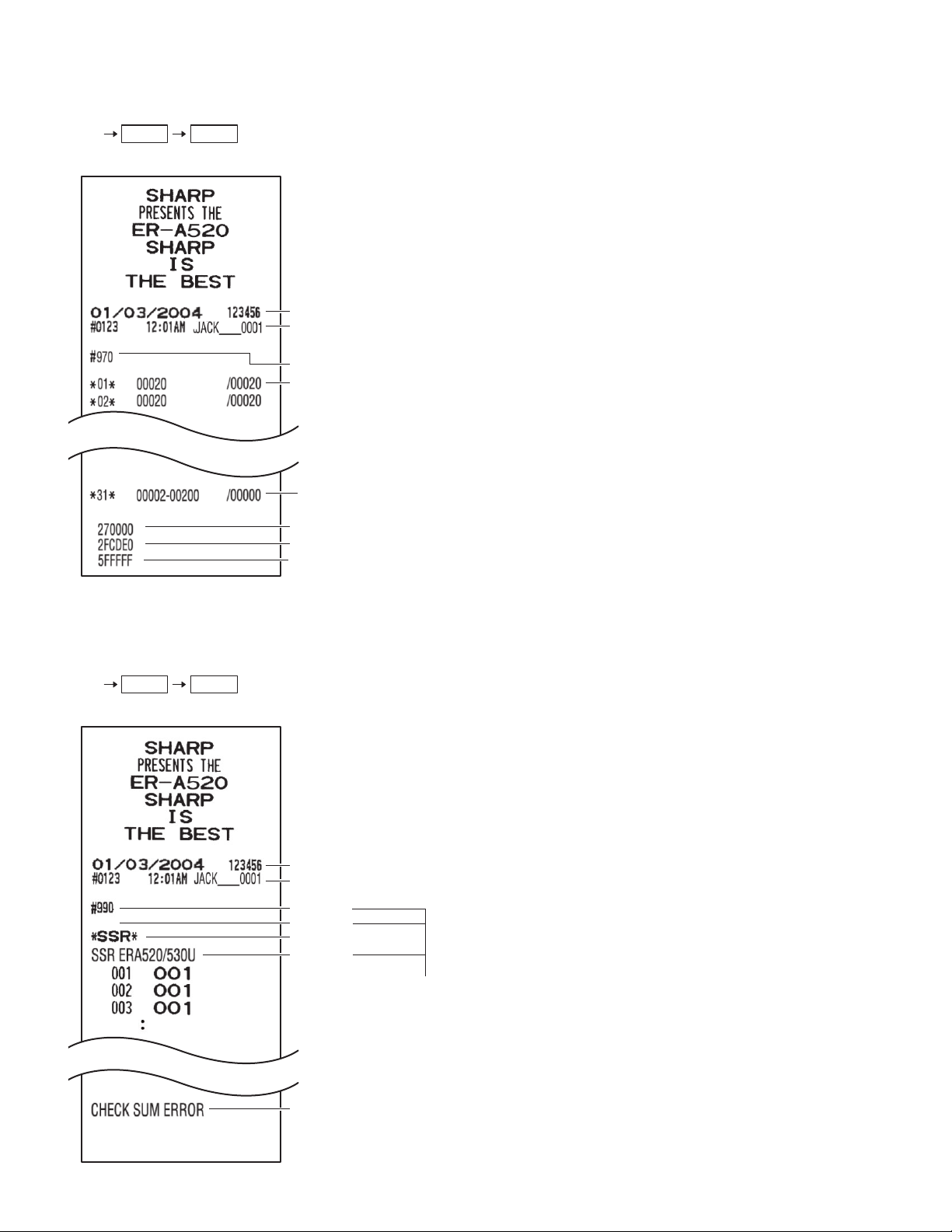
[JOB#970]
Reading of file allocation
Key operration.
970 CA/AT@/FOR
<SAMPLE>
Date/Machine No.
CC-No. / Time / Server name
Job code
File group No. / No. of records
File group No. / No. of index
records / No. of data records
File memory start address
Free memory start address
Memory end address
/ Server code
/ No. of used records
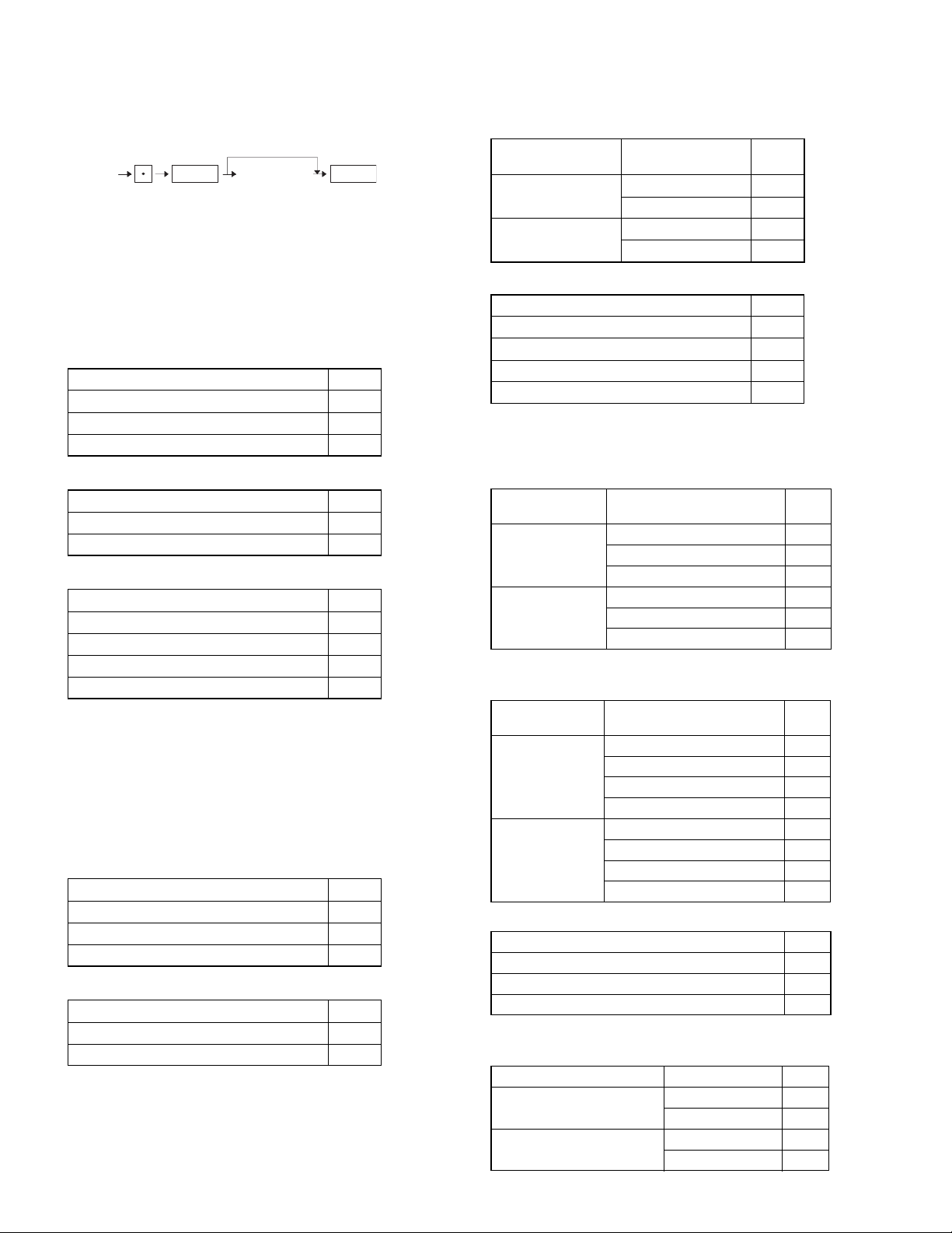
[JOB#990]
Reading the contents of the SRV mode programming for the SSR
settings.
Key operation
990 CA/AT@/FOR
<SAMPLE>
Date/Machine No.
CC-No. / Time / Server name
Job code
Space line
(Fixed message)
SSR No.
/ Server code
(Reading report only)
(Fixed message)
ER-A520U/A53 0U Reading of the SR V mode program
2 – 2
Page 5
CHAPTER 3. Service mode programming
The following key operations required for programming system presets.
0
XXX
(Job#)
Note: the ★ mark indicates the MRS default setting.
@/FOR
[A] [B] [C] [D]
Numeric entry
digits max
4
CA/AT
[JOB#901] ER-A520: MRS = 0002
ER-A530: MRS = 0002
#901-A: Not used (Fixed at “0”)
#901-B: Tax system
1. TAX system 901-B
Auto TAX 1~4 Manual TAX 0 ★
Canadian TAX (Type1 to Type10) 6
Canadian TAX (TypeΙΙ: VAT on VAT) 7
#901-C: 1. Rounding system
1. Rounding system 901-C
Normal 0 ★
Singapore 8
#901-D: 1. TAB setting
1. TAB setting 901-D
0. 0
0.0 1
0.00 2 ★
0.000 3
[JOB#902] ER-A520: MRS = 0000
ER-A530: MRS = 0000
#902-A, B, C, D: Not used (Fixed at “0000”)
[JOB#903] ER-A520: MRS = 5000
ER-A530: MRS = 5000
#903-A: 1. Baud Rate for ECR data copying
1. Baud rate (bps) 903-A
9600 4
19200 5 ★
38400 6
#903-B: 1. Symbol of scale entry
1. Symbol of scale entry 903-B
“LB” 0 ★
“KG” 2
#903-C: 1. Entry of tare
2. Unit of weight for the scale
1. Entry of tare 2. Unit of weight for
Disallowed
Allowed
#903-D: 1. Food stamp system
1. Food stamp system 903-D
No food stamps 0 ★
TAX not payable in food stamps 1
TAX payable in food stamps 2
Food stamp forgiveness 3
the scale
2ID (3ID) + 2DD 0 ★
1ID (2ID) + 3DD 1
2ID (3ID) + 2DD 2
1ID (2ID) + 3DD 3
903-C
[JOB#904] ER-A520: MRS = 0000
ER-A530: MRS = 0000
#904-A: 1. Printing of date
2. Fraction treatment at gasoline (OIL) q’ty calculation
1. Printing of date
Yes
No
#904-B: 1. Printing of the consecutive No.
2. Decimal point position of gasoline (OIL) q’ty
1. Printing of the
consecutive No.
Yes
No
#904-C: 1. Fraction treatment at gasoline discount
1. Fraction treatment at gasoline discount
0. Rounding 0 ★
1. Raising to unit 1
2. Disregarding 2
#904-D: 1. TAB for the gasoline unit price
2. Gasoline function
1. TAB for the gasoline unit price
0.000
2.Fraction treatment at gasoline (OIL) q’fy calculation
0. Rounding 0 ★
1. Raising to unit 1
2. Disregarding 2
0. Rounding 4
1. Raising to unit 5
2. Disregarding 6
2.Decimal point position of
gasoline (OIL) q’fy
2.Gasoline function 904-D
0.00
00★
0.0 1
0.00 2
0.000 3
04
0.0 5
0.00 6
0.000 7
Disable 0 ★
Enable 1
Disable 2
Enable 3
904-A
904-B
904-C
ER-A520U/A530U Service mode programming
3 – 1
Page 6

[JOB#905] ER-A520: MRS = 0005
ER-A530: MRS = 0005
#905-A: 1. Taxable 4 subtotal printing on X/Z report.
2. Gross Tax 4 and refund Tax 4 total print on X/Z report.
3. Net Tax 4 total print on X/Z report.
1. Taxable 4
SBTL
Print
Skip
#905-B: 1. Tax printing when taxable subtotal is zero.
2. Tax printing when GST is VAT.
3. Tax printing when tax is zero.
1. Taxable
subtotal is
zero
Skip
Print
#905-C: 1. GST EXPT print on X/Z report
#905-D: 1. TAX METHOD
Tax4
method
(GST)
1
Type
Type
Type
Type
Type
Type
Type
Type
Type
Type
VAT VAT
2
3
VAT
4
5
Add on Tax
6
7
Add on Tax VAT
8
9
Add on Tax
F
2. Gross Tax 4
and refund
Tax 4
Print
Skip
Print
Skip
2. GST is VAT 3. Tax is zero
Print
Skip
Print
Skip
1. GST EXPT 905-C
Print 0 ★
Skip 4
Tax3 method Tax2, 1
GST PST
Add
on Tax
3. Net Tax 4
Print 0 ★
Skip 1
Print 2
Skip 3
Print 4
Skip 5
Print 6
Skip 7
Print 0 ★
Skip 1
Print 2
Skip 3
Print 4
Skip 5
Print 6
Skip 7
method
(PST)
Tax on Tax 0
Tax on Base 1
Tax on Tax 2
Tax on Base 3
Tax on Tax 4
Tax on Base 5 ★
Tax on Tax 6
Tax on Base 7
Tax on Tax 8
Tax on Base 9
905-A
905-B
905-D
[JOB#906] ER-A520: MRS = 0021
ER-A530: MRS = 0021
#906-A: 1. Printing of Dept. and PLU/UPC (EAN) codes
2. E
ntry which makes the PLU/UPC (EAN) stock counter negative
1. Printing of Dept. and
PLU/UPC (EAN) codes
NO
YES
#906-B: 1. Bottle return function
2. Hash setting
1. Bottle return function 2. Hash setting 906-B
Disable
Enable
#906-C: 1. Split pricing counting
2. Multiplication entry
1. Split pricing counting 2. Multiplication entry 906-C
Quantity
Package
#906-D: 1. UPC/PLU price look up at refund entry
2. Presetting of consecutive No.
3. Fractional quantity
1. UPC/PLU price
look up at refund
entry
Yes
No
2. Entry which makes the
PLU/UPC (EAN) stock
counter negative
Allowed unconditionally 0 ★
Operation allowed despite
error message
Inhibit entry 2
Allowed unconditionally 4
Operation allowed despite
error massage
Inhibit entry 6
Disable 0 ★
Enable 2
Disable 4
Enable 6
Multiplication 0
Successive multiplication 1
Split pricing 2 ★
Multiplication 4
Successive multiplication 5
Split pricing 6
2. Presetting of
consecutive No.
Yes
No
Yes
No
3. Fractional
quantity 906-D
No 0
Yes (3 digit
decimal place)
No 2
Yes (3 digit
decimal place)
No 4
Yes (3 digit
decimal place)
No 6
Yes (3 digit
decimal place)
906-A
1
5
1 ★
3
5
7
ER-A520U/A530U Service mode programming
3 – 2
Page 7
[JOB#907] ER-A520: MRS = 0010
ER-A530: MRS = 0010
#907-A: Not used (Fixed at “0”)
#907-B: 1. UPC (EAN) code printing on journal
2. UPC (EAN) code printing on receipt
1. UPC (EAN) code printing on journal
Yes
No
#907-C: 1. In case of individual and all Server CCD, X report before
CCD entry
2. UPC (EAN) code
printing on receipt
Yes 0 ★
No 1
Yes 2
No 3
907-B
#908-C: 1. Void mode adds to the Hourly Report totals
2. X1/Z1 report at X2/Z2 mode
3. Resetting of consecutive number in Z1
1. Void mode
adds to Hourly
Report totals
No
Yes
2. X1/Z1 report
at X2/Z2
mode
Enable
Disable
Enable
Disable
3. Resetting of
consecutive
No.in Z1
No 0 ★
Yes 1
No 2
Yes 3
No 4
Yes 5
No 6
Yes 7
908-C
2. MINUS department (PLU/UPC (EAN))
1.
In case of individual and
all Server CCD, X Report
before CCD entry
Enable
Disable
#907-D: 1. CCD COMPULSION
1. CCD COMPULSION 907-D
FOR ALL SERVER 0 ★
FOR INDIVIDUAL SERVERS 1
NON-COMPULSORY 2
2. MINUS department
(PLU/UPC (EAN)) 907-C
Disable 0
Enable 1 ★
Disable 2
Enable 3
[JOB#908] ER-A520: MRS = 0000
ER-A530: MRS = 0000
#908-A: Printing of GT totals on the General Z report
GT1 (NET) GT2 (+) GT3 (-) 908-A
Print
Print
Skip
Print
Skip
Skip
#908-B: Printing of GT totals on the General X report
GT1 (NET) GT2 (+) GT3 (-) 908-B
Skip
Skip
Print
Skip
Print
Print
Print 0 ★
Skip 1
Print 2
Skip 3
Print 4
Skip 5
Print 6
Skip 7
Skip 0 ★
Print 1
Skip 2
Print 3
Skip 4
Print 5
Skip 6
Print 7
#908-D: 1. Printing X/Z report (Except the individual cashier)
2. GT resetting at Z1 General Report resetting
1. Printing X/Z report 2. GT resetting at Z1 908-D
Receipt & Journal
Journal
No 0 ★
Yes 1
No 4
Yes 5
[JOB#909] ER-A520: MRS = 2000
ER-A530: MRS = 2000
#909-A: 1. Printing of Training GT on the X report
2. Printing of Training GT on the Z report
1. Printing of Training GT
on the X report
NO
YES
#909-B: 1. Printing of data on PLU resetting report
1. Printing of data on PLU resetting report 909-B
#909-C: 1. Printing of Void mode & MGR Void in the General Z2 report
2. Printing of Void mode & MGR Void in the General Z1 report
1. Printing of Void mode
& MGR Void in the
General Z2 report
YES
NO
#909-D: Not used (Fixed at “0”)
2. Printing of Training GT
on the Z report
YES 0
NO 1
YES 2 ★
NO 3
Yes 0 ★
No 4
2. Printing of Void mode
& MGR Void in the
General Z1 repor
YES
NO 2
YES 4
NO 6
909-A
909-C
0
★
ER-A520U/A530U Service mode programming
3 – 3
Page 8

[JOB#910] ER-A520: MRS = 0204
ER-A530: MRS = 0204
#910-A: 1. Overlapped server/cashier function
1. Overlapped server/cashier function 910-A
No 0 ★
Yes 1
When the overlap server/cashier is used, the overlapped server file must be created.
#910-B: 1. Server/Cashier code display
2. Auto server/cashier sign off at the end of transaction
1. Code display
Hidden
Appear
#910-C: Not used (Fixed at “0”)
#910-D: 1. Server/Cashier system code entry (Fixed at “4”)
2. Auto sign off at the end of
transaction
No
(After server/cashier Z1 only)
Yes (Everytime) 1
No
(After server/cashier Z1 only)
Yes (Everytime) 3
910-B
0
2
★
[JOB#911] ER-A520: MRS = 0000
ER-A530: MRS = 0000
#911-A: 1. Fraction treatment
1. Fraction treatment 911-A
Round off 0 ★
Round up unit 1
Disregarding 2
#911-B: 1. C/D check of UPC (EAN)
2. C/D check when a manual PB/CB entry is made
1. C/D check of
UPC (EAN)
No
Yes
#911-C: Not used (Fixed at "0")
#911-D: 1. RECEIPT/SLIP header format
1. RECEIPT/SLIP header format 911-D
Format1 : Normal sized Consec.#, Server Name and code
Format2 : Double-sized Consec.#, normal sized Server
Name and code
Format3 : Double sized Consec.# and Server code
(Server Name not printed)
2. C/D check when a
a manual PB/CB
entry is made
No 0 ★
Yes 1
No 4
Yes 5
911-B
0
2
4
★
[JOB#912] ER-A520: MRS = 0061
ER-A530: MRS = 0060
#912-A: 1. Date print format
Date format 912-A
Month/Day/Year 0 ★
Day/Month/Year 1
Year/Month/Day 2
#912-B: 1. Time system
1. Time system 912-B
12H 0 ★
24H 1
#912-C: 1. Receipt After format
2. Copy receipt function
3. Footer print control
1. Receipt After 2. Copy receipt
No
Totals only
Yes
No
Detail
Yes
#912-D: 1. Receipt LOGO Message control.
1. Receipt LOGO Message control 912-D
3-line header instead of a LOGO
Graphical LOGO only
Graphical LOGO and 3-line footer 2
6-line header 3
Graphical LOGO and 3-line header 4
3-line header and 3-line footer 5
Type : 0
Header
3. Footer print
control
All receipt 0
On selected func-
tion keys at the
time of finalization
All receipt 2
On selected func-
tion keys at the
time of finalization
All receipt 4
On selected func-
tion keys at the
time of finalization
All receipt 6 ★
On selected func-
tion keys at the
time of finalization
1
LOGO
LOGO
912-C
0
1
1
3
5
7
★
(ER-A530)
★
(ER-A520)
32
Footer
ER-A520U/A530U Service mode programming
3 – 4
4
LOGO
5
Page 9

[JOB#913] ER-A520: MRS = 0104
ER-A530: MRS = 0104
#913-A: 1. Validation Total amount contents
1. Validation Total amount contents 913-A
Total amount 0 ★
Tendered amount 1
#913-B: 1. Prin ti ng of s ubt o ta l a mo un t w h en S U BTO TA L k ey is depr essed
2. Printing of MDSE ST
3. Escape the compulsion of Validation and SLIP print
1. Printing of
subtotal by ST
key
No
Yes
#913-C: 1. Buzzer duration is approx. 2 sec. after lock error
2. Buffered keyboard
1. Buzzer duration after
lock error
2-sec. duration
Constant
(until CL key depression)
#913-D: 1. Compulsion of Drawer closing prior to sales entries
2. Error system
3. Key touch sound
1. Drawer
closing
Non-compulsory
Compulsory
2. Printing of
MDSE ST
No
Yes
No
Yes
2. Buffered keyboard 913-C
2. Error system
All lock error Enable 0
Misoperation
(One shot error)
All lock error Enable 4 ★
Misoperation
(One shot error)
3. Escape the
compulsion of
Validation and
SLIP print
Disable 0
Enable 1 ★
Disable 2
Enable 3
Disable 4
Enable 5
Disable 6
Enable 7
Yes 0 ★
No 1
Yes 2
No 3
3. Key touch
sound
Disable 1
Enable 2
Disable 3
Disable 5
Enable 6
Disable 7
913-B
913-D
[JOB#914] ER-A520: MRS = 3100
ER-A530: MRS = 1100
#914-A: 1. Receipt issuing at no-sale
2. [NS] key is separate from [CA/AT] key for the no-sale function
3. Tax delete operation
1. Receipt
issuing at
no-sale
Enable
Disable
#914-B: 1. No-sale after NON ADD code entry
#914-C: 1. Void mode operations
#914-D: 1.Manual tax entries
2. [NS] key is separate separation
from [CA/AT ] k e y
for no-sale function
Yes
No
Yes
No
1. No-sale after # entry 914-B
Disable 0
Enable 1
2. Non-add code entry at the beginning of a sales transaction
1. Void mode
operations
Enable
Disable
2. Check cashing function
3. Non-add No. entry
1. Manual tax
entries
Enable
Disable
2. Check cashing function
Disable
Disable
3. Tax delete
operation
Inhibit 0
Enable
Inhibit
Enable
Inhibit 4
Enable 5
Inhibit 6
Enable 7
2.Non-add code entry
at the beginning of a
sales transaction
Non-compulsory 0 ★
Compulsory 1
Non-compulsory 2
Compulsory 3
3. Non-add
Enable
Enable
914-A
★
1
(ER-A530)
2
★
3
(ER-A520)
914-C
No. entry
Enable 0 ★
Disable 1
Enable 2
Disable 3
Enable 4
Disable 5
Enable 6
Disable 7
914-D
★
[JOB#915] ER-A520: MRS = 0000
#915-A, B: Not used (Fixed at “00”)
#915-C: 1. ST (-), ST (%) as many times needed/once only
1. ST (-), ST (%) as many times needed/once only
#915-D: Not used (Fixed at “0”)
ER-A520U/A530U Service mode programming
3 – 5
ER-A530: MRS = 0000
915-C
Unlimited 0 ★
Once only 2
Page 10

[JOB#916] ER-A520: MRS = 1400
ER-A530: MRS = 1400
#916-A: 1. Print format when text and amount overlaps each other in
REG mode
1. Print format when text and amount overlaps each other in REG mode
Truncate 0
2 line print 1 ★
#916-B: 1. Finalization by Charge when the SUBTOTAL is 0 or below
2. Food stamp subtotal entry before food stamp tender
1. Finalization by Charge
when ST is 0 or below
RFND type of sales only
Always
#916-C: 1. Negative merchandise subtotal
2. Subtotal entry compulsory before tendering
3. Subtotal entry before direct non-tendering finalization
1. Negative merchandise subtotal
Enable
Disable
#916-D: 1. Coupon PLU printing on the General X/Z report
2. Net sales subtotal (NET1) printing on the General X/Z report
3. CHECK change total printing on the General X/Z report
1. Print coupon
PLU’s on
Gen-eral X/Z
Print
Skip
2. Subtotal entry
Non-compulsory
Non-compulsory
2.
2. Food stamp subtotal
entry before food stamp
tender
Non-compulsory 0 ★
Compulsory 1
Non-compulsory 4
Compulsory 5
compulsory
before tendering
Compulsory
Compulsory
Print net sales
SBTL (NET1)
on General X/Z
Print
Skip
Print
Skip
3. Subtotal entry
before direct
non-tendering finalization
Non-compulsory 0 ★
Compulsory 1
Non-compulsory 2
Compulsory 3
Non-compulsory 4
Compulsory 5
Non-compulsory 6
Compulsory 7
3. Print CHK
CHANGE on
General X/Z
Print 0 ★
Skip 1
Print 2
Skip 3
Print 4
Skip 5
Print 6
Skip 7
916-A
916-B
916-C
916-D
[JOB#917] ER-A520: MRS = 0000
ER-A530: MRS = 0000
#917-A: 1. Printing of Taxable 1 subtotal on the General X/Z report
2. Printing of Gross Tax 1 and refund Tax 1 total on the General
X/Z report
3. Printing of Net Tax 1 total on the General X/Z report
1. Taxable 1
subtotal on
the General
X/Z report
Print
Skip
#917-B: 1. Printing of Taxable 2 subtotal on the General X/Z report
2. Printing of Gross Tax 2 and refund Tax 2 total on the General
3. Printing of Net Tax 2 total on the General X/Z report
1. Taxable 2
subtotal on
General X/Z
Print
Skip
#917-C: 1. Printing of Taxable 3 subtotal on the General X/Z report
2. Printing of Gross Tax 3 and refund Tax 3 total on the General
3. Printing of Net Tax 3 total on the General X/Z report
1. Taxable 3
subtotal on
General X/Z
Print
Skip
2. Gross Tax 1
X/Z report
2. Gross Tax 2
X/Z report
2. Gross Tax 3
and refund
Tax 1 total on
the General
X/Z report
Print
Skip
Print
Skip
and refund
Tax 2 total on
General X/Z
Print
Skip
Print
Skip
and refund
Tax 3 total on
General X/Z
Print
Skip
Print
Skip
3. Net Tax 1
total on the
General
X/Z report
Print 0 ★
Skip 1
Print 2
Skip 3
Print 4
Skip 5
Print 6
Skip 7
3. Net Tax 2
total on General X/Z
Print 0 ★
Skip 1
Print 2
Skip 3
Print 4
Skip 5
Print 6
Skip 7
3. Net Tax 3
total on General X/Z
Print 0 ★
Skip 1
Print 2
Skip 3
Print 4
Skip 5
Print 6
Skip 7
917-A
917-B
917-C
ER-A520U/A530U Service mode programming
3 – 6
Page 11

#917-D: 1. Printing of Total Tax amount on the General X/Z report
2. Printing of Gross manual Tax and refund manual Tax on the
General X/Z
3. Printing of Net manual Tax total on the General X/Z report
1. Total Tax
Amount
Print
Skip
2. Gross manual Tax and
Refund manual Tax on
General X/Z
Print
Skip
Print
Skip
3. Net manual
Tax total on
General X/Z 917-D
Print 0 ★
Skip 1
Print 2
Skip 3
Print 4
Skip 5
Print 6
Skip 7
[JOB#918] ER-A520: MRS = 2000
ER-A530: MRS = 2000
#918-A: 1. Printing the text of a tied PLU in set PLU
2. Direct non-tendering finalization after previous tender entry
1. Printing the text of a
tied PLU in set PLU
YES
NO
#918-B: 1. Fractional entries for non-scalable PLU/DEPT.
1. Fractional entries for non-scalable PLU/DEPT.
#918-C, D: Not used (Fixed at “00”)
2. Direct non-tendering
finalization after previous tender entry
Disable 0
Enable 2 ★
Disable 4
Enable 6
Enable 0
Disable 1
918-A
918-B
[JOB#919] ER-A520: MRS = 0400
ER-A530: MRS = 0400
#919-A:1.Guest Check System is Guest Look-up/PB Look-up/
Manual PB-CB
2. Guest Check/PB Look-up code is required upon reorder
Guest Check/PB Look-up
1.Guest Check System
Manual PB/CB
PB Look-up
Guest Look-up
#919-B: 1.
1. Server/Cashier code is
checked upon recalling
a guest check
Server/Cashier code is checked upon a recalling a guest check
2. Guest check No. system
YES
NO
2.
Code upon Reorder (Only
when 919-B =0 or 4)
Non-compulsory
Compulsory
Non-compulsory
Compulsory
Non-compulsory
Compulsory
2. Guest check No. system 919-B
Auto generation 0
Manual 1
Auto generation 4 ★
Manual 5
919-A
0
1
2
3
4
5 ★
#919-C: 1. PBLU entry
2. Amount printing when PLU unit price is 0
1. PBLU entry
Non-compulsory
Compulsory
#919-D: 1. Conversion SBTL printing of native SBTL
2. Foreign currency format
1. Conversion SBTL print
of native SBTL
Yes
No
2. Amount printing when
PLU unit price is 0
No 0 ★
Yes 1
No 2
Yes 3
2. Foreign currency 919-D
Not 0
Omit digits lower than
TAB position
Not 4
Omit digits lower than
TAB position
919-C
★
1
5
[JOB#920] ER-A520: MRS = 0000
ER-A530: MRS = 0000
#920-A: 1. Item recapitulation for GLU items printed on a BILL
1. Item recapitulation for GLU item BILL print 920-A
Yes 0 ★
No 4
#920-B, C, D: Not used (Fixed at “000”)
[JOB#921] ER-A520: MRS = 0000
★
#921-A: 1. Convert UPC-E code to UPC-A code length
#921-B: 1. Not used (Fixed at “0“)
#921-C: 1. Bill pr in t ing method i s only en t e r e d i t e m s o r r ep rints a l l i t e m s
#921-D: 1. Tip paid is automatically executed when a tip-in remains at
1. Tip paid is automatically executed upon a Ind.
Server/Cashier resetting report when a Tip exists.
ER-A530: MRS = 0000
1. Convert UPC-E code to UPC-A code 921-A
No 0 ★
Yes 4
1. Bill printing method 921-C
Entered items are printed and deleted 0 ★
All items are reprinted each Bill print 1
individual server resetting.
921-D
Yes 0 ★
No 4
ER-A520U/A530U Service mode programming
3 – 7
Page 12

[JOB#922] ER-A520: MRS = 0000
ER-A530: MRS = 0000
#922-A: Not used (Fixed at “0”)
#922-B: 1. Type coin dispenser can issue $1 coins
1. Type coin dispenser can issue $1 coins 922-B
No 0 ★
Yes 1
#922-C, D: Not used (Fixed at “00”)
[JOB#923] NOT USED ER-A520: MRS = 0000
ER-A530: MRS = 0000
[JOB#924] NOT USED ER-A520: MRS = 0000
ER-A530: MRS = 0000
[JOB#925] NOT USED ER-A520: MRS = 0000
ER-A530: MRS = 0000
[JOB#926] ER-A520: MRS = 0000
ER-A530: MRS = 0000
#926-A: 1. Printing "LAST VOID DATA" on KP.
2. Printing "PAST VOID DATA" on KP.
1. Printing "LAST VOID
DATA" on KP.
Both are printed
Both LAST VOID DATA
and voided items aren’t
printed
#926-B: 1. Program RESET in PGM2 mode
2. Sending "REFUND DATA" on KP
1.Program RESET in
PGM2 mode
Disable
Enable
#926-C, D: Not used (Fixed at “00”)
2.Printing " PAST VOID
DATA" on KP.
Both are printed 0 ★
Both PAST VOID DATA
and voided items aren’t
printed
Both are printed 2
Both PAST VOID DATA
and voided items aren’t
printed
2.Sending "REFUND
DATA" on KP
Yes 0 ★
No 2
Yes 4
No 6
926-A
1
3
926-B
[JOB#928] ER-A520: MRS = 0000
ER-A530: MRS = 0000
#928-A: 1. Printing of BILL/SLIP LOGO text
1. Printing of BILL/SLIP LOGO text 928-A
No 0 ★
Yes 1
#928-B: 1. Validation message printing on BILL/SLIP
2. Header line on BILL/SLIP pape r print s when a r eorder is mad e
1. Validation message
printing on BILL/SLIP
Check only
Check & Credit
#928-C: 1. Printing of PLU on BILL/SLIP when it is $0.00
2. Printing the text of a tied PLU of a set PLU on BILL/SLIP
1. Printing of PLU on BILL/
SLIP when it is $0.00
YES
NO
#928-D: 1. Printing of PLU on BILL/SLIP
2. Compulsory slip print system
1. Printing of PLU on
BILL/SLIP
YES
NO
2. Header line on BILL/
SLIP paper when a
reorder is made printed
Printed 0 ★
Not 1
Printed 2
Not 3
2. Printing the text of a
tied PLU on BILL/SLIP
YES 0 ★
NO 2
YES 4
NO 6
2. Compulsory BILL/SLIP
print system
According to each media’s
preset ( Bill/Slip printing at
[FINAL] in PBLU system
isn’t always compulsory.)
Compulsory for every entry 1
Compulsory for PB 2
According to each media’s
preset ( Bill/Slip printing at
[FINAL] in PBLU system
isn’t always compulsory.)
Compulsory for every entry 5
Compulsory for PB 6
928-B
928-C
928-D
0 ★
4
[JOB#927] NOT USED ER-A520: MRS = 0000
ER-A530: MRS = 0000
[JOB#929] ER-A520: MRS = 0000
#929-A: 1. Media Key KP print format when finalizing (Expeditor)
1. Media Key KP print format when finalizing 929-A
Note: Based on each media's preset.
#929-B: 1. Server and General report resetting allowed with open
1. Server, Transaction resetting allowed with open
Guest Checks.
ER-A520U/A530U Service mode programming
3 – 8
ER-A530: MRS = 0000
Simple 0 ★
Detail 1
Guest Checks.
929-B
No 0 ★
Yes 1
Page 13

#929-C: 1. When the Closed Check file is full
r
1. When Closed Check file is full 929-C
Inhibit registration 0 ★
Registration is continued 1
#929-D: 1. Taxable status of PLU/UPC (EAN) which are set as
“non-taxable” in PGM mode
1. Taxa ble status of PLU/UPC (EAN) which are set
as "non-taxeble" in PGM mode
929-D
NON-TAXABLE 0
ACCORDING TO ITS ASSOC IATED DEPT 1
[JOB#980] ER-A520: MRS = 0000
ER-A530: MRS = 0001
#980-A: 1. Not used (Fixed at “0”)
#980-B: 1. Hash department entries effect the Hourly Report totals
1. Hash department effect Hourly Report
980-B
No 0 ★
Yes 1
#980-C, D: Not used (Fixed at “00”)
[JOB#930~939] ER-A520: MRS = 0000
ER-A530: MRS = 0000
RESET REPORT COUNTER
"0"
Job#
@/FOR
XXXX
CA/AT
Initial value of Z counte
JOB # Function
930 General Z1 report counter
933 Hourly Z1 report counter
934 PLU Z1 report counter
935 Cashier Z1 report counter
936 GLU/PBLU Z1 report counter
937 General Z2 report counter
939 Daily net Z2 report counter
[JOB#942, 943, 969] ER-A520: MRS = 0000000000000
ER-A530: MRS = 0000000000000
GT COUNTER PRESETTING
0
Job#
@/FOR
JOB # Function
942 GT2 (Positive GT)
943 GT3 (Negative GT)
969 Training GT
Note: The GT1 is obtained by the following calculation
Equation: GT1=GT2-GT3
0000000000000
13 digi
ts
CA/AT
[JOB#944] ER-A520: MRS = 0000
ER-A530: MRS = 0000
PGM2 mode secret code presetting
0
944
@/FOR
XXXX
4 digits
CA/AT
Note: When the secret code “0” is programmed, the secret code entry
is inhibited.
[JOB#948] ER-A520: MRS = 00
ER-A530: MRS = 00
PROGRAMMING OF THE TRAINING SERVER/CASHIER NO.
0
948
@/FOR
XX
CA/AT
XX: Server/Cashier No.
[JOB#949] ER-A520: MRS = “**TRAINING**”
ER-A530: MRS = “
THE TRAINING MODE’S TITLE
949
@/FOR
**TRAINING**”
e
Spac
Character Key
(12 chara.
CA/AT
)
[JOB#950] MRS = STANDARD KEY LAYOUT
Free key layout (Except for department keys and direct PLU keys.)
Initial setting
Function code is manually
entered
Function code
automatically increments
950 Free keyXXX
@/FOR
Key No.
@/FOR
To inhibit
SBTL
Increment Key No.
CA/AT
XXX: 1 to 130
999 (To inhibit the key)
[JOB#951] MRS = STANDARD KEY LAYOUT
Free key layout (Direct department keys and PLU keys)
Key number is manually entered
Key number automatically
increments
951 Free keyXXX
@/FOR
Key No.
CA/AT
@/FOR
To inhibit
SBTL
Increment Key No.
XXX: 1 to 142
999 (To inhibit the key)
• The Key No. is assigned to each key after depression which will
enable a direct dept. or PLU key to be assigned using PGM2 mode.
• Those keys programmed by this job No. Are reassigned if the SRV
Job#950 code is assigned after.
ER-A520U/A530U Service mode programming
3 – 9
Page 14

FUNCTION KEY LISTKEY
No. FUNCTION
1 0 KEY 0 K E Y
2 1 KEY 1 K E Y
3 2 KEY 2 K E Y
4 3 KEY 3 K E Y
5 4 KEY 4 K E Y
6 5 KEY 5 K E Y
7 6 KEY 6 K E Y
8 7 KEY 7 K E Y
9 8 KEY 8 K E Y
10 9 KEY 9 K E Y
11 00 KEY 0 0 K E Y
12 000KEY 000KEY
13 DECIMAL POINT . K E Y
14 CLEAR CLEAR
15 @/FOR @ / F O R
16 SUB TOTAL S B T L
17 CA/AT CA/AT
18 MERCHANDISE SUB-TOTAL M D S S T
19 TRAY SUB-TOTAL T R Y S T
20
21 NON ADD/TIME # / T M
22 NO SALE N S
23 PLU/SUB/UPC P L U / S B
24 REFUND TYPE OF SALES R F S A L
25 LEVEL SHIFT# L E V E L #
26 LEVEL1 L 1
27 LEVEL2 L 2
28 LEVEL3 L 3
29 LEVEL4 L 4
30 LEVEL5 L 5
31 PRICE SHIFT # P . S F T #
32 PRICE1 P 1
33 PRICE2 P 2
34 PRICE3 P 3
35 PRICE4 P 4
36 PRICE5 P 5
37 PRICE6 P 6
38 TAX1 SHIFT T A X 1 S F
39 TAX2 SHIFT T A X 2 S F
40 TAX3 SHIFT T A X 3 S F
41 TAX4 SHIFT T A X 4 S F
42 FS SHIFT F S S F T
43 VALIDATION PRINT P R I N T
44 SLIP (BILL) S L I P
45
46 VOID VOID
47 REFUND R F N D
48 RETURN RETURN
49 %1 % 1
50 %2 % 2
51 %3 % 3
52 %4 % 4
53 %5 % 5
54 (-) 1 (-) 1
55 (-) 2 (-) 2
56 (-) 3 (-) 3
GASOLINE SALES SUB-TOTAL
COPY/AFTER TRANSACTION
RECEIPT
KEY TEXT
(8 Char.)
GAS ST
RCPT
No. FUNCTION
KEY TEXT
(8 Char.)
57 (-) 4 ( - ) 4
58 (-) 5 ( - ) 5
59 TAX T A X
60 COVER COUNT C V C N T
61 AUTO A U T O
62 AUTO2 A U T O 2
63 AUTO3 A U T O 3
64 AUTO4 A U T O 4
65 AUTO5 A U T O 5
66 AUTO6 A U T O 6
67 AUTO7 A U T O 7
68 AUTO8 A U T O 8
69 AUTO9 A U T O 9
70 AUT010 A U T 0 1 0
71 CASH2 C A 2
72 CASH3 C A 3
73 CASH4 C A 4
74 CASH5 C A 5
75 CHECK C H E C K
76 CHECK2 C H E C K 2
77 CHECK3 C H E C K 3
78 CHECK4 C H E C K 4
79 CHECK5 C H E C K 5
80 CHARGE1 C H 1
81 CHARGE2 C H 2
82 CHARGE3 C H 3
83 CHARGE4 C H 4
84 CHARGE5 C H 5
85 CHARGE6 C H 6
86 CHARGE7 C H 7
87 CHARGE8 C H 8
88 CHARGE9 C H 9
89 CUR RENCY CONVE RSION1 CONV1
90 CUR RENCY CONVE RSION2 CONV2
91 CUR RENCY CONVE RSION3 CONV3
92 CUR RENCY CONVE RSION4 CONV4
93 GLU/PBLU/PB PBAL/PB
94 NEW CHECK/CB N. C . / C B
95 SERVICE SR V C
96 FINAL F I N A L
97 DEPOSIT DE P O
98 DEPOSIT REFUND DE P . R F
99 FS TEND F S T E N D
100 RECEIVED ON ACCOUNT RA
101 RECEIVED ON ACCOUNT2 RA 2
102 PAID OUT PO
103 PAID OUT2 P O 2
104 SERVER NUMBER S R V #
105 BIRTHDAY B I RT H
106 DEPT# D E PT#
107 SCALE SC A L E
108 OPEN TARE OP N TR
109 AMOUNT A M T
110 REPEAT R E P E A T
111 INQUIRE INQ
112 NO DELETE (UPC) N O DE L
113 PRICE CHANGE P R C H G
114 REMOTE PRINTER SEND RP S N D
ER-A520U/A530U Service mode programming
3 – 10
Page 15

No. FUNCTION
KEY TEXT
(8 Char.)
115 CHARGE TIP C H T I P
116 CASH TIP C A T I P
117 TIP PAID T I P P D
118 GRATUITY EXEMPT GR T E X
119 EDIT TIP E D T I P
120 BILL TRANSFER B. T .
121 BILL SEPARATE B . S.
122 TRANS OUT T R O U T
123 TRANS IN TR I N
124 GLU RECALL GLU R C
125 WASTE MODE W A S T E
126 EAT IN1 E A T I N 1
127 EAT IN2 E A T I N 2
128 EAT IN3 E A T I N 3
129 CONDIMENT NEXT C. N E XT
130 CONDIMENT CANCEL C. CANCEL
999 INHIBIT IN H I B I T
ER-A520/A530 KEYBOARD KEY POSITIONS
■ ER-A520
52
RECEIPT JOURNAL
05 10 15 21 27 33 39 45 51 57 63 69 75 81
04 09 14 20 26 32 38 44 50 56 62 68 74 80
03 08 13 19 25 31 37 43 49 55 61 67 73 79
02 07 12 18 24 30 36 42 48 54 60 66 72 78
01 06 11 17 23 29 35 41 47 53 59 65 71 77
464034282216
58 64 70 76 82
:FIXED KEY (CAN NOT CHANGE)
■ ER-A530
RECEIPT JOURNAL
25
43
34
52
24
08
16
23
15
07
06
22
14
21
13
05
20
12
04
19
11
03
02
18
10
01
09
17
51
33
42
41
50
32
31
49
40
30
48
39
29
47
38
37
28
46
27
36
45
44
26
35
79
70
61
69
78
60
77
68
59
58
76
67
57
75
66
65
56
74
55
64
73
72
63
54
62
71
53
97
106
124
133
88
87
86
85
84
83
82
81
80
115
114
105
96
104
113
95
112
103
94
93
111
102
92
110
101
100
91
109
90
99
108
107
98
89
142
123
132
141
122
131
140
121
130
139
120
129
138
137128
119
118
136
127
135
126
117
134
125
116
:FIXED KEY (CAN NOT CHANGE)
[JOB#971] File Allocation programming
971
XX
@/FOR
@/FOR
YYYY
(TYPE 0, 1)
@/FOR
(TYPE 2)
CA/AT
ZZZZZ
FILE TABLE
GROUP
NUMBER
FILE NAME TYPE
FILE TABEL NO.
(CREATE/ERASE)
1DEPT 1
2 DEPT TEXT (8) 0
3 DEPT TEXT (16) 0
4PLU/UPC 1
5 PLU/UPC PRICE 1 0
6 PLU/UPC PRICE 1-6 0
7 PLU/UPC TEXT1 (8) 0
8 PLU/UPC TEXT1 (16) 0
9 PLU/UPC TEXT1 (12) 0
10 PL U/UPC TEXT1-6 (8) 0
11 PLU/UPC TEXT1-6 (16) 0
12 PLU/UPC KP TEXT1-6 (12) 0
13 PLU STOCK 0
14 DYNAMIC PLU UPC 1
15 DYNAMIC PLU PRICE 1 0
16 DYNAMIC PLU PRICE 1-6 0
17 DYNAMIC PLU TEXT1 (8) 0
18 DYNAMIC PLU TEXT1 (16) 0
DYNAMIC PLU KP TEXT1 (12)
19
0
20 DYNAMIC PLU TEXT1-6 (8) 0
21 DYNAMIC PLU TEX T1-6 (16) 0
DYNAMIC PLU KP TEXT1-6 (12)
22
0
23 UPC PGM PICK UP 1
DYNAMIC UPC PGM PICK UP
24
1
25 UPC X/Z PICK UP 1
26 DYNAMIC UPC X/Z PICK UP 1
27 LINK PLU 1
28 SET PLU 1
29 CONDIMENT TABELE 1
30 MIX & MATCH TABELE 1
1
1
1
31 SERVER 1
32 REG BUFFER 1
33 OVER LAPPED SERVER 0
34 GLU/PBLU 2
35 CLOSE GLU 1
AUTO GLU GENERATE CODE
1
1
36
37 KP BUFFER 0
1
38 BS/BT BUFF ER 0
39 TERM DEPT 0
40 TERM PLU/UPC 0
41 TERM TRANCESACTION 0
42 TERM SERVER 0
43 TERM DYNAMIC UPC 0
44 ALL OF TERM FILE 0
TYPE 0 = Create/Erase only
TYPE 1 = Create/Erase and Increase/Decrease the number of records.
TYPE 2 = Cr eate /Eras e and Inc rease /Dec reas e the numbe r of re cord s
for label and data invidually.
Note: All memories are shared in the fixed RAM area.
ER-A520U/A530U Service mode programming
3 – 11
Page 16

[JOB#996, 998] RAM DATA BACKUP function
0
(ECR
• Sending ECR RAM data
996
• Receiving ECR RAM data
998
@/FOR
@/FOR
ECR: 01FD/02FD.exe Protocol)
ALL DATA
CA/AT
0
SSR data only
CA/AT
Display during transmission
996
998
SRV
TEXT, MODE
JOB#, PACKET NO.
SRV
TEXT, MODE
JOB#, PACKET NO.
The Baud-rate is determined by SRV#903-A. The auto baud-rate
*
function is not available in this model.
[Signal connection chart]
25P IN D - S
SD
RD
RTS
DCD
DTR
DSR
CTS
SG
FG
9PIN D-SUB
SD
UB 9PIN D-SUB
2
3
4
8
20
6
5
75
1
3
FRAME GROUND is connected to
the shield of the cable.
ECR
3
SD
2
RD
7
RTS
1
DCD
DTR
4
6
DSR
8
CTS
SG
ECR
9PIN D-SUB
3
SD
At the end of the job, one of the following messages is printed.
• Normal termination of a send operation
#996 SEND OK JOB #, ERR OR MESSAGE
• Communication Error in a send operation
#996 COM. ERROR 01 JOB#, ERROR, MESSAGE,
ERROR CODE
• Time-out in a send operation
#996 TIME OUT JOB#, ERROR MESSAGE
• Normal termination of a receive operation
#998 RECEIVE OK JOB#, ERR OR ME SS AG E
• Communication Error in a receive operation
#998 COM. ERROR 01 JOB#, ERR OR ME SS AG E ,
ERROR CODE
• Data format Error in a receive operation
#998 DATA ERROR 15 JOB#, ERROR MESSAGE,
ERROR CODE
• Time-out in a receive operation
#998 TIME OUT JOB#, ERROR MESSAGE
RD
RTS
DCD
DTR
DSR
CTS
SG
SD:
SEND DATA
RD:
RECEIVE DATA
DTR:
DATA TERMINAL READY
DSR:
DATA SET READY
RTS:
REQUEST TO SEND
DCD:
DATA CARRIER DETECTOR
CTS:
CLEAR TO SEND
FG:
FRAME GROUND
2
7
1
4
2
RD
7
RTS
1
DCD
4
DTR
All error messages are fixed.
*
ERROR CODE:
*
01 = ID No. error (ID No. in the ID-ENQ is not correct.)
02 = Parity error
03 = Check sum error
04 = Data size error
6
8
6
DSR
8
CTS
05 = Hardware error
06 = Power off error
07 = Time out error
55
SG
08 = DSR off error
11 = Transmit data size error
12 = Blo ck sequence error (Irregular sequence No . has been
13 = NAK code error (NAK code has been received.)
15 = ECR TYPE error (The Model of the ECR is different)
ER-A520U/A530U Service mode programming
3 – 12
received.)
Page 17

[JOB#985]
Euro symbol programming for the TM-295 SLIP printer.
0
985
X: 0 = Space
1 = Euro symbol
MRS = 0 (Space)
@/FOR
A
CA/AT
[JOB#986] ER-A520: MRS = “ $”
ER-A530: MRS = “ $”
Domestic currency symbol programming
e
Spac
986
Characters can be entered by using the character keys or numeric code
keys.
This symbol is printed with (+) amount of domestic currency. The programmed characters is printed at the left side of amount.
Ex) Case of “US$”:
DEPT.01 US$
@/FOR
1.00
Character Key
(4 chara.
CA/AT
)
Programmed symbol
If some space characters are programmed at the left side of symbol
(ex. “
rency symbol.
”), they are not counted as the number of character of the cur-
$
Ex) In the case of “ US$”: (The currency symbol means “US$”)
DEPARTMENT01 US$
Programmed symbol
10.00
[JOB#987] ER-A520: MRS = 0
ER-A530: MRS = 0
Text Mode Changing (To Default text)
0
987
X: 0 = English text
2 = French text
3 = Spanish text
When this job is executed, the following data is affected.
(a) Function text
(b) Server/Cashier text
(c) Each message text (LOGO, etc..)
@/FOR
X
CA/AT
[JOB#989]
Resetting of all counters and totalizers
989
All counters, totalizers, and Z counters are initialized.
*
The GT1-GT3 memories are initialized.
The following message print occurs on the journal.
*
#989
@/FOR
CA/AT
ER-A520U/A530U Service mode programming
3 – 13
Page 18

CHAPTER 4. REPORT MODES (OP X/Z, X1/Z1 and X2/Z2)
In general, the following sales reports are available:
1) OP X/Z reports (individual server/cashier reports)
2) X1/Z1 reports (Daily sales total X and Z reports)
3) X2/Z2 reports (Periodic total X and Z reports)
4) Flash-read reports (Display sales amount)
In addition to the above reports that are to be used, reports for checking
the program are also available.
[Operation]
In the table below; those reports marked with a circle "o" can be executed.
PRINTING REPORT
MODE
REPORT NAME J OB#
X Z X1 Z1 X2 Z2
GENERAL x00
DEPT (ALL GROUP) x10
DEPT (INDIVIDUAL GROUP) x12
DEPT GROUP TOTAL x13
PLU/UPC SALES x20
PLU/UPC SALES (PICK UP) x09
PLU/UPC SALES (DEPT) x21
PLU/UPC (INDIVIDUAL GR OUP) x22
PLU GROUP TOTAL x23
PLU/UPC STOCK x24
PLU/UPC STOCK (PICK UP) x04
PLU/UPC ZERO SALES x27
PLU/UPC ZERO SALES (DEPT) x27
PLU/UPC PRICE CATEGORY x29
DYNAMIC UPC x69
DYNAMIC UPC (PICK UP) x65
DYNAMIC UPC (DEPT) x66
DYNAMIC UPC CLEAR x68
DYNAMIC UPC CLEAR (PIC K UP)
DYNAMIC UPC CLEAR (DEPT) x67
TRANSACTION x30
CID x31
COMMISSION x32
TAX x33
SERVER (ALL) x40
SERVER (INDIVIDUAL) x41
HOURLY (ALL) x60
HOURLY (RANGE) x60
DAILY NET x70
x64
x41
oo
oooo
oo
oo *
oo *
oooo
oooo
oooo
oo *
oo *
o
o
oo *
oo
oo
oo
oo
oo
oo
oo
oo
oo *
oo *
oo *
oo *
oooo
oooo
oo *
o
[Purpose]
The below reports are each used to check sales data. The intended
method of taking these reports are as follows:
OP X/Z reports: These reports are taken by ope rators in order to report
their own sales data.
X1/Z1 reports: These reports are taken by the supe rvisor or manager
in order to check and report daily sales totals at that
point.
X2/Z2 reports: These reports are taken by the owner or manager in
order to check a nd report periodic (week ly or monthly)
totals.
Flash-read: These reports are taken by the owner or manager in
order to check and display sales totals for spontaneous
checking.
1
*
DATA FOR READINGOPX/Z X1/Z1 X2/Z2
DEPT CODE
GROUP No.
PLU/UPC (EAN) CODE
PICK UP
DEPT CODE
PLU/UPC (EAN) CODE
PICK UP
DEPT CODE
PRICE
UPC (EAN) CODE
PICK UP
DEPT CODE
UPC (EAN) CODE
PICK UP
DEPT CODE
CCD ENTRY
CCD ENTRY
SERVER CODE, CCD ENTRY*6, *7
TIME
oo *
*2
4
*
3
2
10
*
11
*
3
*
3
2
10
*
11
*
2
3
*
4
*
10
*
11
*
3
*
10
*
11
*
3
*
2
2
2
2
2, *7
*
2, *5, *7
*
2
4
*
2
ER-A520/ER-A530 REPORT MODES (OP X/Z, X1/Z1 and X2/Z2)
4 – 1
Page 19

1
g
*
MODE
REPORT NAME J OB#
X Z X1 Z1 X2 Z2
GLU/PBLU (SERVER) x81
CLOSE GLU/PBLU x82
CLOSE GLU/PBLU (SERVER) x83
STACK REPORT x90
NON ACCESSED UPC x05
NON ACCESSED
x05
UPC DELETE (ALL)
NON ACCESSED
x05
UPC DELETE (PICK UP)
oo
oo
oo
oooo *
o *
o
o
JOB# : ‘x’ is 1 for X1/Z1 mode, 2 for X2/Z2 mode, and 0 or nothing for OPX/Z mode.
FLASH READING REPORT
MODE
REPORT NAME KEY ENTRY
X Z X1 Z1 X2 Z2
DEPARTMENT [DPTn]
DEPARTMENT XX [DEPT#]
CID [X]
PAID TOTAL [SB TL]
o *
o
o *
o *
DATA FOR READINGOPX/Z X1/Z1 X2/Z2
SERVER CODE
BILL NO.
SERVER/CASHIER CODE
PICK UP
DATA FOR READINGOPX/Z X1/Z1 X2/Z2
XX = DEPT CODE (2 digit)*9
6
*
4
*
6
*
8
2
2
*
11
*
9
9
9
1 MODE: X: Daily operator X report Z: Daily operator Z report
*
X1: Daily X report Z1: Daily Z report
X2: Periodic X report Z 2: Periodic Z report
(X report) : The corresponding data is held in the ECR.
(Z report) : The corresponding data is cleared in the ECR.
2 T o read respective reports, it is necessary to follow the procedure
*
below.
Reading
(X report)
JOB#
@/FOR
CA/AT
Resetting
(Z report)
3 T o read respective reports, it is necessary to follow the procedure
*
below.
Reading
(X report)
JOB#
@/FOR
DATA
CA/AT
Resetting
(Z report)
(DATA): GROUP No. (2 digit)
DEPT CODE (2 digit)
4 The Report range can be specified by entering the starting and ending
*
numeric entries according to the following procedure.
Reading
JOB#
Resetting
@/FOR
All
Start = End
START NO. END NO.
@/FOR
CA/AT
(START NO.) and (END NO.): PLU CODE (6 digit)
PRICE (6 digit)
TIME (2digit) (24-hour entry in spite
of TIME SYSTEM)
PBLU CODE (4 digit)
5 Individual server/cashier report BILL NO. (4 digit) the assigned
*
server/cashier.
6 When the server/cashier code is not entered, the report is issued
*
only when there is an assigned server. Otherwise a server code
must be entered to issue the report.
Reading
JOB#
Assigned server/cashier
@/FOR
SERVER CODE
CA/AT
4 digitResettin
ER-A520/ER-A530 REPORT MODES (OP X/Z, X1/Z1 and X2/Z2)
4 – 2
Page 20

7 In case of CCD COMPULSORY for ALL SERVER:
*
Until DAILY ALL SERVER RESETTING is done, any other daily
reports that reports the CID can not be executed.
The key sequence for DAILY ALL SERVER RESETTING.
In case of CCD COMPULSORY for the INDIVIDUAL SERVER:
Until ALL SERVER RESETTING is done, any other reports that
reports the CID totals can not be executed.
The key sequence for the INDIVIDUAL server/cashier resetting is
unique and is outlined below.
<CCD ENTRY>
JOB#
Q'ty Amount
@/FOR
Amount
: The Non-Add [#] function key is used for CASH and CHECK amount
*
@/FOR
Repeat
#
CONV1
CONV2
CONV3
*
SBTL
CA/AT
CONV1
CONV2
CONV3
#
VOID
CA/AT
entry.
:The total CASH and CHECK amount entered by [#] can be displayed
**
by depressing the [SBTL].
8 T he stacked report function enables different reports to be printed
*
successively with a single reporting operation.
The programming for the stacked reports can be accomplished in
the PGM2 mode.
Stacked reports can be printed by performing the following key
operation in the X1/Z1 and X2/Z2 modes.
Reading
x90
@/FOR
CA/AT
Resetting
If the job code of a report within the stacked report preset is programmed, it is ignored (that report is not printed).
Also, if stacked reports include any other reports for which a Z reports
can not be taken, the reports are ignored and are not printed.
A maximum of 15 different reports can be printed successively with
a single reporting operation.
Those 15 reports can include those reports that are identical in
code number. In this case, however, if any data changes due to the
printing of the previous report, the changed data is printed on the
following report.
For example:
Consecutive number: The counter is incremented by one.
Z report: Data is reset to zero.
9 Reading display only.
*
The displayed amount can be cleared by depressing the [CL] key.
KEY
(Display amount) (Display initialize)
CL
*10
*11
[Action]
Individual counters for the following Z reports are incremented when
those reports are printed.
1) General daily total report (Z1)
2) General periodic total report (Z2)
3) Hourly report (Z1)
4) Daily net total report (Z2)
5) PLU/UPC report (Z1/Z2)
6) Individual server and All server report (Z1/Z2)
[Additional function]
(1) Secret code entry
When printing reports in the X1/Z1 mode and X2/Z2 mode, if a
secret code has been preset, the code must be entered prior to performing the key operation to take reports.
The secret code can be entered following the procedure shown
below.
XXX
Secret code
(2) Overflow mark
If the amount or quantity in any totalizer other than the GT to be
printed on an X or Z reports exceeds a programmed limit, the indication mark (overflow mark) is printed for the totalizer concerned.
Q’TY: Max. 7 (-9999999~+9999999)
AMOUNT: Max. 9 (-999999999~+999999999)
The overflow mark may be printed even if a totalizer does not reach
the maximum amount. This occurs, for exam ple, when the amount
or quantity in the totalizer gets smaller than the maximum amount
due to the entry of a negative amount after the overflowing of the
totalizer. This means that when the totalizer overflows once, the
overflow mark (for example, “!!”) is printed.
(3) MODE TITLE
Each report prints a MODE TITLE at a header of report.
The Report Titles are as follows.
OPX report #051
OPZ report #051 *OP
X1 report #151 *X1
Z1 report #151 *Z1
X2 report #251 *X2
Z2 report #251 *Z2
(4) Report cancel function
All report printing can be stopped.
Printing can be cancelled by turning the mode switch to MGR position while the data is printing. (In this case, the contents of memory
are not cleared.)
<Print sample of Report cancel>
:
:
*****
123456789012345678901234
CA/ATCA/AT
OP
X
*
*
Z
*
*
*
*
*
1 the report cancel symbol
ER-A520/ER-A530 REPORT MODES (OP X/Z, X1/Z1 and X2/Z2)
4 – 3
Page 21

q
COPYRIGHT2004 BY SHARP CORPO RATION
All rights reserved.
Printed in Japan.
No part of this publication may be reproduced,
stored in a retrieval system, or transmitted.
In any form or by any means,
electronic, mechanical, photocopying, recording, or otherwise,
without prior written permission of the publisher.
SHARP CORPORATION
Digital Document Systems Group
Products Quality Assurance Department
Yamatokoriyama, Nara 639-1186, Japan
2004 July Printed in Japan
t
 Loading...