

Page 1
CTV970201
Date of Issue : 10/02/97
Classification : White
TELEVISION TECHNICAL BULLETIN
MODELS 51CS03H 59CS03H 66CS03H
66CS05H 51CS05H 59CS05H
SYMPTOM
CAUSE
ACTION
Th e s et r ema ins in th e s tandby mode.
Crack on the PWB due to transport damage.
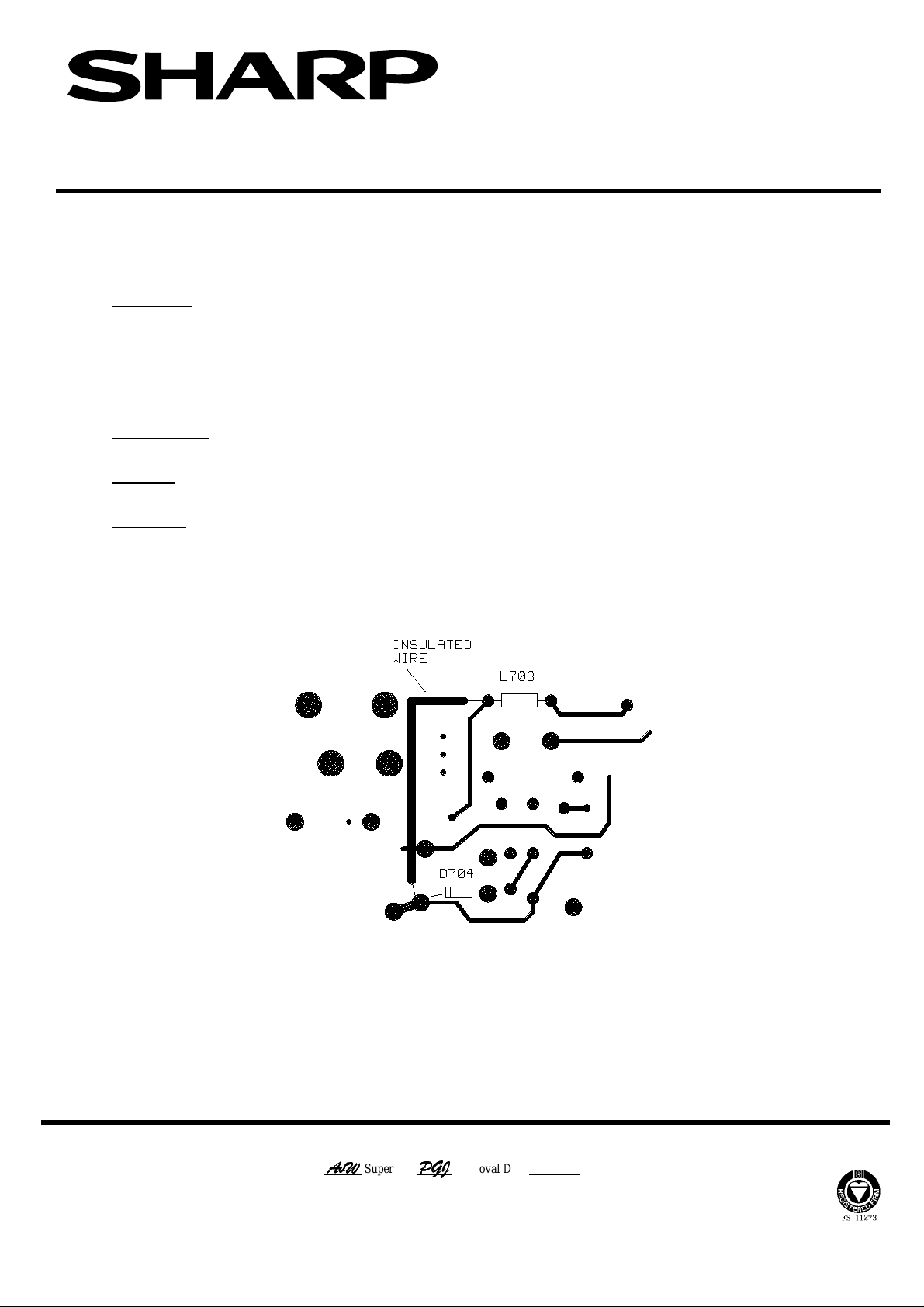
If there is no 300VDC across C708, t hen check the continuity between L703 and
the cathode o f D704. If this is open circuit, fit a wire link between the two po ints
as indicated in the diagram below.
Page 1 of 1
Location of wire link on the component side of the PWB
Sharp Electronics (UK) Limited CE Technical Support Group
$Y:
Originator
White - Carry out as required Yellow - Carry out as required and whenever unit co mes in for service Red - Carry out on all units
$Y:
Supervisor
3*-
Approval Date 10/ 02/97 UK 64601Y
3*-
Page 2
CTV970202
Date of Issue : 10/02/97
Cla ssification : Yello w
TELEVISION TECHNICAL BULLETIN
MODELS 51CS03H 51CS05H 59CS03H
59CS05H 66CS03H 66CS05H
SYMPTOM
ACTION
If there is a failure of any component within the vertical deflection circuit or
if a s et comes in fo r service th en carry o ut the improvement detailed below.
1. Add a new diode ( 1N4148 ) from the emitter of Q509 to the cathode of D513,
cathode of diode to the emitter of Q509.
2. Replace R534 with a 390R.
3. Solder a fuse ( QFS-J1023CEZZ ) in series with L607.
4. Solder a fuse ( QFS-J1023CEZZ ) in series with L608.
Page 1 of 2
Refer to the diagrams given below.
REF NO DESCRIPTION PART NUMBER PRICE CODE
- Diode, 1N4148 RH-DX0045BMZZ AA
R534 Resistor , 390R 1/10W VRS-TV1JD331J AA
- Fuse, 1A QFS-J1023CEZZ AA
Sharp Electronics (UK) Limited CE Technical Support Group
$Y:
Originator
White - Carry out as required Yellow - Carry out as required and whenever unit co mes in for service Red - Carry out on all units
$Y:
Supervisor
3*-
Approval Date 10/ 02/97 SP64500X
3*-
Page 3
CTV970203
Date of Issue : 10/02/97
Cla ssification : Yello w
TELEVISION TECHNICAL BULLETIN
MODELS 51CS03H 59CS03H 66CS03H
51CS05H 59CS05H
SYMPTOM
CAUSE
ACTION
When used in a hot environment a bleeping sound may be heard from the speakers or
t here is intermittent soun d los s.
Pin 22 of IC301 floating.
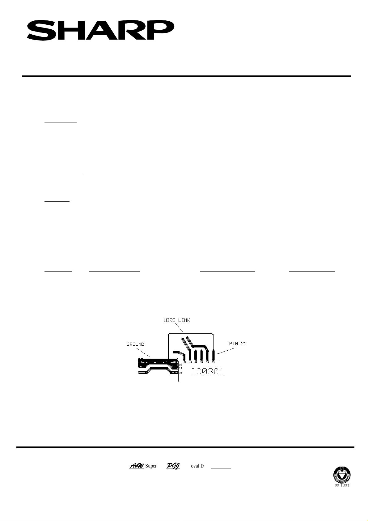
Insert wire link between pin 22 of IC301 and ground as indicated in the diagram
below.
To make the insertion of this link easier remove X301, fit wire, then replace
X301.
Page 1 of 1
REF NO DESCRIPTION PART NUMBER PRICE CODE
- Wire Link, 20mm VW7UGB0-020AA AA
Location of wire link on component side of PWB
Sharp Electronics (UK) Limited CE Technical Support Group
$Y:
Originator
White - Carry out as required Yellow - Carry out as required and whenever unit co mes in for service Red - Carry out on all units
$Y:
Supervisor
3*-
Approval Date 10/ 02/97 GE64801X
3*-
Page 4

CTV980204
Month of Issue : February 1998
Classification : White
TELEVISION TECHNICAL BULLETIN
MODELS 51CS03H 51CS05H 59CS03H
59CS05H 59CSD8H 66CS03H
66CS05H 66CSD8H
SYMPTOM
CAUSE
ACTION
REF NO DESCRIPTION PART NUMBER PRICE CODE
Intermittent sound. May be especially noticeable on channel change.
Erratic response of the multi-standards processor, I C301.
Connect a 47nF, 63V polyester capacitor from pin 61 of IC301 to gr ound.
Use the part number given below for the capacitor.
Page 1 of 1
- Capacitor, 47nF 63V RC-FZ9473BMNJ AC
Sharp Electronics (UK) Limited CE Technical Support Group
$Y:
Originator
White - Carry out as required Yellow - Carry out as required and whenever unit co mes in for service Red - Carry out on all units
$Y:
Supervisor
Approval Date / / Reference G E73703X
Page 5

C
TV980602
Month of Issue : June 1998
Classification : W h ite
TELEVISION TECHNICAL BULLETIN
MODELS 51CS03H 51CS05H 59CS03H
59CS05H 66CS03H 66CS05H
59CSD8H 66CSD8H
SYMPTOM
CAUSE
ACTION
Intermittent vertical linearity problems or partial loss of vertical scan.
Failure of components in the vertical output stage.
Replace the following components in the vertical output stage:C506 and C507.
D501, D502, D507 and D512
Q507, Q508 and Q512
Page 1 of 1
Use the part numbers given below for these parts.
Note that there are no part numbers in the service manual for C506 and C507.
These are both 22nF SMD capacitors and should be sourced locally.
REF NO DESCRIPTION PART NUMBER PRICE CODE
D501 Zener Diode, 18V RH-EX0558BMZZ AA
D502 Zener Diode, 18V RH-EX0558BMZZ AA
D507 Diode, 1N4934 RH-DX0504BMZZ AA
D512 Diode, 1N4934 RH-DX0504BMZZ AA
Q507 Transistor RH-TX0147BMZZ AD
Q508 Transistor RH-TX0151BMZZ AD
Q512 Transistor RH-TX0150BMZZ AC
Sharp Electronics (UK) Limited CE Technical Support Group
Originator
White - Carry out as requ ired Yellow - Carry out as required and whenever unit co mes in for service Red - Carry out on all units
$Y:
$Y:
Superv isor
Approval Date / / Reference 98269HT
Page 6
C
TV980603
Month of Issue : June 1998
Classification : W h ite
TELEVISION TECHNICAL BULLETIN
MODELS 51CS03H 59CS03H 66CS03H
REASON
ACTION
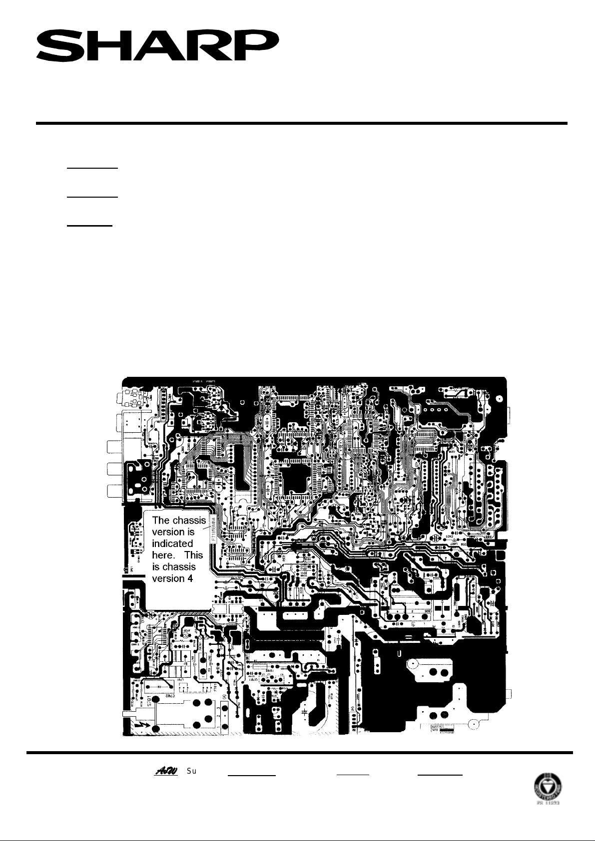
From version 4 of this chassis, various changes have been made to the circuit.
When servicing chassis versions 4 or greater ( see diagram below) use the
51CS05H ( Part number SEKL51CS05H/1 ) or the 59/66CS05H ( Part number
SEKT66CS05H/2 ) service manuals.
Changes to the 51CS03H, 59CS03H and 66CS03H circuitry are :-
1. An audio mute circuit now incorporated into the chassis.
2. R631 and R632 have been added in series to the vertical +/-13V supplies.
For the 59CS03H and 66CS03H only R628, D616 and D621 have been added
to the +45V supply line from the line output transformer.
Page 1 of 1
Sharp Electronics (UK) Limited CE Technical Support Group
Originator
White - Carry out as requ ired Yellow - Carry out as required and whenever unit co mes in for service Red - Carry out on all units
$Y:
$Y:
Superv isor
Approval Date / / Reference AM 110398
Page 7
C
TV980605
Month of Issue : June 1998
Classification : W h ite
TELEVISION TECHNICAL BULLETIN
MODELS 66CS03H 59CS03H 59CSD8H
REASON
ACTION
Due to a running change during production, the loudspeaker has been
changed for a smaller type.
When fitting the new, small speaker in place of the larger type, a holder has
to be fitted following the procedure outlined below.
1. Remove the old speaker.
2. Stick the adhesive foam to the speaker holder.
3. Fit the new speaker into the plastic holder.
4. Fit the new speaker and holder into the cabinet.
Page 1 of 1
REF NO DESCRIPTION PART NUMBER PRICE CODE
- Loudspeaker VSP1306PB067S AR
- Speaker holder GBFL-1003BM00 AD
- Adhesive foam PMLT-1032BM00 AC
Sharp Electronics (UK) Limited CE Technical Support Group
Originator
White - Carry out as requ ired Yellow - Carry out as required and whenever unit co mes in for service Red - Carry out on all units
Supervisor Approval Date / / Refe rence FR81100X
$Y:
$Y:
Page 8

CTV970204
Date of Issue : 10/02/97
Classification : White
TELEVISION TECHNICAL BULLETIN
MODELS 51CS03H 59CS03H 66CS03H
SYMPTOM
CAUSE
ACTION
If used in a hot environment, the picture can become saturated with red, green
or blue blanking lines.
Build up of flux around tr ansisto r s on the CRT So cket PWB, causing tracking
between them.
1. Remove SMD transistors Q870, Q871 and Q872.
2. Clean the exposed areas with a bristle brush impregnated with alcohol.
3. Clean the SMD transistor s with alcohol.
4. Replace the transistors.
Page 1 of 1
Sharp Electronics (UK) Limited CE Technical Support Group
$Y:
Originator
White - Carry out as required Yellow - Carry out as required and whenever unit co mes in for service Red - Carry out on all units
$Y:
Supervisor
3*-
Approval Date 10/ 02/97 GE64802X
3*-
Page 9

CTV970207
Date of Issue : 10/02/97
Classification : White
TELEVISION TECHNICAL BULLETIN
MODELS 51CS03H 59CS03H 66CS03H
SYMPTOM
CAUSE
ACTION
No or intermittent vertical output.
Intermittent so lder joint on L501.
Resolder joint on L501 as shown in the diagram below.
Page 1 of 1
Points to resolder on L501
Sharp Electronics (UK) Limited CE Technical Support Group
$Y:
Originator
White - Carry out as required Yellow - Carry out as required and whenever unit co mes in for service Red - Carry out on all units
$Y:
Supervisor
3*-
Approval Date 10/ 02/97 UK 70200X
3*-
Page 10

CTV990113
ge)
Month of Issue: January 1998
Classification: White
TELEVISION TECHNICAL BULLETIN
Page 1 of 2
MODELS 51CS03H 51CS05H 59CS03H 59CS05H
59CSD8H 66CS03H 66CS05H 66CSD8H
Symptom Possible Remedy
Dead no sound or vision)
Q701 & Q601 failed * D609, D610, D720, D718, Q702, Q703, C601, C604,
C619, C714, C708, R706, R707, R720 and inspect scan
coils and scan coil socket for bad connections.
Q601 failed D609, D610, C601, C604, C619 and inspect scan
coils/scan coil socket for bad connections.
Q601 s/c and failur e of audio o/p stage Q601 failed due t o missing - 16V rail (supply to o/p
. Leave Q601 out of circuit until you have
sta
confirmed that both the +16V and the -16V rails are
correct.
No voltage at Q701 drain
NICAM LED on or flashing (aerial disconnected) See flowchart on page 2
Technical Bulletin CTV970201
(Issued Feb 97)
HT rail present, no li ne drive, NICAM LED switches on for
3-6 seconds then goes off ( ari el disconnected)
Keeps switchi ng to standby Check audio output stage for a short circuit
HT rail missing-unsolder pin 2 of
LOPTX and measure the HT rail
Line drive pulsating IC401 not communicating with micro
Line drive pulsating and R628 (R634 in later Q704 (low standby/sound 5V rail)
models) burning
Slow start up i.e. more t han 3- 6 seconds for
line oscillator to start depending on model
Audio Problems
Intermittent sound Technical Bulletin CTV970203 or CTV980204
Whistle on the Audio (l ater models only) Damage print feeding 40V to R368
Distorted sound IC301 (MSP3410)
Vertical O/P Stage Faults
No or intermitt ent ver tical output T ec hnical Bulletin CTV970207 (I ssued F eb 97)
Failure of verti c al output stage Technical Bulletin CTV970202 (Issued Feb 97) &
Intermittent fram e c r am ping Replace D501, D502, D507, D512, C506 & C507
Rainbow effect (no line pulses at IC501 pin 2) C501
Rainbow effect and R628 (R634 in later models) open
circuit
0V Power supply not r unning (check CTV is not in
standby mode
20V-40V Short on one of the secondary LT supply rails e.g.
audio o/p stage
110V-150V Short circuit on line o/p stage
Check R611 and IC201
C714 (please ensure that this is replaced with the
specified part)
check Q507/8/ 9
R631 or R632 fusible resi stor s
Originator AvW Supervisor Approval Date / / Reference AVW120199/2
Sharp Electronics (UK) Limited
Revision 1
White – Carry out as required, Yellow – Carry out as required and whenever the unit comes in for service, Red – Carry out on all units
Page 11

CTV990113
(
Month of Issue: January 1998
Classification: White
TELEVISION TECHNICAL BULLETIN
Symptom Possible Remedy
Other Problems
East West correction Check D605, D612, D619, D621 & R628
later models)
Blank raster and fl y bac k li nes when hot Technical Bulletin CTV970204 ( issued Feb 97)
Blank raster ( no sandcastle pulse) D602
Tuner drift Technical Bulletin CTV970806 (Issued Feb 97)
R634 in
Page 2 of 2
Notes
1. D609 & D610 may not read faulty.
2. Q601, IC201 & C601 are diff er ent devic es i n the 51cm than the larger models.
3. Before replaci ng IC201 ensure that 8V is present on all three supply pins (22,23 & 53)
4. The value of R706 in the 59CS05 & 66CS05 models is 0.33ohm.
5. CTV must be tuned to CH69 and receiving a signal before the IF PLL (ACF) is carried out .
6. For alternativ e 45V and Audi o Mute ci r c uits (??CS)3H models only) refer to ??CSO 5H servic e m anual.
7. Some exchange PWB will hav e a single 4 pin socket instead of t wo 2 pin sockets for the loudspeaker
connections. Carefully trim the two 2 pin plug to enabl e them to fit into the single 4 pin socket .
* These parts except for R707 & R720 are available as a kit.
Part numbers are:
51 cm models
59/66cm models
Sharp Electronics (UK) Limited
Originator AvW Supervisor Approval Date / / Reference AVW120199/2
White – Carry out as required, Yellow – Carry out as required and whenever the unit comes in for service, Red – Carry out on all units
51 CSCHASSISKIT
59 CSCHASSISKIT
Revision 1
Page 12

CTV990108
Month of Issue: January 1999
Classification: White
TELEVISION TECHNICAL BULLETIN
Page 1 of 1
MODELS 51CS03H 51CS05H 59CS03H 59CS05H
59CSD8H 66CS03H 66CS05H 66CSD8H
SYMPTOM
During a fault condition, the NICAM LED may flash in a certain sequence to indicate
where the fault lies.
ACTION
The diagram below reprensents the NICAM LED flashing sequence to indicate which
part of the circuit is fualty. Note that this facilty is only avialable on later CS chassis.
Vertical deflection failure detected: 66% ON / 33% OFF and OFF for a second.
One second One second
Unable to read or write into NVM: 66% ON / 33% OFF for two times and OFF for a
second.
One second One second
MSP failure: 66% ON / 33% OFF for three times and OFF for a second
One second One second
Video IC failure: 66% ON / 33% OFF for four times and OFF for a sec.
One second One second
Originator AvW Supervisor Approval Date / / Reference JC091298
White – Carry out as required, Yellow – Carry out as required and whenever the unit comes in for service, Red – Carry out on all units
Sharp Electronics (UK) Limited
Revision 2
Page 13

CTV970806
Month of Issue: August 1997
Classification: White
TELEVISION TECHNICAL BULLETIN Page 1 of 1
MODELS 51CS03H 51CS05H 59CS03H 59CS05H
59CSD8H 66CS03H 66CS05H 66CSD8H
SYMPTOM After the set has warmed up, the AFT circuit may become unstable. This leads to the
set drifting off tune, either on one channel or all channels.
CAUSE Changes of tollerances in the AFT circuit.
ACTION Readjust the AFT circuit as descibed in the adjustment service manual.
This is duplicated below for reference.
1. Place the set in the service mode.
2. Apply a colour bar pattern to the RF input at 855.25MHz.
3. Press the standby button on the remote control.
4. The set will now undertake the AFT adustment automatically.
5. Turn the set off by the mains switch to cancel the service mode.
Sharp Electronics (UK) Limited
Reference UK72700X
Revision 1
White – Carry out as required, Yellow – Carry out as required and whenever the unit comes in for service, Red – Carry out on all units
Page 14

CTV990603
Month of Issue: June 1999
Classification: White
TELEVISION TECHNICAL BULLETIN
Page 1 of 2
MODELS 51CS03H 51CS05H 59CS03H 59CS05H
59CSD8H 66CS03H 66CS05H 66CSD8H
SYMPTOM
The receiver can suffer from any of the symptoms listed below.
• Intermittent failure of Q601
• Intermittent failure of Q701
• No start up
•
Q601 running excessively hot
ACTION
Fit the CS Chassis kit, details given below.
REF NO DESCRIPTION PART NUMBER PRICE CODE
- Kit for 51cm models 51CSCHASSISKIT AT
- Kit for 59/66cm models 59CSCHASSISKIT AV
The kits in the parts list above contain the following parts, it is strongly recommended that ALL parts
are fitted.
51CSCHASS ISKIT 59CSCHASSISKIT
C601
C604
C619
C708
C714
D609
D610
D718
D720
F701
Q601
Q701
Q702
Q703
R706
R706 VRN-VV3ABR33J For 59CS05H and 66CS05H models only
R707
RC-FZ0147BMZZ RC-FZ0152BMZZ
RC-EZ0122BMZZ RC-EZ0122BMZZ High temperature type
VCEAGA1JW107M VCEAGA1JW107M
RC-FZ9683BMNJ RC-FZ9683BMNJ
VCEAHA1AB108M VCEAHA1AB108M High temperature type
RH-DX0503BMZZ RH-DX0503BMZZ
RH-DX0504BMZZ RH-DX0504BMZZ
RH-EX0419BMZZ RH-EX0419BMZZ
RH-DX0045BMZZ RH-DX0045BMZZ
QFS-C3226CEZZ QFS-C3226CEZZ
RH-TX0125BMZZ RH-TX0144BMZZ Different transistor for 51 and 59/66cm models
RH-TX0166BMZZ RH-TX0166BMZZ
RH-TX0102BMZZ RH-TX0102BMZZ
RH-TX0102BMZZ RH-TX0102BMZZ
VRN-VV3ABR47J VRN-VV3ABR47J Not for 59CS05H or 66CS05H models
VRS-TV1JD221J VRS-TV1JD221J
Note
Notes:
Check the scan coils and scan coil plug for dry joints.
Ensure that the resistor next to C604 (R638) is at least 5mm away from the body of the capacitor.
R706 is 0.33 Ohms in the 59CS05H and 66CS05H.
The schematic diagrams on page 2 are based on the 59CSD8H.
Sharp Electronics (UK) Limited
Reference
White – Carry out as required, Yellow – Carry out as required and whenever the unit comes in for service, Red – Carry out on all units
JCJRAVW040699
Revision
1
Page 15

CTV990603
Month of Issue: June 1999
Classification: White
TELEVISION TECHNICAL BULLETIN
Page 2 of 2
Schematic Diagram Showing the Location of Components in the Power Supply
Schematic Diagram Showing the Location of Components in the Line Stage
Sharp Electronics (UK) Limited
Reference
White – Carry out as required, Yellow – Carry out as required and whenever the unit comes in for service, Red – Carry out on all units
JCJRAVW040699
Revision
1
Page 16

CTV990110
Month of Issue: January 1998
Classification: White
TELEVISION TECHNICAL BULLETIN Page 1 of 1
MODELS 51CS03H 51CS05H 59CS03H 59CS05H
66CS03H 66CS05H
SYMPTOM Doming caused by high beam current in limited areas of the CRT shadowmask
causing short term purity errors.
ACTION Reduce the customer brightness and contrast settings to a point at which doming does
not appear.
Note that these levels then need to be stored while in the user picture set up menu.
Sharp Electronics (UK) Limited
Reference JC110199/1
Revision 2
White – Carry out as required, Yellow – Carry out as required and whenever the unit comes in for service, Red – Carry out on all units
Page 17

CTV2000 01 09
Month of Issue: February 2000
Classification: White
TELEVISION TECHNICAL BULLETIN
Page 1 of 1
MODELS 51CS03H 51CS03IR 51CS05H 59CS03H
59CS03IR 59CS05H 59CSD8H 66CS03H
66CS03IR 66CS05H 66CSD8H
SYMPTOM
• Slow start up
• Intermittent text
• Intermittent OSD rolling
• Intermittent height problems
• Poor vertical linearity (cramping top or bottom of the picture)
•
Intermittent failure on the line output transistor.
CAUSE Failure of C604, C619 and/or C714.
ACTION Replace the capacitors with high temperature types.
Please use the part numbers listed below .
REF NO DESCRIPTION PART NUMBER PRICE CODE
C604
C619
C714
Capacitor 330µF, 10V 105°C
Capacitor 100µF, 63V 105°C
Capacitor 1000µF, 10V 105°C
VCEAHA1AN337M AB
VCEAHA1JN107M AC
VCEAHA1AN108M AD
FIG 1 FIG 2
Sharp Electronics (UK) Limited
Reference UK92300X
Revision
White – Carry out as required, Yellow – Carry out as required and whenever the unit comes in for service, Red – Carry out on all units
2
Page 18

CTV2000 03 03
Month of Issue: March 2000
Classification: White
TELEVISION TECHNICAL BULLETIN
Page 1 of 1
MODELS 51CS03H 51CS05H 59CS03H 59CS05H
59CSD8H 66CS03H 66CS05H 66CSD8H
SYMPTOM A bright line appears at the top of the frame (approximately one-inch down) if it is
adjusted correctly. Usually the customer complains that the frame has come down
about half an inch at the top of the picture (no fold over). This cannot be removed by
adjustment.
CAUSE Failure of C512 or C517.
ACTION Replace C512 and C517 (22uF, 25V).
Sharp Electronics (UK) Limited
Reference JC03032000-2
Revision
White – Carry out as required
Yellow – Carry out as required and whenever the unit comes in for service
Red – Carry out on all units
1
Page 19

CTV2000 04 02
Month of Issue: April 2000
Classification: White
TELEVISION TECHNICAL BULLETIN
Page 1 of 1
MODELS 51CS03H 51CS05H 59CS03H 59CS05H
59CSD8H 66CS03H 66CS05H 66CSD8H
SYMPTOM No or intermittent sound.
CAUSE D333 breaking down intermittently.
ACTION Replace D333 using the part number given below.
REF NO PART NUMBER DESCRIPTION PRICE CODE
D333 RH-EX0544BMZZ Zener diode, 4.7V AA
Sharp Electronics (UK) Limited
Reference GGN31032000-1
Revision
White – Carry out as required
Yellow – Carry out as required and whenever the unit comes in for service
Red – Carry out on all units
1
Page 20

CTV2000 06 07
Month of Issue: June 2000
Classification: White
TELEVISION TECHNICAL BULLETIN
Page 1 of 1
MODELS 51CS03H 51CS05H 59CS03H 59CS05H
59CSD8H 66CS03H 66CS05H 66CSD8H
SYMPTOM
1. Intermittent failure of one or both of the vertical supply line fuses (R631 and R632).
2. Frame rises up when warm until there is a large black band at the bottom of the
screen. This can eventually lead to the 'rainbow effect' at the top of the screen.
3. Line tripping (same symptom when the Megatext IC goes faulty).
4. Slow to come out of standby.
CAUSE
Breakdown of Q707, causing variation of the main 5V supply rail to the vertical stage
and Megatext IC.
ACTION
This problem can be checked by measuring the voltage at the emitter of Q707 during
the fault condition.
Note that Q707 can fail when C714 is replaced, so it is recommended that C714 is
changed at the same time as Q707.
REF NO DESCRIPTION PART NUMBER PRICE CODE
Q707 Transistor, BC338-40 RH-TX0218BMZZ AB
C714
Capacitor, 1000mF 10V 105°C
VCEAHA1AB108M AD
Sharp Electronics (UK) Limited
Reference JR20062000-1
Revision
White Carry out as required
Yellow Carry out as required and whenever the unit comes in for service
Red Carry out on all units
1
Page 21

Page 22

Page 23

Page 24

CTV990113
ge)
Month of Issue: January 1998
Classification: White
TELEVISION TECHNICAL BULLETIN
Page 1 of 2
MODELS 51CS03H 51CS05H 59CS03H 59CS05H
59CSD8H 66CS03H 66CS05H 66CSD8H
Symptom Possible Remedy
Dead no sound or vision)
Q701 & Q601 failed * D609, D610, D720, D718, Q702, Q703, C601, C604,
C619, C714, C708, R706, R707, R720 and inspect scan
coils and scan coil socket for bad connections.
Q601 failed D609, D610, C601, C604, C619 and inspect scan
coils/scan coil socket for bad connections.
Q601 s/c and failur e of audio o/p stage Q601 failed due t o missing - 16V rail (supply to o/p
. Leave Q601 out of circuit until you have
sta
confirmed that both the +16V and the -16V rails are
correct.
No voltage at Q701 drain
NICAM LED on or flashing (aerial disconnected) See flowchart on page 2
Technical Bulletin CTV970201
(Issued Feb 97)
HT rail present, no li ne drive, NICAM LED switches on for
3-6 seconds then goes off ( ari el disconnected)
Keeps switchi ng to standby Check audio output stage for a short circuit
HT rail missing-unsolder pin 2 of
LOPTX and measure the HT rail
Line drive pulsating IC401 not communicating with micro
Line drive pulsating and R628 (R634 in later Q704 (low standby/sound 5V rail)
models) burning
Slow start up i.e. more t han 3- 6 seconds for
line oscillator to start depending on model
Audio Problems
Intermittent sound Technical Bulletin CTV970203 or CTV980204
Whistle on the Audio (l ater models only) Damage print feeding 40V to R368
Distorted sound IC301 (MSP3410)
Vertical O/P Stage Faults
No or intermitt ent ver tical output T ec hnical Bulletin CTV970207 (I ssued F eb 97)
Failure of verti c al output stage Technical Bulletin CTV970202 (Issued Feb 97) &
Intermittent fram e c r am ping Replace D501, D502, D507, D512, C506 & C507
Rainbow effect (no line pulses at IC501 pin 2) C501
Rainbow effect and R628 (R634 in later models) open
circuit
0V Power supply not r unning (check CTV is not in
standby mode
20V-40V Short on one of the secondary LT supply rails e.g.
audio o/p stage
110V-150V Short circuit on line o/p stage
Check R611 and IC201
C714 (please ensure that this is replaced with the
specified part)
check Q507/8/ 9
R631 or R632 fusible resi stor s
Originator AvW Supervisor Approval Date / / Reference AVW120199/2
Sharp Electronics (UK) Limited
Revision 1
White – Carry out as required, Yellow – Carry out as required and whenever the unit comes in for service, Red – Carry out on all units
Page 25

CTV990113
(
Month of Issue: January 1998
Classification: White
TELEVISION TECHNICAL BULLETIN
Symptom Possible Remedy
Other Problems
East West correction Check D605, D612, D619, D621 & R628
later models)
Blank raster and fl y bac k li nes when hot Technical Bulletin CTV970204 ( issued Feb 97)
Blank raster ( no sandcastle pulse) D602
Tuner drift Technical Bulletin CTV970806 (Issued Feb 97)
R634 in
Page 2 of 2
Notes
1. D609 & D610 may not read faulty.
2. Q601, IC201 & C601 are diff er ent devic es i n the 51cm than the larger models.
3. Before replaci ng IC201 ensure that 8V is present on all three supply pins (22,23 & 53)
4. The value of R706 in the 59CS05 & 66CS05 models is 0.33ohm.
5. CTV must be tuned to CH69 and receiving a signal before the IF PLL (ACF) is carried out .
6. For alternativ e 45V and Audi o Mute ci r c uits (??CS)3H models only) refer to ??CSO 5H servic e m anual.
7. Some exchange PWB will hav e a single 4 pin socket instead of t wo 2 pin sockets for the loudspeaker
connections. Carefully trim the two 2 pin plug to enabl e them to fit into the single 4 pin socket .
* These parts except for R707 & R720 are available as a kit.
Part numbers are:
51 cm models
59/66cm models
Sharp Electronics (UK) Limited
Originator AvW Supervisor Approval Date / / Reference AVW120199/2
White – Carry out as required, Yellow – Carry out as required and whenever the unit comes in for service, Red – Carry out on all units
51 CSCHASSISKIT
59 CSCHASSISKIT
Revision 1
Page 26

Page 27

Page 28

Page 29

Page 30

CTV990203
Month of Issue: Febuary 1999
Classification: White
TELEVISION TECHNICAL BULLETIN Page 1 of 1
MODELS 51DS02H 51DS03H 51DS05H 59DS03H
59DS05H 66DS03H 66DS05H 66ES05H
Common Faults on the CA10 chassis
Fault Reason Cause
No functions - set will not turn on Supply to IC702 missing R704 open circuit
Set not coming out of standby Start up pulse missing R713/4 open circuit or high
Vertical scanning problems No supply to vertical output stage F601 and/or F602 (note that both these
fuses shoulc be 1.5A)
Child lock problems Programming error Go into the service mode and select
Auto Installion On, then restart set.
No or intermittent response from the
remote control and/or front buttons
Set locks up No response from the slave micro R704 and/or R705 high resistance
Circuit changes around IC201 IC201 has been changed in production Refer to Technical Bulletin CTV980809
Other circuit changes Change of CRT type to Thompson Refer to Technical Bulletin CTV981203
No response from the slave micro R704 and/or R705 high resistance
or CTV981204
When replacing R704, R705, R713 or R714 please ensure that 1W resistors are used.
Note that the CA1\CA10 chassis training course notes are available on the Sharp Electronics (UK) Limited Web Site
(www.tradenet.sharp.co.uk/tech) under the models fitted with these chassis - grouped under the Service Manual
heading. These notes contain in depth details on circuit operation. Please refer to these while fault finding.
If you have a fault to add to the above list, please do no hesitate to contact Sharp Technical Support via the Hot Line
telephone number.
Sharp Electronics (UK) Limited
Reference AVW150299/2
Revision 6
White – Carry out as required, Yellow – Carry out as required and whenever the unit comes in for service, Red – Carry out on all units
Page 31

&79
0RQWKRI,VVXH $XJXVW
&ODVVLILFDWLRQ <HOORZ
7(/(9,6,217(&+1,&$/%8//(7,1
3DJHRI
02'(/6 '6+ '6+ '6+ '6+
'6+ '6+ '6+ (6+
(6+ (6'+ (6'+
6<03720
&$86(
$&7,21
7KHUHFHLYHUGRHVQRWFRPHRXWRIVWDQGE\SRZHUVXSSO\LQRSHUDWLYH
5DQGRU5JRLQJKLJKRURSHQFLUFXLW
5HSODFH5DQG5ZLWKN:×:PHWDOILOPUHVLVWRUV
8VHWKHSDUWQXPEHUVEHORZ
5()12 '(6&5,37,21 3$57180%(5 35,&(&2'(
5
5
5HVLVWRUN:×:PHWDOILOP
5HVLVWRUN:×:PHWDOILOP
95&0$+*- $$
95&0$+*- $$
6KDUS(OHFWURQLFV8./LPLWHG
5HIHUHQFH8.;
5HYLVLRQ
:KLWH¤&DUU\RXWDVUHTXLUHG
<HOORZ¤&DUU\RXWDVUHTXLUHGDQGZKHQHYHUWKHXQLWFRPHVLQIRUVHUYLFH
5HG¤&DUU\RXWRQDOOXQLWV
Page 32

 Loading...