

Page 1
ADJUSTMENT PRECAUTIONS
SERVICE MODE
This model’s setting are adjusted in two different ways: though the I2C bus control and in the
conventional analog manner. The adjustments via the I2C bus control include preset-only items
and variable data.
1. Setting the service mode by the microprocessor.
1 Make a short-circuit JA373 and JA374, enter into the service mode. (Adjustment through
the I2C bus control). (Use JWS Key to set as well).
2 Press the CH DOWN / UP key on the remote controller to get ready to select the mode
one by one.
3 Press the CH DOWN / UP key on the remote controller to select the modes reversibly
one by one.
4 Using the VOLUME UP/ DOWN key on the remote controller, the data can be modified.
5 When the short circuit between JA373 and JA374 is cut off, it will be released from the
service mode.
2. Factory Presetting.
1 Make a short-circuit JA373 and JA374 and turn on the main power switch. Initial values
are automatically preset, only when a new EEPROM is used (Judge with the first 4
bytes).
2 The initial data are preset as listed in page.
3
3 Make sure the data need modify or not (Initial data).
Note: Once the chassis has been assembly together and ready to be POWER ON for the
FIRST TIME, make sure to make a short-circuit JA373 and JA374 to switch to the
service mode position first and then turn on the main power switch. (See 2-1 above).
Precaution: If haven’t done this initiation, it may possibly generate excessive Beam
current.
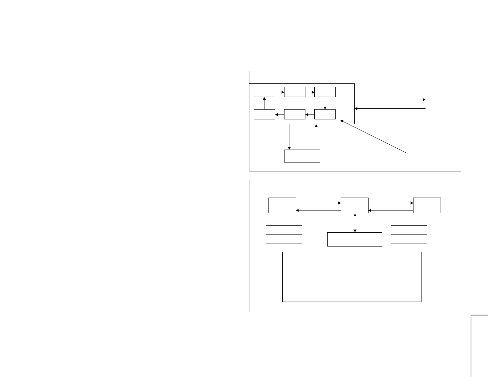
1.) In the Service Mode, Key is used to select the mode in the following order.
SERVICE MODE 1
RASTER
MODE
SUB 2 ADJ.
MODE
Press the MENU button
at the remote controller,
it will enter into
Service Mode Option.
CUT OFF
MODE
60 Hz ADJ.
MODE
SERVICE MODE
OPTION
50Hz ADJ.
MODE
SUB 1 ADJ.
MODE
Press the MENU button
again at the remote controller,
it will jump back to
Service Mode 1.
Press service/ language for 2 sec,
it will enter into service mode 2.
Press service/ language for 2 sec again,
it will jump back to service mode 1.
FORWARD : CH DOWN KEY
REVERSE : CH UP KEY
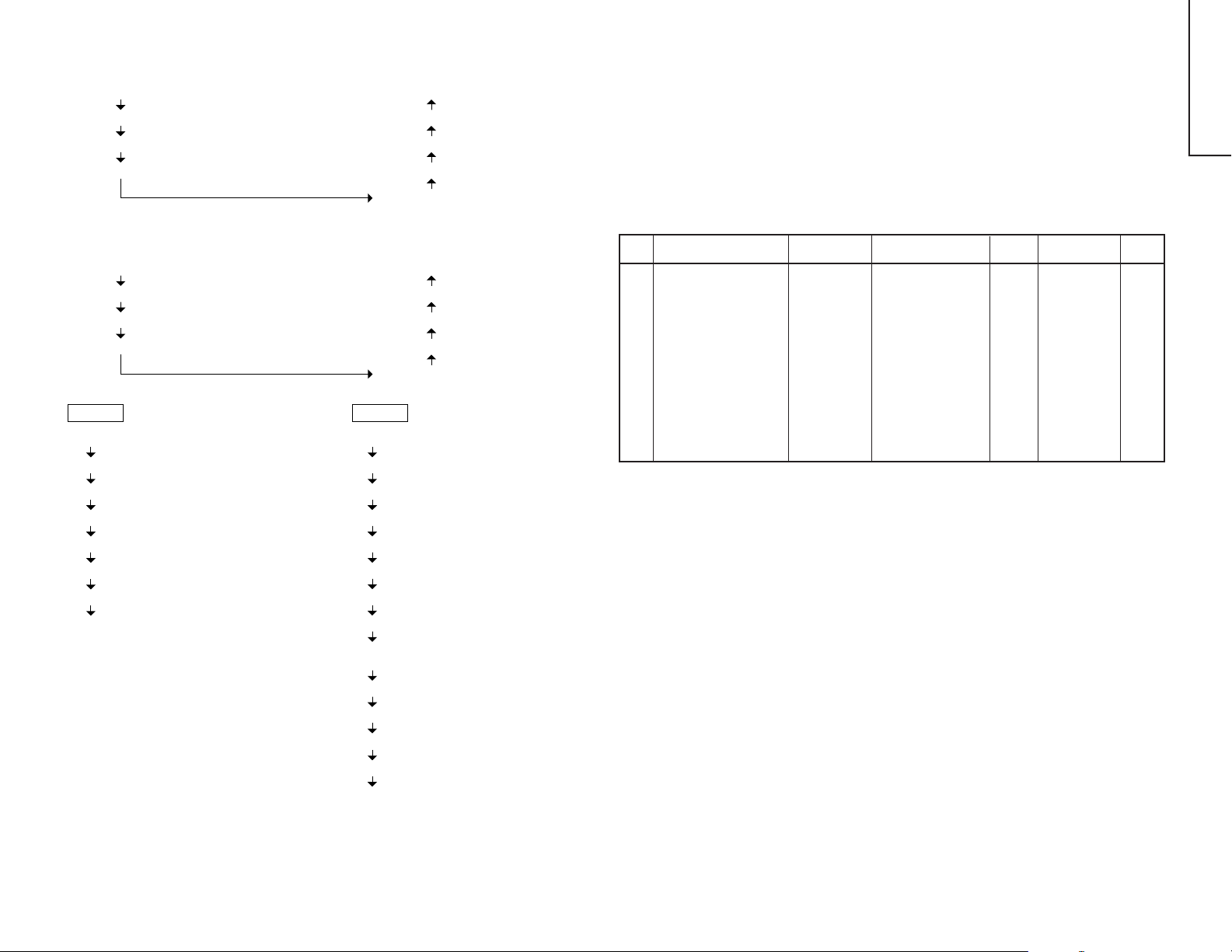
SERVICE MODE 2
CUT OFF/ BKGD MODE
R-CUT OFF
G-CUT OFF
B-CUT OFF
CUT OFF
DATA
LENGTH
63 - 255 63
INITIAL
DATA
3 sec. TIME OUT
CUT OFF
BKGD
MODE
LATERAL MODE
(R, G, B-CUT OFF)
"—/——"
3 sec. TIME OUT
DATA
LENGTH
0 - 127 63
DRIVE
G-DRIVE
B-DRIVE
INITIAL
DATA
KEY
R-CUT OFF
G-CUT OFF
B-CUT OFF
G-DRIVE
B-DRIVE
UP
1 KEY
2 KEY
3 KEY
7 KEY
8 KEY
3-1 3-2
DOWN
4 KEY
5 KEY
6 KEY
F/B KEY
0 KEY
29WF50
Page 2
50 Hz ADJ. MODE
SERVICE MODE
29WF50
V-SIZE 50 Hz (V-SIZE 50)
V-LINEARITY 50 Hz (V-LINE 50)
VS-CORRECTION 50 Hz (VS-CORR 50)
V-POSITION 50 Hz (V-CENT 50)
V-SIZE 60 Hz (V-SIZE 60)
V-LINEARITY 60 Hz (V-LINE 60)
VS-CORRECTION 60 Hz (VS-CORR 60)
V-POSITION 60 Hz (V-CENT 60)
SUB 1
4
SECAM R-Y (SCM R-Y)
SECAM B-Y (SCM B-Y)
BRIGHT (SUB BRI)
BRIGHT (DVD) (SUB BRI DVD)
SUB CONT (SUB CONT)
SUB CONT (DVD) (SUB CONT DVD)
SUB TINT (SUB TINT)
SUB TINT (DVD) (SUB TINT DVD)
FORWARD : CH DOWN KEY
REVERSE : CH UP KEY
60 Hz ADJ. MODE
TRAPEZIUM 50 Hz (TRAPE 50)
E/W CORNER 50 Hz (E/W COR 50)
E/W PARABOLA 50 Hz (E/W PAR 50)
H-SIZE 50 Hz (H-SIZE 50)
H-POSITION 50 Hz (H-CENT 50)
TRAPEZIUM 60 Hz (TRAPE 60)
E/W CORNER 60 Hz (E/W COR 60)
E/W PARABOLA 60 Hz (E/W PAR 60)
H-SIZE 60 Hz (H-SIZE 60)
H-POSITION 60 Hz (H-CENT 60)
SUB 2
SUB COLOR (SUB COLOR)
SUB COLOR (DVD) (SUB COLOR DVD)
V-ENT (V-ENT)
H-ENT (H-ENT)
RF AGC (RF AGC)
SECAM BELL (SCM BELL)
SPRIT/INTER (S/I)
RF SUB SOUND (RF S-SOUND)
HEAD PHONE (HP SUB VOL)
SUB VOLUME ADJ.
COLOR TEMP. (WT)
PIFVCO (PIFVCO)
LNA (LNA)
SIF 574 (SIF 574)
AFC (AFC)
User Data in Service Mode Option
• While SERVICE MODE 1 on, EEPROM DATA will switch to the service data.
Also, once press the menu button at the remote controller, EEPROM will switch
to SERVICE MODE OPTION.
Once press the menu button again at the remote controller, EEPROM will switch
back to SERVICE MODE 1.
• In the service option the user data establish as below,
Service Mode Option
No. EEPROM ITEM DATA LENGTH OSD IC DATA SETTING INITIAL
DATA
1 COMB OPTION ON/OFF COMB OP OPTION OFF
2 DVD OPTION ON/OFF DVD OP OPTION OFF
3 PAL OPTION ON/OFF PAL OP OPTION ON
4 6.5 M SIF FIX 0 ~ 1 6.5 M 1 CHIP 6.5 M SIF FIX (0) 0
5 ROTATION OPTION ON/OFF ROTA OP OPTION OFF
6 SYAKIT OPTION ON/OFF SYAKIT OP OPTION OFF
7 SPATIALIZER OPTION ON/OFF SPA OP OPTION OFF
8 FLAT OPTION ON/OFF FLAT OP OPTION (ON:FLAT) OFF
9 SPEAKER 1 ~ 4 SPEAKER OPTION SP1 (1) 1
10 HOTEL ON/OFF ON/OFF H MODE OPTION OFF
11 HOTEL POSITION 0 ~ 99 H POSITION OPTION 0
12 HOTEL VOLUME 0 ~ 60 H VOLUME OPTION 0
13 LANGUAGE OPTION 1 ~ 2 LANGUAGE OPTION 2
14 MONO BILINGUAL ON/OFF MO/BIL OPTION ON OFF
4-1 4-2
Page 3
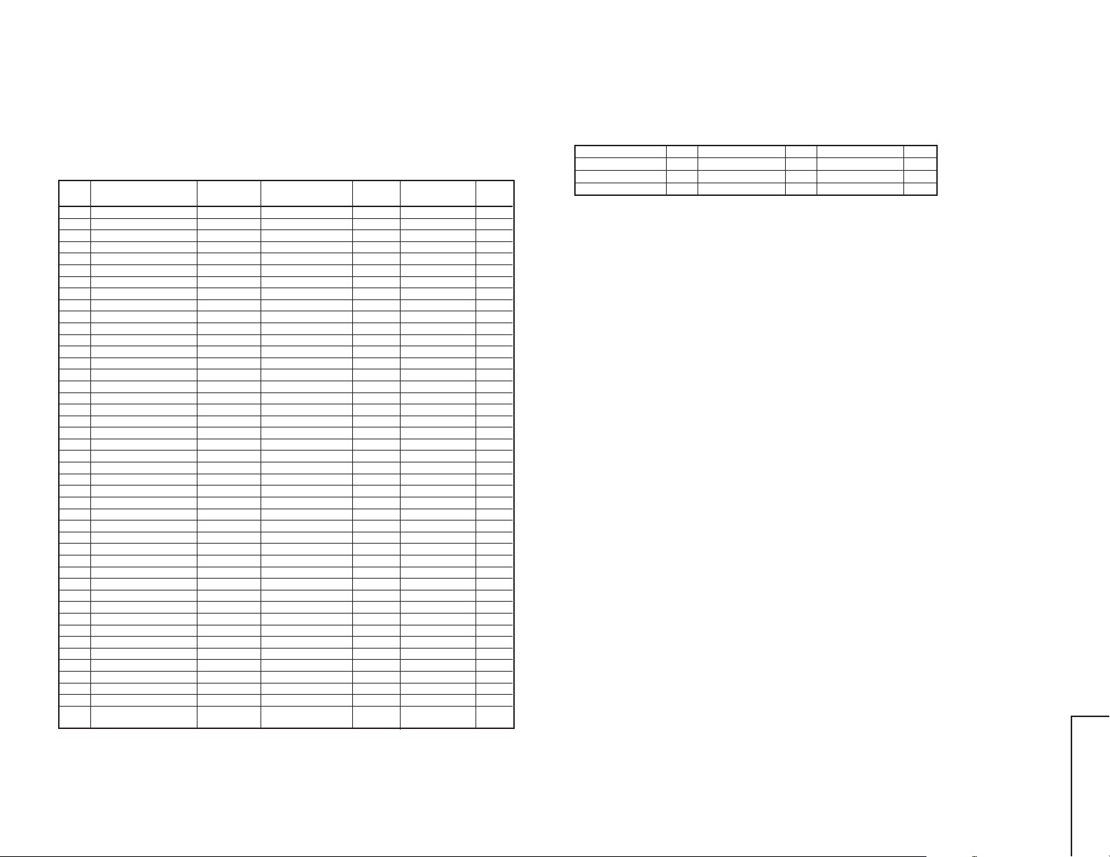
After short JA373 & JA374, and turn on the main power switch, read data from EEPROM Address
00H ~ 03H, and compare to the list below, if different, initialize the EEPROM.
Address Data Address Data
00H 23H 02H 18H
01H 23H 03H A3H
1. SERVICE MODE 1
No. EEPROM SETTING
0 MICOM INFO. DISPLAY SERVICE MODE
1 CUT OFF REFER # CUTOFF BKGD
2 CUT OFF (DVD) REFER # CUTOFFBKGD (DVD)
3 V-SIZE 0 ~ 63 V-SIZE 50 1 CHIP V-SIZE 30
4 V-LINEARITY (50Hz) #2 0 ~ 15 V S-LINE 50 1 CHIP V-LINEARITY 10
5
VS-CORRECTION (50Hz) #2
6 V-POSITION #2 0 ~ 7 V-CENT 50 1 CHIP V-PHASE 5
7 H-POSITION #2 0 ~ 31 H-CENT 50 1 CHIP H-PHASE 11
8 H-SIZE (50Hz) #2 0 ~ 63 H-SIZE 50 1 CHIP H-SIZE 32
9
E/W-PARABOLA (50Hz) #2
10 E/W CORNER (50Hz) #2 0 ~ 15 E/W COR 50 1 CHIP E/W CORNER 6
11 TRAPEZIUM (50Hz) #2 0 ~ 31 TRAPE 50 1 CHIP TRAPEZIUM 17
12 SECAM R-Y #3 0 ~ 15 SCM R-Y 1 CHIP SR-Y 8
13 SECAM B-Y #3 0 ~ 15 SCM B-Y 1 CHIP SB-Y 8
14 BRIGHT 0 ~ 127 SUB BRI 1 CHIP BRIGHTNESS 80
15 BRIGHT (DVD) 0 ~ 127 SUB BRI DVD 1 CHIP BRIGHTNESS 80
16 SUB CONT 0 ~ 15 SUB CONT 1 CHIP SUB CONT 3
17 SUB CONT (DVD) 0 ~ 15 SUB CONT DVD 1 CHIP SUB CONT 3
18 TINT 0 ~ 127 SUB TINT 1 CHIP TINT 64
19 TINT (DVD) 0 ~ 127 SUB TINT DVD 1 CHIP TINT 16
5
20 V-SIZE 0 ~ 63 V-SIZE 60 1 CHIP V-SIZE 39
21 V-LINEARITY 0 ~ 15 V-LINE 60 1 CHIP V-LINEARITY 10
22 VS-CORRECTION (60Hz) 0 ~ 15 V S-CORR 60 1 CHIP
23 V-POSITION (60Hz) 0 ~ 7 V-CENT 60 1 CHIP V-PHASE 2
24 H-POSITION (60Hz) 0 ~ 31 H-CENT 60 1 CHIP H-PHASE 14
25 H-SIZE (60Hz) 0 ~ 63 H-SIZE 60 1 CHIP H-SIZE 34
26 E/W PARABOLA (60Hz) 0 ~ 63 E/W PAR 60 1 CHIP E/W PARABORA 19
27 E/W CORNER (60Hz) 0 ~ 15 E/W COT 60 1 CHIP E/W CORNER 4
28 TRAPEZIUM (60Hz) 0 ~ 31 TRAPE 60 1 CHIP TRAPEZIUM 6
29 COLOUR 0 ~ 127 SUB COL 1 CHIP COLOUR 60
30 COLOUR (DVD) 0 ~ 127 SUB COL DVD 1 CHIP COLOUR 60
31 V-ENT 0 ~ 7 V-ENT 1 CHIP V-ENT 6
32 H-ENT 0 ~ 7 H-ENT 1 CHIP H-ENT 4
33 RF AGC 0 ~ 63 RF AGC 1 CHIP RF AGC 46
34 SECAM BELL 0 ~ 1 SCM BELL 1 CHIP S BELL 0
35 SPRIT/INTER 0 ~ 1 S/I 1 CHIP SPRIT/INTER 0
36 RF SUB SOUND 0 ~ 127 RF S-SOUND 1 CHIP RF SUB SOUND 96
37 SUB VOLUME 0 ~ 63 SUB VOL SOR/SPA VOLUME 45
38
H. PHONE SUB VOL. ADJ.
39 COLOUR TEMP. 0 ~ 1 WT OPTION 1
40 PIF VCO #4 PIFVCO 41 LNA ON/OFF LNA OPTION OFF
42 SIF574 ON/OFF SIF574 1 CHIP SIF574 ON
43 AFC ON/OFF AFC 1 CHIP AFC OFF:OFF OFF
DATA LENGTH
0 ~ 15 V S-CORR 50 1 CHIP
0 ~ 63 E/W PAR 50 1 CHIP E/W PARABORA 39
0 ~ 63 HP SUB VOL SOR/SPA VOLUME 63
OSD IC DATA SETTING
V S-CORRECTION
V S-CORRECTION
NORMAL:ON
INITIAL
DATA
8
9
#1 Whiles selecting SERVICE MODE 1, MICOM Version Information, SOFTWARE V ersion Informa-
tion, check some iformation will be displayed.
#2 60 Hz Adjustment Value is programmed from ± 50 Hz Adjustment value.
EEPROM SETTING DATA EEPROM SETTING DATA EEPROM SETTING DATA
V-SIZE +9 V-POSITION -3 E/W PARABOLA -20
V-LINEARITY 0 H-POSITION +3 E/W CORNER -2
VS-CORRECTION +1 H-SIZE +2 TRAPEZIUM -11
#3 While adjusting SECAM R-Y, SECAM B-Y and S BLACK of 1 chip is set to 1.
#4 While choosing PIFVCO MODE and RF AGC set to "0 0" and PIFVCO is set to "1".
5-1 5-2
29WF50
Page 4
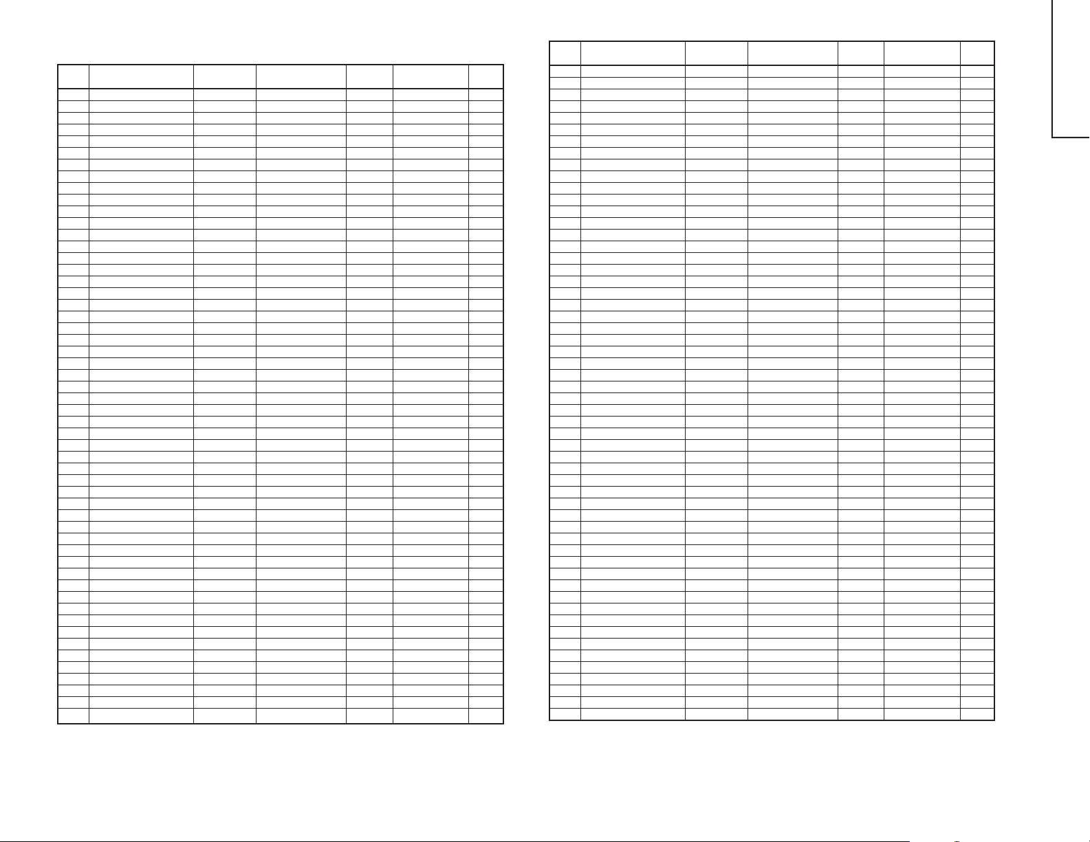
2. SERVICE MODE 2
NO. EEPROM ITEM
1 WPS 0 ~ 1 WPS 1 CHIP WPS 1
2 SUB CONTRAST 0 ~ 127 S CONT 1 CHIP CONTRAST 127
3 NTSC PHASE (NT) 0 ~ 3 N-PNT 1 CHIP NTSC PHASE 0
4 NTSC PHASE (PAL/SEC.) 0 ~ 3 N-P PS 1 CHIP NTSC PHASE 0
5 NTSC PHASE (DVD) 0 ~ 3 N-PD 1 CHIP NTSC PHASE 3
6 SUB SHARPNESS (TV) 0 ~ 63 S SHARP T 1 CHIP SHARPNESS 32
7 SUB SHARPNESS (AV) 0 ~ 63 S SHARP A 1 CHIP SHARPNESS 20
8 SUB SHARPNESS (DVD) 0 ~ 63 S SHARP D 1 CHIP SHARPNESS 10
9 RGB MUTE 0 ~ 1 RGB MUTE 1 CHIP RGB MUTE OFF
10 RGB CONTRAST 0 ~ 63 RGB CONT 1 CHIP RGB CONTRAST 32
11 Y-DL (NTSC-M) 0 ~ 3 YNM 1 CHIP Y-DL 1
12 Y-DL (PAL-B/G) 0 ~ 3 YPB 1 CHIP Y-DL 1
13 Y-DL (PAL-I) 0 ~ 3 YPI 1 CHIP Y-DL 3
14 Y-DL (PAL-D/K) 0 ~ 3 YPD 1 CHIP Y-DL 3
15 Y-DL (SECAM-B/G) 0 ~ 3 YSB 1 CHIP Y-DL 0
16 Y-DL (SECAM-D/K) 0 ~ 3 YSD 1 CHIP Y-DL 3
17 Y-DL (B/W) 0 ~ 3 YBW 1 CHIP Y-DL 0
18 Y-DL (NTSC-AV) 0 ~ 3 YNA 1 CHIP Y-DL 0
19 Y-DL (PAL-AV) 0 ~ 3 YPA 1 CHIP Y-DL 0
20 Y-DL (SECAM-AV) 0 ~ 3 YSA 1 CHIP Y-DL 0
21 Y-DL (B/W-AV) 0 ~ 3 YBA 1 CHIP Y-DL 0
22 SUB COLOUR 0 ~ 31 SUB COL 1 CHIP SUB-COLOUR 16
23 VSM GAIN AVM1 0 ~ 7 V-GAIN 1 1 CHIP VSM GAIN 3
24 VSM GAIN AVM2 0 ~ 7 V-GAIN 2 1 CHIP VSM GAIN 5
6
25 VSM GAIN AVM3 0 ~ 7 V-GAIN 3 1 CHIP VSM GAIN 7
26 BASE BAND TINT 0 ~ 31 B-B TINT 1 CHIP BASE BAND TINT 16
27 SECAM GP-PHASE 0 ~ 3 S G-PHASE 1 CHIP S SP-PHASE 1
28 SECAM ID-SENS 0 ~ 1 S ID-SENS 1 CHIP S ID-SENS 0
29 SECAM ID-MODE 0 ~ 1 S ID-MODE 1 CHIP S ID-MODE 0
30 PIF FREQ 0 ~ 7 P FREQ 1 CHIP PIF FREQ 3
31 P/N-ID 0 ~ 1 PN ID 1 CHIP P/N-ID 0
32 YS/YM MODE 0 ~ 1 YSM MODE 1 CHIP YSM MODE 1
33 RGB ABCL 0 ~ 1 RGB ABCL 1 CHIP RGB ABCL 1
34 DC RESTORATION 0 ~ 3 DC REST 1 CHIP
35 BLACK STRETCH 0 ~ 3 B ST 1 CHIP BLACK STRETCH 1
36 ABL START POINT 0 ~ 3 ABL ST 1 CHIP
37 ABL GAIN 0 ~ 3 ABL GA 1 CHIP ABL GAIN 2
38 AKB MODE 0 ~ 63 AKB MODE 1 CHIP AKB MODE 0
39 COLOUR 0 ~ 1 COL G 1 CHIP COLOUR 1
40 V AGC 0 ~ 1 V AGC 1 CHIP V AGC 0
41 V RAMP REF 0 ~ 1 V RAMP 1 CHIP V RAMP 1
42 VSM PHASE 0 ~ 1 VSM PHASE 1 CHIP VSM PHASE 0
43 BASS LEVEL ON 0 ~ 3 BA LV SUR/SPA BASS LEVEL 3
44 BASS OFF AVM1 SP1 0 ~ 4 #1 BA OFF 1 SP1 SUR/SPA BASS SW, LEVEL 4
45 BASS OFF AVM2 SP1 0 ~ 4 #1 BA OFF 2 SP1 SUR/SPA BASS SW, LEVEL 4
46 BASS OFF AVM3 SP1 0 ~ 4 #1 BA OFF 3 SP1 SUR/SPA BASS SW, LEVEL 4
47 BASS OFF AVM1 SP2 0 ~ 4 #1 BA OFF 1 SP2 SUR/SPA BASS SW, LEVEL 4
48 BASS OFF AVM2 SP2 0 ~ 4 #1 BA OFF 2 SP2 SUR/SPA BASS SW, LEVEL 4
49 BASS OFF AVM3 SP2 0 ~ 4 #1 BA OFF 3 SP2 SUR/SPA BASS SW, LEVEL 4
50 BASS OFF AVM1 SP3 0 ~ 4 #1 BA OFF 1 SP3 SUR/SPA BASS SW, LEVEL 4
51 BASS OFF AVM2 SP3 0 ~ 4 #1 BA OFF 2 SP3 SUR/SPA BASS SW, LEVEL 4
52 BASS OFF AVM3 SP3 0 ~ 4 #1 BA OFF 3 SP3 SUR/SPA BASS SW, LEVEL 4
53 BASS OFF AVM1 SP4 0 ~ 4 #1 BA OFF 1 SP4 SUR/SPA BASS SW, LEVEL 4
54 BASS OFF AVM2 SP4 0 ~ 4 #1 BA OFF 2 SP4 SUR/SPA BASS SW, LEVEL 4
DATA LENGTH
OSD IC DATA SETTING
DC RESTORATION
ABL START POINT
INITIAL
DATA
3
3
NO. EEPROM ITEM
55 BASS OFF AVM3 SP4 0 ~ 4 #1 BA OFF 3 SP4 SUR/SPA BASS SW, LEVEL 4
56 AGC SW 0 ~ 1 AGC SW SUR/SPA AGC SW ON
57 AGC ADJ 0 ~ 3 AGC AD SUR/SPA AGC ADJ 2
58 FM LEVEL #2 FM L NICAM FM LEVEL +1
59 IGR LEVEL #2 IGR L NICAM IGR LEVEL +2
60 NICAM B/G LEVEL #3 BG L NICAM NICAM B/G LEVEL -1
61 NICAM 1 LEVEL #3 I L NICAM NICAM I LEVEL +4
62 NICAL D/K LEVEL #3 DK L NICAM NICAM D/K LEVEL -1
63 LOWER ERROR 0 ~ 255 L ERR NICAM LOWER ERROR 35
64 UPPER ERROR 0 ~ 255 U ERR NICAM UPPER ERROR 70
65 IGR GAIN (9873H) #4 IGR G NICAM IGR GAIN (9873H) 0
66 NICAM SPEED 0 ~ 3 N SPEED NICAM N SPEED 2
67 INTER/EXTER 0 ~ 1 IN/EX NICAM INTER/EXTER 0
68 AUTO MUTE 0 ~ 1 AM NICAM AUTO MUTE ON
69 AGC SW ON/OFF 0 ~ 1 AGC SW NICAM AGC SW OFF
70 AGC GAIN 0 ~ 31 AGC G NICAM AGC GAIN 16
71 SYAKIT VOLUME 1 0 ~ 21 SVOL 1 SYAKIT SVOLUME 1 0
72 SYAKIT VOLUME 2 0 ~ 3 SVOL 2 SYAKIT SVOLUME 2 0
73 SYAKIT LOU 0 ~ 1 SLOU SYAKIT SLOU 1
74 SYAKIT ATT 0 ~ 7 SATT SYAKIT SATT OUT 0
75 SYAKIT BASS 0 ~ 13 SBASS SYAKIT S-BASS 6
76 SYAKIT TREBLE 0 ~ 13 STRE SYAKIT S-TREBLE 6
77 MAX LEVEL SYAKIT 1 0 ~ 5 S1MA 3
78 MAX LEVEL SYAKIT 2 0 ~ 5 S2MA 4
79 MAX LEVEL SYAKIT 3 0 ~ 5 S3MA 6
80 START LEVEL SYAKIT 1 0 ~ 63 S1ST 17
81 START LEVEL SYAKIT 2 0 ~ 63 S2ST 21
82 START LEVEL SYAKIT 3 0 ~ 63 S3ST 20
83 WIDE LEVEL SYAKIT 1 0 ~ 7 S1W1 6
84 WIDE LEVEL SYAKIT 2 0 ~ 7 S2W1 3
85 WIDE LEVEL SYAKIT 3 0 ~ 7 S3W1 3
86 STOP LEVEL SYAKIT 1 0 ~ 5 S1SP 1
87 STOP LEVEL SYAKIT 2 0 ~ 5 S2SP 1
88 STOP LEVEL SYAKIT 3 0 ~ 5 S3SP 1
89 BASS MAX SYAKIT 1 0 ~ 15 SBASS1 12
90 BASS MAX SYAKIT 2 0 ~ 15 SBASS2 11
91 BASS MAX SYAKIT 3 0 ~ 15 SBASS3 10
92 TREBLE MAX SYAKIT 1 0 ~ 15 STRE1 12
93 TREBLE MAX SYAKIT 2 0 ~ 15 STRE2 11
94 TREBLE MAX SYAKIT 3 0 ~ 15 STRE3 10
95 BASS AVM1 SP1 #6 BASS 1 SP1 -5
96 BASS AVM2 SP1 #6 BASS 2 SP1 +2
97 BASS AVM3 SP1 #6 BASS 3 SP1 +5
98 BASS AVM1 SP2 #6 BASS 1 SP2 -5
99 BASS AVM2 SP2 #6 BASS 2 SP2 0
100 BASS AVM3 SP2 #6 BASS 3 SP2 +5
101 BASS AVM1 SP3 #6 BASS 1 SP3 -5
102 BASS AVM2 SP3 #6 BASS 2 SP3 0
103 BASS AVM3 SP3 #6 BASS 3 SP3 +10
104 BASS AVM1 SP4 #6 BASS 1 SP4 -5
105 BASS AVM2 SP4 #6 BASS 2 SP4 -2
106 BASS AVM3 SP4 #6 BASS 3 SP4 +6
107 TREBLE AVM1 SP1 #6 TRE 1 SP1 -5
108 TREBLE AVM2 SP1 #6 TRE 2 SP1 0
109 TREBLE AVM3 SP1 #6 TRE 3 SP1 +5
110 TREBLE AVM1 SP2 #6 TRE 1 SP2 -5
DATA LENGTH
OSD IC DATA SETTING
6-1 6-2
INITIA
DATA
29WF50
Page 5
NO. EEPROM ITEM
EEPROM
111 TREBLE AVM2 SP2 #6 TRE 2 SP2 +2
112 TREBLE AVM3 SP2 #6 TRE 3 SP2 +8
113 TREBLE AVM1 SP3 #6 TRE 1 SP3 -10
114 TREBLE AVM2 SP3 #6 TRE 2 SP3 +1
115 TREBLE AVM3 SP3 #6 TRE 3 SP3 +5
116 TREBLE AVM1 SP4 #6 TRE 1 SP4 -10
117 TREBLE AVM2 SP4 #6 TRE 2 SP4 +3
118 TREBLE AVM3 SP4 #6 TRE 3 SP4 +6
119 BASS MODE AVM1 SP1 ON/OFF #7 BA MO 1 SP1 OFF
120 BASS MODE AVM2 SP1 ON/OFF #7 BA MO 2 SP1 OFF
121 BASS MODE AVM3 SP1 ON/OFF #7 BA MO 3 SP1 ON
122 BASS MODE AVM1 SP2 ON/OFF #7 BA MO 1 SP2 OFF
123 BASS MODE AVM2 SP2 ON/OFF #7 BA MO 2 SP2 OFF
124 BASS MODE AVM3 SP2 ON/OFF #7 BA MO 3 SP2 ON
125 BASS MODE AVM1 SP3 ON/OFF #7 BA MO 1 SP3 OFF
126 BASS MODE AVM2 SP3 ON/OFF #7 BA MO 2 SP3 OFF
127 BASS MODE AVM3 SP3 ON/OFF #7 BA MO 3 SP3 ON
128 BASS MODE AVM1 SP4 ON/OFF #7 BA MO 1 SP4 OFF
129 BASS MODE AVM2 SP4 ON/OFF #7 BA MO 2 SP4 OFF
130 BASS MODE AVM3 SP4 ON/OFF #7 BA MO 3 SP4 ON
131 CONTRAST AVM1 #8 CONT 1 55
132 CONTRAST AVM2 #8 CONT 2 57
133 CONTRAST AVM3 #8 CONT 3 60
134 CONTRAST AVM1 FL #8 CONT 1 FL 55
135 CONTRAST AVM2 FL #8 CONT 2 FL 57
7
136 CONTRAST AVM3 FL #8 CONT 3 FL 60
137 COLOUR AVM1 #9 COL 1 0
138 COLOUR AVM2 #9 COL 2 0
139 COLOUR AVM3 #9 COL 3 +10
140 COLOUR AVM1 FL #9 COL 1 FL 0
141 COLOUR AVM2 FL #9 COL 2 FL 0
142 COLOUR AVM3 FL #9 COL 3 FL +10
143 SHARP AVM1 #10 SHARP 1 -5
144 SHARP AVM2 #10 SHARP 2 0
145 SHARP AVM3 #10 SHARP 3 0
146 SHARP AVM1 FL #10 SHARP 1 FL -5
147 SHARP AVM2 FL #10 SHARP 2 FL 0
148 SHARP AVM3 FL #10 SHARP 3 FL 0
149 γ- POINT AVM1 #11 G-POINT 1 3
150 γ- POINT AVM2 #11 G-POINT 2 2
151 γ- POINT AVM3 #11 G-POINT 3 1
152 γ- POINT AVM1 FL #11 G-POINT 1 FL 3
153 γ- POINT AVM2 FL #11 G-POINT 2 FL 2
154 γ- POINT AVM3 FL #11 G-POINT 3 FL 1
155 SEARCH SPEED #12 S SPE 450
156 OSD 0 ~ 127 OSD-H 2
157 BUZZ 0 ~ 1 BUZZ 1 CHIP BUZZ 0
158 AV AFC 0 ~ 1 AV AFC 1
159 TEXT H 0 ~ 63 TEXT H TEXT 30
160 TEXT V 0 ~ 63 TEXT V TEXT 30
161 NVM NVM EEPROM
DATA LENGTH
OSD IC DATA SETTING
INITIAL
DATA
INITIAL SETTING
(1) Execute MCL 1/2 key to set the following data in EEPROM.
STTM
R/C CODE MCL 4(171:Abh)
TV-CH. CH-No. Fv (MHz) S-SYSTEM
0
1 Thai Local CH-3 55.25 PAL B/G
2 Thai Local CH-5 175.25 PAL B/G
3 Thai Local CH-7 189.25 PAL B/G
4 Thai Local CH-9 203.25 PAL B/G
5 Thai Local CH-11 217.25 PAL B/G
6 Thai Local CH-29 535.25 PAL B/G
7
8
9
10
11 STTM Factory CH-E2 48.25 PAL B/G
12 STTM Factory CH-E4 62.25 PAL B/G
13 STTM Factory CH-E8 196.25 PAL B/G
14 STTM Factory CH-E10 210.25 SECAM B/G
15 STTM Factory CH-E12 224.25 PAL B/G
16 STTM Factory CH-E21 471.25 PAL B/G
17 STTM Factory CH-E69 855.25 PAL B/G
18
19
20
21 STTM Factory CH-E12 223.95 PAL B/G
22 STTM Factory CH-E12 224.55 PAL B/G
23 STTM Factory CH-E12 223.85 PAL B/G
24 STTM Factory CH-E12 224.65 PAL B/G
25 STTM Factory CH-E12 223.75 PAL B/G
26 STTM Factory CH-E12 224.75 PAL B/G
27
28
29
30
31 STTM Factory CH-J1 91.25 NTSC M
32 STTM Factory CH-J3 103.25 NTSC M
33 STTM Factory CH-J4 171.25 NTSC M
34 STTM Factory CH-J6 183.25 NTSC M
35 STTM Factory CH-J8 193.25 NTSC M
36 STTM Factory CH-J10 205.25 NTSC M
37 STTM Factory CH-J12 217.25 NTSC M
38 STTM Factory CH-J38 621.25 NTSC M
39
29WF50
40
41
7-1 7-2
Page 6
SHIPPING SETTING AND CHECKING
(1) The following default data has been factory-set for the E2PROM.
ITEMS DATA SETTING
R/C 238(EEh)
S-SYSTEM B/G
LANGUAGE THAI
SELECT
# FACTORY-SET 8 OPERATE MCL2
LAST POWER ON
LAST TV/AV MODE TV
LAST CH CH1
FLASH BACK CH1
FAVORITE CH1 CH10
FAVORITE CH2 CH20
FAVORITE CH3 CH30
FAVORITE CH4 CH40
1 DIGIT/2 DIGIT 2 DIGIT
VOLUME 0
H/P-VOLUME 0
ROTATION 0
SAVE OFF
AV MODE 2
BALANCE 0
BLUE BACK OFF
8
AUTO SELECT ON
# SERVICE MODE DATA
ITEM DATA SETTING
MODE 1 2 3
CONTRAST # # #
COLOUR # # #
BRIGHT 0 0 0
TINT 0 0 0
SHARPNESS # # #
PEICTURE NR OFF OFF OFF
WHITE TEMP 0 0 0
SHAKIT OFF OFF OFF
BASS + # # #
SOR/SPA OFF OFF OFF
LEVEL 0 0 0
BASS # 0 #
TREBLE # 0 #
FACTORYSET 9
VM ON
TEXT 1
LNA OFF
ON TIMER OFF
ON TIMER CH NO SETTING
ON TIMER VOLUME NO SETTING
REMINDER OFF
AFT ALL CH ON
COLOUR SYSTEM ALL CH AUTO
SKIP ALL CH OFF
NICAM ON/OFF ALL CH ON
NICAM STEREO MODE ALL CH STEREO
NICAM BILINGUAL MODE ALL CH M1
NICAM MONO MODE ALL CH MONO
IGR ON/OFF ALL CH ON
IGR STEREO MODE ALL CH STEREO
IGR BILINGUAL MODE ALL CH MAIN
MONO BILINGUAL MODE SOUND1
SOFT STANDARD DYNAMIC
ITEM DATA SETTING
No.
Adjustment point
Tuner IFT
1
(PRESET)
TU200
2 RF-AGC
TAKE OVER
POINT
ADJUSTMENT
(I2C BUS
CONTROL)
3 PIF VCO COIL
ADJUSTMENT
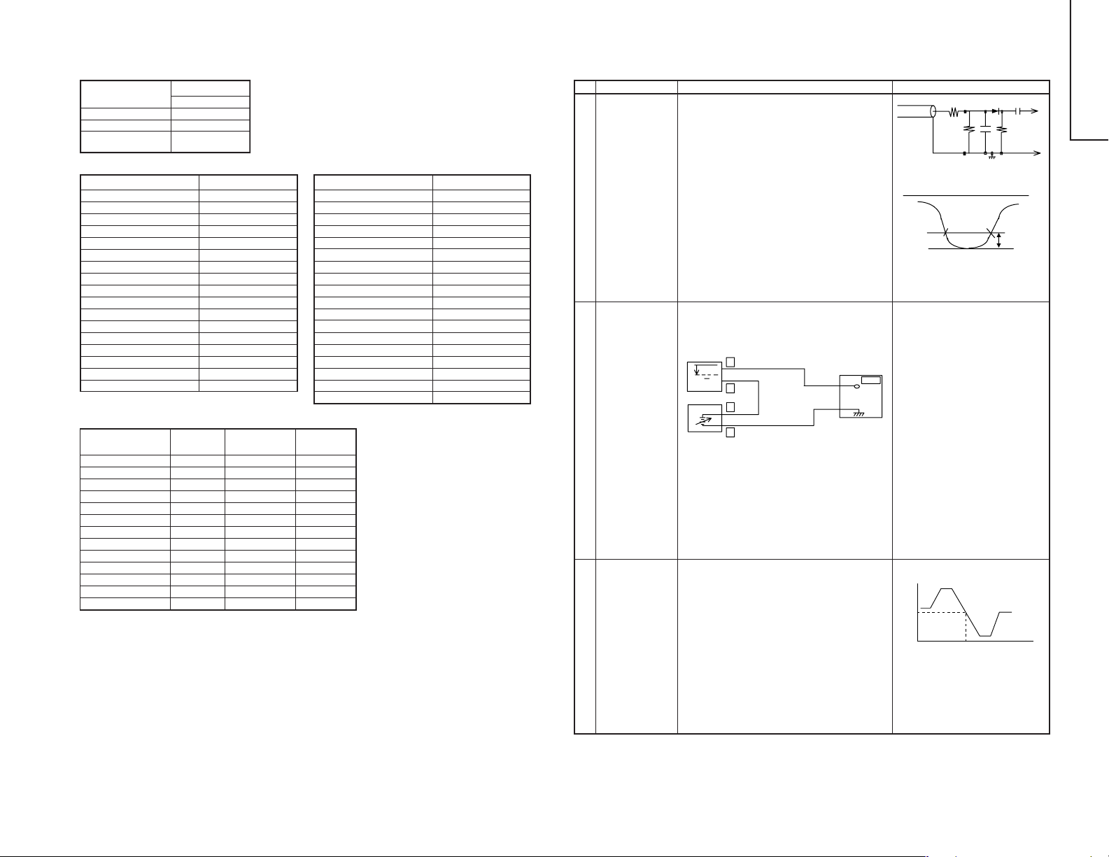
SERVICE ADJUSTMENT
PIF ADJUSTMENT CHECKING
Adjustment Condition / Procedure Waveform or others
1. Get the tuner ready to receive the CH. E-10
signal, but with no signal input.
Adjust the PLL data.
2. Connect the sweep generator’s output cable
to the tuner antenna. (RF SWEEP)
3. Adjust the sweep generator’s to 80dBµV.
4. Connect the response lead (use LOW IMPEDANCE probe with wave detector ; see Fig.1)
to the tuner’s IF output terminal. (This terminal
must have the probe alone connected).
5. Set the RF AGC to 0 - 6 V with no saturation
with the waveform.
6. Adjust the tuner IF coil to obtain the waveform
as shown in Fig. 2.
Note: Be sure to keep the tuner cover in position
during this adjustment.
1. Receive the PAL Colour bar signal.
Signal Strength: 54 ± 1 dbµV (75Ω open)
2. Connect the oscilloscope to TP201 (Tuner’s
AGC Terminal) as shown in Fig. 3.
Oscilloscope
+
0.1V
–
+
–
Bias Box : about 4.5V
BIAS Box
TP201
TV SET
Fig. 3
3. Call "RF-AGC" mode in service mode. Adjust
the "RF-AGC" bus data to obtain the Tuner output pin drop 0.1 ~ 1.0 V below maximum voltage.
4. Change the antenna input signal to 63 ~
67 dBµV, and make sure there is no noise.
5. Turn up the input signal to 90 ~ 95 dBµV to be
sure that there is no cross modulation beat.
1. Do not receive any signal.
2. Connect the digital voltmeter to TP803 (pin (54)
of IC800) in the main unit.
3. Call the "PIF VCO" Mode at the service mode.
4. Verify that it is turned counterclockwise to 0V
and adjust T800 to make DC voltage of TP803
become 2.5 ± 0.1 V in the range.
Oscilloscope
Note:
Precaution:
DC voltage at TP803
5V
2.5V
Down
Adjust T800 to B point, between B'
and B". (Point A and C is NG.)
* Turn the coil counterclockwise for
the up direction and clockwise for
the down direction.
10k
100k
P C
For the 50Ω signal strength
gauge, when not using 50/75
impedance adapter, signal
strength is 52 ± 1 dBµV (75Ω
open), instead of 54 ± 1 dBµV
(75Ω open).
The loss of using impedance
adapter.
Fig. 1
E-9 CH
Fig. 2
BB"CUPB’A
1n60
29WF50
1000p
IF OUT
75ohm
-1.5+/-0.8dB
8-1 8-2
Page 7
9
No.
Adjustment point
1 SUB VOL
(BUS
ADJUSTMENT)
2 NOISE MUTE
CHECKING
No.
Adjustment point
1 VCO COIL
T2300
(SX68KF7)
SOUND ADJUSTMENT
Adjustment Condition / Procedure Waveform or others
1. Receive PAL Colour Bar signal.
Signal content: 400 Hz 100% Mod.
2. Connect the probel of the meter (*) to (SI) connector.
3. Select the SUB-VOL in the service mode.
4. Adjust the SUB-VOL data to make the meter
indicate 5.0 Vrms (at L-CH)
Adjustment value: 5.0± 0.3 Vrms
-0.05 Vrms
1. Receive the PAL Colour Bar signal.
2. Turn up the volume control to maximum, make
sure the sound is heard from the speakers.
Then put the unit in no signal state.
3. Check the sound mute is effective.
4. Finally turn sound level of CTV to minimum.
Note:The setting below is automatically set when the SUB-VOL
is selected in the service mode.
* SURROUND OFF
* S-NORMAL state
* S-VOL Max
* Bass + OFF
SIF(NICAM/IGR) ADJUSTMENT
Adjustment Condition / Procedure Waveform or others
1. Receive the PAL Colour Bar signal.
(Set the receiving frequency at AFT OFF VHF
high frequency.)
2. Connect the digital voltmeter to TP2300 or pin
(1) of SC200 (in the main unit).
3. Verify that it is turned counterclockwise to 0V
and clockwise to 5V , and adjust T2300 to make
the DC voltage of TP2300 become 2.5 ± 0.1 V
in the range.
* Single-unit adjustment
Vcc 5 ± 0.1V
IF input frequency 38.9MHz ± 10kHz. Control it
under these conditions.
Adjust T2300 to make the DC voltage of TP2300
(in the NICAM unit) become 2.5 ± 0.1V.
After single-unit adjustment, check the practical
setup.
Align the receiving frequency to the select channel frequency. (AFT OFF)
The checked voltage must be2.5 ± 1.0V.
(Take care that ± 1.0 is considered for the Vcc
difference between the single unit and unit, Fo
difference and so on, but is not the adjustment
precision.)
No.
Adjustment point
1 PURITY
ADJUSTMENT
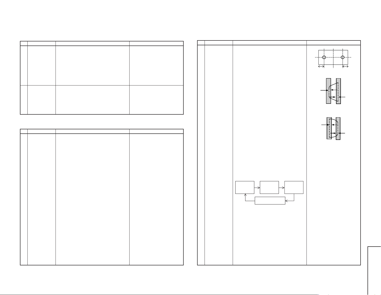
PURITY ADJUSTMENT
Adjustment Condition / Procedure Waveform or others
1. Select the green monocolour screen with remote controller, and set the beam current to
1.6mA with the contrast control.
2. Degauss the CRT enough with the degaussing coil.
Note: Follow the job instruction sheet to ad-
just the magnetic field.
*BH = 0
*Bv = refer to the job intructions sheet.
3. The purity magnet must be previously set at
the zero magnetic field and the convergence
must be roughly adjusted.
With P-Mag, adjust it to the center: rank A.
4. Observe the points a, b, as shown in Fig.4-1
through the microscope. Move DY fore and aft
to set the landing at the point (rank A).
5. If the a/b balance is poor, compensate it to the
center "Rank AB".
6. Align it to zero, keeping the raster rotation in
the east direction.
7. Tighten up the deflection coil screws.
Tightening torque : 180 ± 20N (18 ± 2Kgf)
8. Checking the CRT corner area, bond the magnet sheet to set the landing at Rank A for compensation.
Note: Apply the adjustment after aging with the
beam current 1,600 ± 50µA or more for
30 minutes or more.
Note: Select the service mode, and press the
monocolour key of R/C for process, and
the monocolour screen (green) will be
selected.
* Every push of the monocolour key, changes the
screen as follows.
Monocolour
Screen
GREEN
* Adjustment for uniformity is change to another
content. Please refer to the following page.
Monocolour
Screen
BLUE
Monocolourscreen
Release
Monocolour
Screen
RED
a
90 mm 90 mm
Fig. 4-1
A
Fig. 4-2 Rank A (On the right of CRT)
A
Fig. 4-3 Rank A (On the left of CRT)
* Continuosly press the
monocolour key 1 second or
more, and the monocolour mode
will be selected without the service mode.
b
A=B
B
B
A=B
29WF50
9-1 9-2
Page 8
10
No.
Adjustment point
1 UNIFORMITY
ADJUSTMENT
(To perform
after the purity
and convergence
adjustment)
UNIFORMITY ADJUSTMENT
Adjustment Condition / Procedure Waveform or others
Before adjustment begin, Horizontal magnetic
field=0G, Vertical magnetic field = 0.1G.
Make sure degauss it.
North Direction Red Uniformity
1. Horizontal mf = Set to monocolour screen Red
and adjust to +0.25G.
2. Pay attention to the edge of CRT, if the landing is poor, adjust by attaching the compensation magnet at the back of CRT . Refer to Fig.5.
South Direction Red Uniformity
1. Horizontal mf = Set to monocolour screen Red
and adjust to -0.25G.
2. Pay attention to the edge of CRT, if the landing is poor, adjust by attaching the compensation magnet at the back of CRT.
The same method is applied for adjustment of
monocolour screen Blue for blue uniformity, and
changing both the magnetic field for north and
south direction.
* During the pasting of compensation magent,
use the crosshatch pattern signal.
Make sure there is no blur or bend lines occur.
If the blur or bend lines are serious, adjust the
location of compensation magnet to make it
better.
(CRT surface)
(CRT back)
Compensation magnet
Miss landing
Fig.5
No.
Adjustment point
CONVER-
1
GENCE ADJ
(To be done
after the purity
adjustment.)
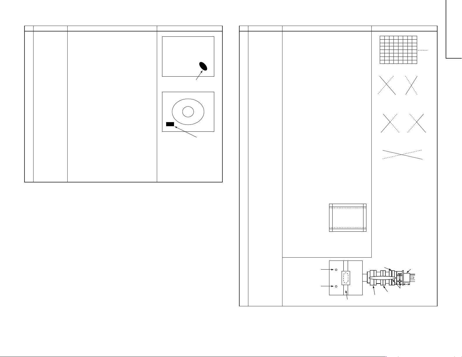
CONVERGENCE ADJUSTMENT
Adjustment Condition / Procedure Waveform or others
(1)Receive E-2CH (the Crosshatch pattern).
(2)Using the remote controller, call NORMAL
mode.
Static Convergence Adjustment
1. Overlap blue and red with the open-/closing
angle and rotation of the 4 pole magnet.
2. Overlap green on blue and red with the open/closing angle and rotation of the 6 pole magnet.
Dynamic Convergence Adjustment
1. Fix the wedges in a position so that the deflection yoke neck is at the center of top bottom and left right. (Straight line and without
any blur horizontal / vertical line)
2. Adjust the Red, Blue, upper and lower of the
center y axis on the screen by using the Volume (YH,YHC) at the deflection yoke.
Refer to Fig. 6-2 and Fig. 6-3
3. If the Horizontal Red. Blue (XV) on the screen
center X axis is shifted, correct the Red. Blue
(XV) by adjusting the balance coil on the deflection yoke.
Refer to Fig.6-4.
4. After confirm that there is no problems on the
entire screen, bond wedge on CRT and glass
tape on it. Fastening the screws of DY and
magnet unit (purity, 4-pole and 6 pole), then
coat the lacquer paint on DY fastening screw
and magnet unit fastening screw.
Note:In case of poor convergence adjustment
on the top and bottom of the screen, adjust DY by swing rightward and leftward.
Refer to Fig.6-1
Y axis
B
R
Fig. 6-2
Adjust by YHC
B
R
Fig. 6-3
Adjust by YH
Fig. 6-4
Adjust by Balance Coil
29WF50
X axis
RB
RB
B
Adjust by swing DY
Note:For CRT drawing, please refer to following
page.
YHC
YH
10-1 10-2
Fig. 6-1
Balance Coil
6-Pole Magnet
Purity Magnet
Lacquer
4-Pole Magnet
CRT Neck
25 ± 0.5mm
Page 9

11
No.
Adjustment point
1 DYNAMIC
FOCUS
ADJUSTMENT
L1680
(in the power
unit)
2
FOCUS
ADJUSTMENT
FBT FOCUS
VR
FOCUS ADJUSTMENT
Adjustment Condition / Procedure Waveform or others
1. Receive E-5CH (Monoscope pattern).
2. With the remote controller, make it normal.
3. Connect the oscilloscope to the pin (8) of
T1680.
4. Turning L1680, adjust the amplitude of the
horizontal frequency waveform to 1,000Vp-p.
1,000 – 50Vp-p
V-FREQ
1. ReceiveE-5CH (Monoscope pattern).
2. With the remote controller, make it normal.
3. Adjust the focus VR-1(F1) to make the horizontal line around "575" on the bottom left of
the screen as fine as possible.
4. Adjust the focus VR-2(F2) to make the vertical line around "575" on the bottom left of the
screen as fine as possible.
5. Repeat item 3 once again to adjust the focus.
Approx. 1,000Vp-p
No.
Adjustment point
2 WHITE
BALANCE
BACKGROUND
(CUT OFF
BKGD)
2
I
C BUS
ADJUSTMENT
(AV SIGNAL)
CUT OFF, BKGD, SUB-CONT ADJUSTMENT
Adjustment Condition / Procedure Waveform or others
1. Receive E-5CH (Monoscope pattern).
2. Select P-NORM with the remote controller.
3. Connect the beam ammeter between TP1601
and TP1602.
4. Coarsely adjust the beam current to approx.
1.8mA with R1633 (Sub-Contrast VR)
5. Receive the window pattern signal with AV input.
(PAL burst is generated with the signal generator.)
6. With the data of G-drive and B-drive, adjust
the colour temperature 12,300°K of the white
peak to white.
7. Adjust the right dark area of the window to
12,300°K with R-cut off, G-cut off and B-cut
off.
8. Readjust the colour temperature at the white
peak.
9. Check 12,300°K at the low white.
Note : Apply this adjustment after aging with the
beam current 1,600 ± 50µA or more for
30 min or more.
(On the white or green monocolour
screen.)
* The colour temperature is based on the ship-
ment initial setting table.
Note1:
R CUT OFF UP "1" KEY
DOWN "4" KEY
G CUT OFFUP "2" KEY
DOWN "5" KEY
B CUT OFF UP "3" KEY
DOWN "6" KEY
Data up/down is possible with the
above comparison.
* 12,300°K X : 0.272
Y : 0.275
(With Monolta colour thermometer
CA-100)
Note2:
G-DRIVE UP "7" KEY
DOWN "
B-DRIVE UP "8" KEY
DOWN "0" KEY
Data up/down is possible with the
above comparison.
" KEY
No.
Adjustment point
CRT CUTOFF
1
(CUT OFF
BKGD)
SERVICE
MODE I
DATA
ADJUSTMENT
CUT OFF, BKGD, SUB-CONT ADJUSTMENT
Adjustment Condition / Procedure Waveform or others
2
C BUS
1. Receive E-5CH (Monoscope pattern).
2. Select P-NORM with the remote controller.
3. Turn on the service SW, and select the CUT
OFF BKGD mode.
4. Select the screen VR 0/10.
5. Press "-/--" key of the remote controller to select the horizontal centering mode.
6. Turn the screen VR clockwise, and adjust the
first lightinghorizontal centering raster to slightly
light.
7. Adjust the CUT OFF data of two other colours,
and coarsely adjust the horizontal centering
to become white. (Note 1)
8. Turn the screen VR in the opposite direction
to the point where the horizontal centering
raster goes out.
Note 1: Apply the adjustment after aging with
the beam current 1,600 ± 50µA or
more for 30 min or more.
9. Press "-/--" key of the remote controller to select the normal mode.
11-1 11-2
* Before doing the adjustment,
make sure the R/G/B-cut and B/
G-Drive is at initial values.
On the monocolour screen of white
or green.
3 WHITE
BALANCE
BACKGROUND
(CUT OFF DVD
BKGD)
2
C BUS
I
ADJUSTMENT
(DVD SIGNAL)
4 MAX BEAM
R1759
1. Receive the window pattern with DVD signal
(component signal).
2. Apply the adjustment in the same manner as
2 (5) and the subsequence above. (12,300°K)
(G-DRIVE, B-DRIVE, R-CUT OFF, G-CUT
OFF, B-CUT OFF)
Apply the adjustment after the end of 2.
1. Receive E-5CH (Monoscope pattern) with
standard mode.
2. Make the image normal with the remote controller. (AV mode: DYNAMIC)
3. Connect the beam ammeter between TP1601
and TP1602.
Ammeter full scale-3mA range
Connect the - side of the ammeter to TP1602.
Connect the + side of the ammeter to TP1601.
4. Adjust the beam current to 1.8mA ± 20µA with
R1759 (sub-contrast VR).
Note: Apply the adjustment after aging with the
beam current 1,600 ± 50µA or more for 30
min or more.
(On the white or green monocolour screen.)
Note : Use the window pattern of
the signal generator for
adjustment.
(PAL, colour burst is generated with
signal generator)
29WF50
Page 10

12
No.
Adjustment point
5 SUB-
CONTRAST
(SUB-CONT)
2
C BUS
I
ADJUSTMENT
(AV SIGNAL)
6 SUB-
CONTRAST
(SUB-CONT
DVD)
I2C bus
adjustment
(DVD Signal)
7 SUB-
BRIGHTNESS
ADJUSMENT
(SUB BRI)
2
(I
C BUS
CONTROL)
(AV SIGNAL)
SUB-
8
BRIGHTNESS
(SUB BRI
DVD)
2
C bus
I
adjustment
(DVD SIGNAL)
CUT OFF, BKGD, SUB-CONT ADJUSTMENT
Adjustment Condition / Procedure Waveform or others
1. Receive the window pattern signal with AV input.
2. Make the image normal with the remote controller. (AV mode: DYNAMIC)
3. Select the SUB-CONTRAST adjustment mode
with the remote controller, and adjust 50%
white to 165 ± 10 cd.
1. Select the DVD mode.
2. Receive the signal of the DVD signal generator. (Component signal) (Window pattern)
3. Make the picture normal with the remote controller. (AV mode: DYNAMIC)
4. Select the SUB-CONTRAST adjustment mode
(DVD) with the remote controller, and adjust
50% white to 165 ± 10 cd.
1. Receive the window pattern signal with AV input.
2. Make the image normal with the remote controller. (AV mode: DYNAMIC)
3. Select the sub-bright adjustment mode with the
remote controller, and adjust the right dark
white area of the window pattern to 5.5 ± 0.5
cd.
1. Select the DVD mode.
2. Receive the signal of the DVD signal generator. (Component signal) (Window pattern)
3. Make the picture normal with the remote controller. (AV mode: DYNAMIC)
4. Select the SUB-BRIGHT adjustment mode
(DVD) with the remote controller, and adjust
the right dark white area of window pattern to
5.5 ± 0.5 cd of window pattern.
Note:
Use "Y" of Minolta colour
analyzer CA-100 in adjustment.
Note:
Use the PAL window pattern of
the signal generator for adjustment.
(PAL and colour burst are provided.)
Note:
Window pattern
50%white for SUB-CONT
* When E-2CH (Crosshatch pat-
tern) or equivalent signal is
receiived.
1. Make the image normal with the
remote controller.
2. Adjust the 3rd (1 thru 5 from the
left) black of the window pattern
to sink.
CUT OFF POINT
Dark white for
SUB-BRIGHT
HORIZONTAL, VERTICAL, DEFLECTION LOOP AND ADJUSTMENT
No.
Adjustment point
1 V-AMP 50
V-LINE 50
V-S CORR50
V-CENT50
Adjustment Condition / Procedure Waveform or others
Adjust the overscan to 8.5%. (E-5)
Adjust the linearity to the best.
Already preset. (Adjust this unless the linearity is
achieved.)
The receiving channel in ( ) are the
following signals.
(E-2) : Crosshatch (50Hz)
(E-5) : Monoscope (50Hz)
Align the center of the screen to the geometric
center of CRT. (E-5)
H-CENT50
Align the center of the screen to the geometric
center of CRT. (E-5)
H-SIZE50
E/W-P AR50
Adjust the overscan to 8.5%. (E-5)
Adjust the 2nd vertical line from the left end of
crosshatch pattern so that the middle 4 blocks
EW-COR50
are straight. (E-2) (refer to Fig.7-1)
Adjust the 2nd vertical line from the left end of
Fig.7-1
crosshatch pattern so that the top are straight.(E-
2) (Refer to Fig.7-2)
TRAPE50
Adjust the 2nd vertical line from the left end of
crosshatch pattern so that the D1 (centre area of
the second vertical line-edge of screen) and D2
(top area of the second vertical line-edge of
screen) are same. (Refer to Fig.7-3)
V-ENT
H-ENT
OTHER
Already preset.
Already preset.
On the items of V-AMP60, V-LINE60, V-S
CORR60, V-CENT60, H-CENT60, H-SIZE60,
Fig.7-2
D2
D1
EW-P AR60, EW-COR60 andTRAPE60, the compensation data is automatically input if the 50Hz
mode adjustment is done.
2
C BUS
I
ADJUSTMENT
Attention:
Don't change 50 Hz mode data after adjust
60 Hz mode data. Because 60 Hz mode
data follow 50 Hz mode data automatically.
However, if it is largely deviated
when it is checked in the 60Hz
mode, readjust it in the 60Hz mode.
Fig.7-3
PAL CHROMA ADJUSTMENT
No.
Adjustment point
1 SUB COLOUR
2
C BUS
(I
CONTROL)
(RF signal)
Adjustment Condition / Procedure Waveform or others
1. Receive the E-10CH (PAL Colour Bar).
2. Make the picture normal with the remote con-
75%W
Y
100%W
troller.
3. Connect the oscilloscope to TP802 (pin (4) of
KY) (Use Probe10:1)
Range : 2V/Div
Sweep time : 20µ sec/Div
Cy G
4. Set the "SUB-COL" adjustment mode with the
remote controller, and vary the sub colour data
to make 75% W of the PAL colour bar and RED
Fig. 8
at the same level for adjustment shown in Fig.
8.
Mg
R
B
29WF50
12-1 12-2
Page 11

No.
Adjustment point
1 SUB-TINT
(SUB TINT)
2
C BUS
(I
CONTROL)
(AV SIGNAL)
NTSC CHROMA ADJUSTMENT
Adjustment Condition / Procedure Waveform or others
1. Select the sub-tint adjustment mode (automatic
Y cut) to receive the NTSC colour bar signal
with AV input.
2. Connect the oscilloscope to TP801.
Range : 50mV/Div (AC)
(Use Probe 10:1)
Sweep time : 10µsec/Div
3. Vary the sub tint data to adjust the waveform
to be gained as shown in Fig 9.
TP801………………(KY) 6 pin
A
B
C
W Y Cy G Mg R B Blk
A=B=C
Fig.9
FUNCTION OPERATION CHECKING (1) (VIDEO & AUDIO)
No.
Adjustment point
CONTRAST
1
Key
2 COLOUR Key 1. Receive the Colour Bar signal.
Adjustment Condition / Procedure Waveform or others
1. Receive the Monoscope Pattern signal.
2. Press to Menu mode, then select Picture Mode
and set to select CONTRAST .
3. Press Volume Up/Down key to check whether
the CONTRAST effect is OK or not.
2. Press to Menu mode, then select Picture Mode
and set to select COLOUR.
3. Press Volume Up/Down key to check whether
the COLOUR effect is OK or not.
13
No.
Adjustment point
1 SECAM
BLACK LEVEL
R-Y/B-Y
2
C BUS
I
ADJUSTMENT
SECAM CHROMA ADJUSTMENT
Adjustment Condition / Procedure Waveform or others
1. Receive "SECAM colour bar" signal.
2. Select SECAM black level adjustment R-Y
mode.
3. Connect the oscilloscope to pin(20) of
IC800(TP802/R out).
• Range : 10mV/Div.
•Sweep time : 20 µsec/Div.
(Use Probe 10:1)
4. Vary R-Y data to minimize the offset between
the non-signal line and signal line as shown in
Fig.10-1(b)
5. Select SECAM black level adjustment B-Y
mode.
6. Reconnect the oscilloscope to TP801...(KY)
6pin
• Range : 10mV/Div.
• Sweep time : 20 µsec/Div.
(Use Probe 10:1)
7. Vary B-Y data to minimize the offset between
the non-signal line and signal line as shown in
Fig.10-2(b)
Fig. 10-1(a)
Fig. 10-1(b)
Fig. 10-2(a)
OFF SET
OFF SET
3 BRIGHTNESS
Key
4 TINT Key 1. Receive the NTSC Colour Bar signal thru AV
5 SHARPNESS
Key
6 NORMAL Key 1. Once in PICTURE Mode, and the NORMAL
7 WHITE TEMP 1. Receive the Monoscope Pattern signal.
1. Receive the Monoscope Pattern signal.
2. Press to Menu mode, then select Picture Mode
and set to select BRIGHTNESS.
3. Press Volume Up/Down key to check whether
the BRIGHTNESS effect is OK or not.
input.
2. Press to Menu mode, then select Picture Mode
and set to select TINT.
3. Press Volume Up/Down key to check TINT , UP
for GREEN direction and DOWN for RED direction whether is OK or not.
1. Receive the Monoscope Pattern signal.
2. Press to Menu mode, then select Picture Mode
and set to select SHARPNESS.
3. Press Volume Up/Down key to check whether
the SHARPNESS effect is OK or not.
key is pressed, all the settings will be present
to normal setting.
(Normal setting value for every mode, refer on
page 8.)
2. Set FUNCTION to select WHITE TEMP .
3. Press Volume Up/Down key to check WHITE
TEMP Option, STANDARD: NORMAL SETTING, WARM for more REDDISH direction
changing, COOL for more BLUISH direction
changing.
Note:
If nothing is display mean contrast,
colour, brightness, tint, sharpness
are all in normal setting.
29WF50
Fig. 10-2(b)
13-1 13-2
Page 12

FUNCTION OPERATION CHECKING (2) (VIDEO & AUDIO)
No.
Adjustment point
8 COLOUR
SYSTEM
Adjustment Condition / Procedure Waveform or others
1. Receive the "PAL COLOUR BAR" signal,
press the COLOUR SYSTEM key to select
modes except PAL, check the COLOUR is not
working properly. Then, select the "P AL" mode.
Check again its colour so that it is working
properly.
2. Receive "SECAM COLOUR BAR" signal,
press COLOUR SYSTEM key to select modes
except SECAM, check the COLOUR is not
working properly. Then, select the "SECAM"
mode. Check again its colour so that it is working properly.
3. Receive “NTSC 3.58” signal, press COLOUR
SYSTEM key to select modes except
NTSC3.58, check the COLOUR is not working properly. Then, select the “NTSC 3.58”
mode. Check again its colour so that it is working properly.
4. Receive “NTSC 4.43/3.58 COLOUR BAR” signal thru AV, press COLOUR SYSTEM key to
select modes except N4.43, check the COLOUR is not working properly. Then, select the
“NTSC 4.43” mode. Check again its colour so
that it is working properly.
PROTECTOR OPERATION CHECK
No.
Checking Item
H.V Protector 1. Receive E-5CH (Monoscope pattern).
1
Other
2
protectors
Adjustment Condition / Procedure Waveform or others
2. Connect the bias box to the cathode side
(R1662 side) of D1621.
3. Set the voltage of the bias box at 15V, and
verify that the protector does not operate.
4. Set the voltage of the bias box at 24V, and
verify that the protector does operate.
Correspondence for short circiut of smoothening
electrolysis of +B line and so on.
To check the operation of the protector and so
on, take care for the breakage, deterioration and
so on of each element.
29WF50
Reference Approx. 17.7 V as ordinary.
14
SOUND
9
SYSTEM
10
HEADPHONE
OUTPUT
CHECKING
1. Receive “PAL-D/K” signal, press the “SOUND
SYSTEM” to select B/G, I. Check the sound
output is not working properly. Select D/K and
check the sound output to make sure it is working properly.
2. Receive “PAL-I” signal, press the “SOUND
SYSTEM” to select B/G, D/K. Check the sound
output is not working properly. Select I and
check the sound output to make sure it is working properly.
3. Receive “PAL-B/G” signal, press the “SOUND
SYSTEM” to select I, D/K. Check the sound
output is not working properly. Select B/G and
check the sound output to make sure it is working properly.
1. Receive the PAL Colour Bar signal with sound
400 Hz, 100% modulation (± 50kHz Dev)
2. Maximum volume, and check the headphone
output with 400 Hz sound and no sound out
from speaker.
(Ref: Output Level of Headphone is as Follow-
ing:)
SUB-VOL Adj. H/P Output (Open)
63 1.0 Vp-p
40 500 mVp-p
14-1 14-2
Page 13

29WF50
CHASSIS LAYOUT
H
G
F
E
D
C
B
A
654321
20
Page 14

BLOCK DIAGRAM-1
H
CRT Unit
G
F
29WF50
E
D
C
B
A
654321
21
Page 15

29WF50
BLOCK DIAGRAM-2
PWB-A MAIN Unit -1/2
H
G
F
29WF50
E
D
C
B
A
22
87109654321
23
1716 19181514131211
Page 16

29WF50
BLOCK DIAGRAM-3
PWB-A MAIN Unit -2/2
H
G
F
29WF50
E
D
C
B
A
24
87109654321
25
1716 19181514131211
Page 17

29WF50
BLOCK DIAGRAM-4
29WF50
H
POWER Unit
G
F
E
D
C
B
A
26
87109654321
1716 19181514131211
27
Page 18

29WF50
BLOCK DIAGRAM-5
H
G
F
NICAM Unit
E
D
C
B
A
654321
28
Page 19

BLOCK DIAGRAM-6
H
G
F
29WF50
OPERATION Unit
E
D
C
B
A
654321
29
Page 20

29WF50
WAVEFORMS
30
Page 21

29WF50
SCHEMATIC DIAGRAM: MAIN-1 Unit
H
G
F
29WF50
E
D
C
B
A
32
87109654321
33
1716 19181514131211
Page 22

29WF50
SCHEMATIC DIAGRAM: MAIN-2 Unit
H
G
F
29WF50
E
D
C
B
A
34
87109654321
35
1716 19181514131211
Page 23

29WF50
SCHEMATIC DIAGRAM: POWER Unit
H
G
F
29WF50
E
D
C
B
A
36
87109654321
37
1716 19181514131211
Page 24

29WF50
SCHEMATIC DIAGRAM: CRT Unit
H
G
F
E
D
C
B
A
654321
38
Page 25

SCHEMATIC DIAGRAM: NICAM Unit
H
G
F
29WF50
E
D
C
B
A
654321
39
Page 26

29WF50
SCHEMATIC DIAGRAM: OPERATION Unit
H
G
F
E
D
C
B
A
654321
40
 Loading...