

Page 1

Manual
Page 2

TABLE OF CONTENTS
1. General 3
2. Specific ations 3
2.1 Overview SHP550 V2 3
2.2 Overview SHP650 V2 3
2.3 Mains Voltage and Protections 4
2.4 Safety Certifications 4
3. Package Contents 4
4. Cable Configuration 5
4.1 Connectors 5
4.2 Cable Length 5
5. Installation 6
5.1 Installing the Power Supply into a PC Case 6
5.2 Connecting Mainboard and Graphics Card(s) 6
5.3 Connecting Optical Drives and Other Peripheral Devices 6
5.4 Checking All Connections 7
6. Troubleshooting 7
SHP V2
Page 3
3
Dear Customer,
Thank you for your purchase of this high-quality SHARKOON product. To ensure a long service life, and full
functionality of the product, we recommend that you read this manual thoroughly.
SHARKOON Technologies
www.sharkoon.com
1. General
Power
CPU
Warrant y
PCIe Connectors
Fan
Efficiency
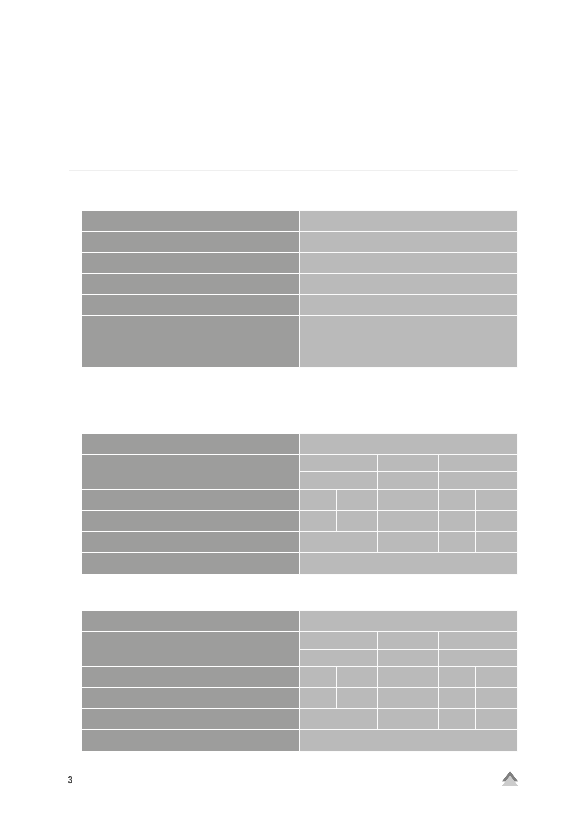
2. Specifications
2.1 Overview SHP550 V2
Model No.
Input (AC)
Output (DC)
550 or 650 Watt
Compatible with the Latest Intel and AMD CPUs
2 Years
2x 6 +2-Pin PCIe Connector
120 mm Fan
20% Load: Min. 82%
50% Load: Min. 85%
100% Load: Min. 82%
SHP550 V2
Input Voltage Current Frequency
200-24 0 VAC 4 A 47-63 Hz
+3.3 V +5 V +12 V -12 V +5 Vsb
Max. Output Current
Max. Combined Power
Total Power
2.2 Overview SHP650 V2
Model No.
Input (AC)
Output (DC)
Max. Output Current
Max. Combined Power
Total Power
18 A 18 A 42 A 0.3 A 2.5 A
110 W 504 W 3.6 W 12.5 W
550 Watt
SHP650 V2
Input Voltage Current Frequency
200-24 0 VAC 5 A 47-63 Hz
+3.3 V +5 V +12 V -12 V +5 Vsb
20 A 20 A 50 A 0.3 A 2.5 A
120 W 600 W 3.6 W 12.5 W
650 Watt
SHP V2
Page 4

4
2.3 Mains Voltage and Protections
This power supply works with 200-240 V. It is available with the following protective measures:
1. Over Power Protection (OPP)
If a voltage rail draws in more electricity to the power supply than the specifications allow, the power supply
will switch off.
2. Over Voltage Protection (OVP)
This function protects against excessive voltage, preventing damage to the PC by switching off the power
supply during a surge.
3. Shor t Circuit Protection (SCP)
Should a short circuit occur with your PC, the SCP function switches off the power supply and protects
the electronics from damage.
4. Under Voltage Protection (UVP)
Should the power supply fall below a fixed number for the minimum voltage it will switch off automatically.
2.4 Safety Certifications
Out power supply is tested and complies with CE and CB safety certifications.
3. Package Contents
A
B
D
A
SHP550 V2/SHP550 V2
B
Mounting screws
C
Power cord
D
Manual
Note:
If you are missing any of the items listed above, please contact our customer service immediately:
support@ sharkoon.com (Europe)
support@sharkoon.com.tw (International)
C
SHP V2
Page 5

450 mm
450 mm
450 mm
450 mm
150 mm
150 mm
150 mm
450 mm 150 mm
450 mm 150 mm
150 mm
5
4. Cable Configuration
4.1 Connectors
1x 20+4-Pin Mainboard Connector
4x SATA Connectors
4.2 Cable Length
1x 20+4-Pin
Mainboard
Connector
1x 4+4-Pin
CPU
Connector
1x 4+4-Pin CPU Connector
1x Floppy Connector
2x 6 +2-Pin
PCIe Connectors
3x 4-Pin
IDE Connectors
2x 6 +2-Pin PCIe Connectors
3x 4-Pin IDE Connectors
1x Floppy
Connector
4x SATA
Connectors
SHP V2
Page 6

6
5. Installation
If installing into an empty PC case please continue to section 5.1. If a power supply is already installed, remove
it first from the case. To do so, proceed as follows:
1. Turn off your PC. Disconnect the power cord from the wall outlet and your power supply.
2. Open the PC case. For additional information, refer to the PC case’s manual.
3. Disconnect all cables between the power supply and the other PC components (e.g. mainboard, HDDs,
drives, fans, etc.).
4. Remove the mounting screws connecting the power supply to the PC case and then carefully remove the
power supply from the case.
5.1 Installing a Power Supply into a PC Case
1. Insert the power supply into the PC case and place it against the power supply bracket on the rear panel.
For additional information, refer to the PC case’s manual.
2. At tach the power supply from the outside of the case using the provided screws. Ensure that the fan and air
vents of the built-in power supply are not covered.
5.2 Connect the Mainboard and Graphics Card (s)
1. Plug the 20+4-pin mainboard connector (Fig. 1) into the respective port on the mainboard.
2. If your mainboard also features either a 4-pin or 4+4-pin CPU connector, connect the plug with the
mainboard port (Fig. 2).
Note:
The power connection of the mainboard depends on the vendor and may vary. For detailed information on how
to establish the connector, please refer to your mainboard’s manual.
3. If your PCIe graphics card requires an additional power supply, connected the 6-pin or 6+2-pin PCIe
connector to ensure the graphics card receives a stable power supply.
5.3 Connecting Optical Drives and Other Peripheral Devices
1. Connect the 4-pin IDE connector (Fig. 4), SATA connector (Fig. 5) and the 4-pin Floppy connector (Fig. 6)
with the corresponding peripheral devices.
Note:
For additional information, refer to the respective manuals of your drives and peripheral devices.
Fig. 1:
20+4-Pin Mainboard Connector
Fig. 2:
4+ 4-Pin CPU Connector
Fig. 3:
6+2-Pin P CIe Connector
Fig. 4:
4-Pin IDE Connector
Fig. 5:
SATA Connector
Fig. 6:
Floppy Connector
SHP V2
Page 7

7
5.4 Checking All Connections
Ensure that all devices are properly connected. Close the PC case. Connect the power cord with the power
supply and wall outlet. Turn the power supply on. This completes the installation of the power supply.
Note:
All connectors are designed to avoid misconnection. If the connectors are unable to connect to the mainboard, drives or peripheral devices, please check if both connectors are attached in the correct orientation.
Do not force to plug the connectors within the incorrect orientation, nor modify any of the components, as
this will damage the power supply and other hardware. SHARKOON warranty does not cover damage cause
by incorrect handling.
6. Troubleshooting
If the power supply does not work properly, please check the following:
1. Is the power cord correctly inserted into a wall outlet and the power inlet of the power supply?
2. Ensure that the on/off switch is in the “I” position.
3. Check if the 20 +4-pin mainboard connector and the 4+4-pin CPU connector are correctly at tached to the
mainboard.
4. Check if the cable is securely connected to the port of the peripheral devices.
5. Unplug the power cord from the wall outlet and let the power supply rest for about 10 minutes.
This will trigger a reset of the protection circuitry.
If the system still does not star t, please contact support@sharkoon.com.
SHP V2
Page 8

8
Legal Disclaimer:
For potential loss of data, especially due to inappropriate handling, SHARKOON assumes no liability. All named
products and descriptions are trademarks and/or registered trademarks of the respective manufacturers and
are accepted as protected. As a continuing policy of product improvement at SHARKOON, the design and
specifications are subject to change without prior notice. National product specifications may vary. The legal
rights of the enclosed software belong to the respective owner. Please observe the license terms of the manufacturer before using the software. All rights reserved especially (also in extracts) for translation, reprinting,
reproduction by copying or other technical means. Infringements will lead to compensation.
Disposal of your old product:
Your device has been designed and manufactured using high quality materials and components that can be
recycled and reused.
When this crossed-out wheeled bin symbol is attached to a product, it means the product is covered by
the European Directive 2012 /19/EU. Please be informed about the local separate collection system for
electrical and electronic products. Please act according to your local rules and do not dispose of your
old products with your normal household waste. The correct disposal of your old product will help prevent
potential negative consequences to the environment and human health.
SHARKOON Technologies GmbH
Siemensstraße 38
3544 0 Linden
Germany
© SHARKOON Technologies 2016
info@sharkoon.com
www.sharkoon.com
SHP V2
 Loading...