

Page 1
Flight manual UL aircraft
FLIGHT MANUAL
UL airplane
SHARK.AERO s.r.o
SHARK.AERO CZ s.r.o.
Version: AFM Shark-EN 60_2017-05-17_final
created from Czech original version :
AFM_Shark-CZ_60_2017-04-22_certifikat.doc
Page 2

Page 3
Flight manual UL aircraft
Airplane Type / version: SHARK UL
Serial number:
Registration:
Date of issue:
LAA - Approval number and date:
ULL - 05 / 2013
1.3. 2013 / 20.12. 2016
Manufacturer – stamp and signature :
The airplane must be operated according to informations and
limitations presented in this handbook.
This handbook must be available to pilot at any time of the
flight.
Page 4

Page 5
Flight manual UL aircraft
LIST OF THE REVISIONS AND THE EPAIRS
Ordinal
No.
Number of
document bulletin
It concerns to pages No.
Date of
issue
Signature
1/13
2-1,2-2,2-6,2-9,
3-1 to 3-3, 3-6 to 3-8
4-1 to 4-11
5-1 to 5-5
6-2
7-8 to 7-10
appendix 3-3
format editing
5.3.2013
V.Pekár
2/13
2-6,2-7,6-1 to 6-7
15.3.2013
V.Pekár
3/13
2-6, 5-1,5-2,6-4,6-5,6-6
4.4.2013
V.Pekár
4/15
2-4, 2-6, 7-10, 7-18, 8-6
28.4.2015
J. Skočej
5/16
57-00
1-2,2-3,2-4,2-6, 3-6, 4-3,
4-7, 4-11,4-12, 5-2 to 5-6,
6-6, 7-1, 7-10, 7-11, 7-12,
7-14, 7-15, 7-18 to 7-27,
8-6
19.5.2016
V.Pekár
6/16
57-02
4-13
17.7.2016
V.Pekár
7/16
57-03
3-6 to 3-9, 5-2, 5-3, 7-1,
7-7, 7-14,7-19 to 7-29
22.8.2016
V.Pekár
8/16
57-04
4-15, 6-7 to 6-9
22.12.2016
V.Pekár
9/17
57-05
1-2, 2-1, 2-8, 2-9, 4-15,
6-2, 6-4, 6-5
1.2.2017
V.Pekár
10/17
57-06
Rewritten as a part of the
LAA type certification
requirements
1.4.2017
J.Dostál
Page 6

Flight manual UL aircraft
Page 7

Flight manual UL aircraft
Content
1. General ........................................................................ 1-1
1.1. Introduction .................................................................. 1-1
1.2. Certification bases ....................................................... 1-1
1.3. Warnings, cautions and notes ..................................... 1-1
1.4. Airplane basic description ............................................ 1-2
1.5. Three view drawing ...................................................... 1-3
2. Limitations .................................................................... 2-1
2.1. Airspeed ....................................................................... 2-1
2.2. Airspeed indicator markings ....................................... 2-1
2.3. analog airspeed indicator markings ............................. 2-2
2.4. Engine .......................................................................... 2-3
2.5. Engine instrument marking .......................................... 2-4
2.6. Weight limits ................................................................ 2-5
2.7. Center of gravity (CG) .................................................. 2-6
2.8. Approved maneuvers ................................................... 2-6
2.9. Maneuvering load factor G .......................................... 2-6
2.10. Flight crew ................................................................... 2-6
2.11. Kind of operation .......................................................... 2-7
2.12. Fuel .............................................................................. 2-7
2.12.1. Approved fuel types ..................................................... 2-7
2.12.2. Fuel tanks capacity ...................................................... 2-7
2.13. Other limitations ........................................................... 2-8
2.14. Placards ....................................................................... 2-9
3. Emergency procedures................................................ 3-1
3.1. Engine failure and emergency landing ........................ 3-1
3.1.1. Engine failure during take-off run ................................ 3-1
3.1.2. Engine failure during take-off ....................................... 3-1
3.1.3. In-flight engine failure .................................................. 3-2
3.1.4. Carburettor icing .......................................................... 3-2
3.2. In-flight engine restart .................................................. 3-2
3.3. Fire ............................................................................... 3-3
3.3.1. Engine fire on the ground ............................................ 3-3
3.3.2. Engine fire during take-off............................................ 3-3
3.3.3. Engine fire in flight ....................................................... 3-3
3.3.4. Cockpit / electrical fire .................................................. 3-4
3.4. Gliding .......................................................................... 3-4
3.5. Precautionary Landing ................................................. 3-4
3.6. Blown-Out Tire Landing ............................................... 3-4
3.7. Landing with Damaged Landing Gear ......................... 3-5
3.8. Landing gear retraction malfunction ............................ 3-5
3.9. Landing gear opening malfunction .............................. 3-5
3.10. Vibrations from engine or other engine problem ........ 3-6
Page 8

Flight manual UL aircraft
3.11. Inadvertent icing encounter ......................................... 3-6
3.12. Extreme turbulence encounter .................................... 3-6
3.13. Electrical system malfunctions .................................... 3-7
3.14. Inadvertent Stall and spin recovery ............................. 3-8
3.14.1. Stall recovery ............................................................... 3-8
3.14.2. Spin recovery ............................................................... 3-8
3.15. USe of Rescue system ................................................ 3-9
4. Normal procedures ...................................................... 4-1
4.1. Pre-flight inspection ..................................................... 4-1
4.1.1. Cockpit ......................................................................... 4-1
4.1.2. Wing ............................................................................. 4-2
4.1.3. Landing gear ................................................................ 4-2
4.1.4. Powerplant ................................................................... 4-2
4.1.5. Control cables .............................................................. 4-3
4.1.6. Tail unit and fuselage .................................................. 4-3
4.1.7. Turning on of electric devices ...................................... 4-3
4.2. Engine starting ............................................................. 4-3
4.2.1. Engine warm-up and test ............................................. 4-4
4.3. Before taxiing ............................................................... 4-4
4.4. Taxiing ......................................................................... 4-6
4.5. Check on holding line .................................................. 4-6
4.6. normal take off ............................................................. 4-7
4.7. Climb ............................................................................ 4-7
4.8. Cruise .......................................................................... 4-8
4.9. Approach ..................................................................... 4-8
4.9.1. Descent ........................................................................ 4-8
4.10. Downwind .................................................................... 4-9
4.11. Normal landing ............................................................ 4-9
4.11.1. On Base Leg ................................................................ 4-9
4.11.2. On Final ....................................................................... 4-9
4.11.3. Landing ........................................................................ 4-9
4.11.4. After landing............................................................... 4-10
4.11.5. Engine shut down ...................................................... 4-10
4.11.6. Post-Flight Check ...................................................... 4-10
4.12. Short field take-off and landing procedures .............. 4-10
4.13. Balked landing procedures ........................................ 4-10
4.14. Fuel SYSTEM use ..................................................... 4-11
4.15. REPEATED TAKE OFF ............................................. 4-11
4.16. High speed flights ...................................................... 4-12
4.16.1. Turbulences ............................................................... 4-12
4.16.2. Maneuvering .............................................................. 4-12
4.16.3. Landing gear opening ................................................ 4-12
4.16.4. Propeller, engine RPM .............................................. 4-13
Page 9

Flight manual UL aircraft
4.16.5. Flaps .......................................................................... 4-13
4.16.6. Landing gear retraction .............................................. 4-13
4.16.7. Flutter, high altitude flights ......................................... 4-13
5. Performance ................................................................ 5-1
5.1. Airspeed indicator system calibration .......................... 5-1
5.2. Stall speed ................................................................... 5-2
5.3. TAKE-OFF Distance .................................................... 5-2
5.3.1. In flight adjustable prop. NEUFORM TXR2-V-70 ....... 5-2
5.3.2. In flight adjustable prop. Woodcomp SR3000/2WN .... 5-3
5.3.3. On ground adjustable prop. DUC SWIRL 1680 ........... 5-3
5.4. Landing distance .......................................................... 5-4
5.5. Rate of climb ................................................................ 5-4
5.6. Cruise, endurance, range ............................................ 5-5
6. Airplane empty weight and COG determination .......... 6-1
6.1. Weight and center of gravity determination for flight .. 6-3
7. Technical Description of the airplane .......................... 7-1
7.1. AIRFRAME .................................................................. 7-2
7.1.1. Fuselage ...................................................................... 7-2
7.1.2. Cockpit canopy ............................................................ 7-2
7.1.3. Engine cowlings ........................................................... 7-2
7.1.4. Wing ............................................................................. 7-3
7.1.5. Ailerons ........................................................................ 7-3
7.1.6. Flaps ............................................................................ 7-3
7.1.7. Horizontal stabilizer ..................................................... 7-3
7.1.8. Elevator ........................................................................ 7-3
7.1.9. Rudder ......................................................................... 7-3
7.1.10. Airplane exterior surface painting ................................ 7-4
7.2. Landing gear ................................................................ 7-4
7.2.1. Front undercarriage ..................................................... 7-4
7.2.2. Main undercarriage ...................................................... 7-5
7.2.3. Undercarriage retraction and extension ...................... 7-6
7.3. CONTROL SYSTEMS ................................................. 7-8
7.3.1. Elevator control ............................................................ 7-8
7.3.2. Aileron control .............................................................. 7-8
7.3.3. Rudder control ............................................................. 7-9
7.3.4. Flaps ............................................................................ 7-9
7.3.5. Elevator trim tab control ............................................... 7-9
7.4. ELECTRIC SYSTEM ................................................. 7-10
7.5. Fuel system ............................................................... 7-10
7.6. COCKPIT - interior and instruments .......................... 7-12
7.7. POWER UNIT .............................................................. 7-16
7.7.1. Technical data ........................................................... 7-17
7.8. PROPELLER ............................................................. 7-18
Page 10

Flight manual UL aircraft
7.8.1. DUC SWIRL 3 blade, on the ground adjustable
propeller, diameter 1680 mm ..................................... 7-18
7.8.2. Woodcomp SR 3000 2W two blade in flight electrically
adjustable propeller ................................................... 7-19
7.8.3. Woodcomp KW 20W - two blade hydraulically in flight
adjustable .................................................................. 7-20
7.8.4. Neuform TXR2-V-70 .................................................. 7-21
7.9. Rescue system .......................................................... 7-22
7.9.1. Description of rescue system Stratos/Junkers Magnum
501 ............................................................................. 7-22
7.9.2. The activation mechanism ......................................... 7-23
7.9.3. Rescue system installation ........................................ 7-24
7.10. Towing system ........................................................... 7-25
7.11. Position lights............................................................. 7-26
7.12. Landing Light ............................................................. 7-26
7.13. ELT Unit ..................................................................... 7-27
7.14. Autopilot ..................................................................... 7-28
8. Airplane handling, care and maintenance ................... 8-1
8.1 Wing Dismounting ....................................................... 8-1
8.1.1. Remove flaps ............................................................... 8-1
8.1.2. Disconnect aileron controls ......................................... 8-2
8.1.3. Disconnect rear wing spar pin ..................................... 8-2
8.1.4. Disassemble the main wing spar pins ......................... 8-2
8.1.5. Disconnect fuel hoses and fuel sensors sockets......... 8-3
8.1.6. Remove wing spars out of center-wing ....................... 8-3
8.1.7. Disconnect pitostatic system hoses ............................ 8-3
8.1.8. Secure wings by hangaring (transport) jigs ................. 8-3
8.2. Stabilizer disassembly ................................................. 8-3
8.3. Parking and mooring ................................................... 8-4
8.3.1. General ........................................................................ 8-4
8.3.2. Cover of pitot tube ....................................................... 8-4
8.3.3. Mooring ........................................................................ 8-4
8.4. Hangaring, Ground Handling ....................................... 8-5
8.5. Towing ......................................................................... 8-6
8.6. Tire pressure................................................................ 8-6
9. Supplements ................................................................ 9-1
Page 11
Page 1-1
Flight manual UL aircraft
1. GENERAL
1.1. INTRODUCTION
This handbook is provided with your airplane to allow you obtain as
much knowledge as possible for the airplane operation. Read this
manual before your first flight and make sure you understand all the
information summarized here.
1.2. CERTIFICATION BASES
This aircraft was manufactured in accordance ultralight airworthiness
standards and does not conform to standard category airworthiness
requirements.
The following standards were used for approval and testing:
UL-2 Czech Republic requirements of LAA
LTF-UL German requirements for ultralight airplanes
ASTM standard Requirements for Light Sport Aircraft (LSA) valid in
USA and used as a background for European light
airplane standards.
1.3. WARNINGS, CAUTIONS AND NOTES
The following definitions applied to WARNINGS, CAUTIONS and
NOTES are used in this manual:
WARNING: INFORMATION which could prevent personnel injury or
loss of life
CAUTION: INFORMATION which could prevent damage of equipment
NOTE: INFORMATION of special importance to pilot
Page 12

Page 1-2
Flight manual UL aircraft
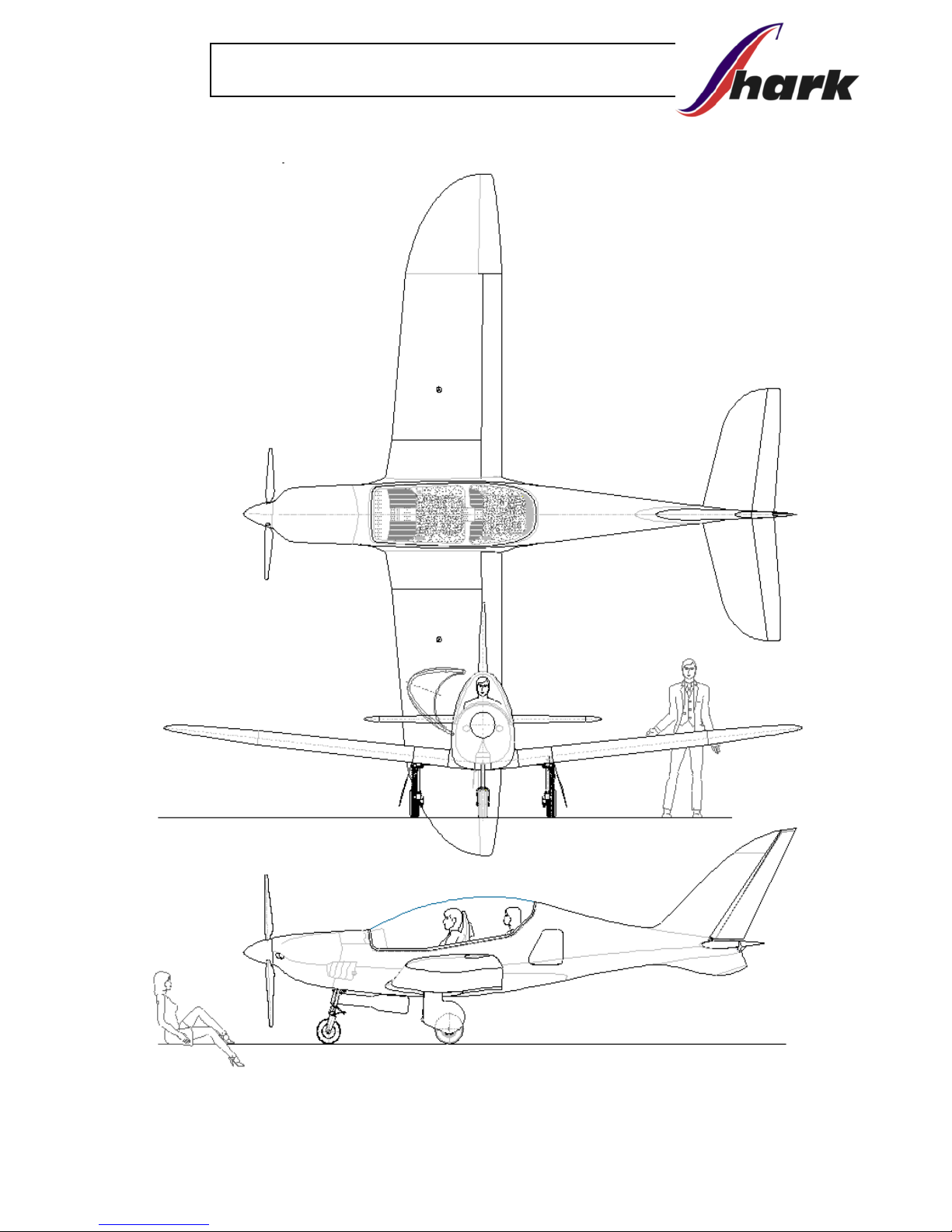
1.4. AIRPLANE BASIC DESCRIPTION
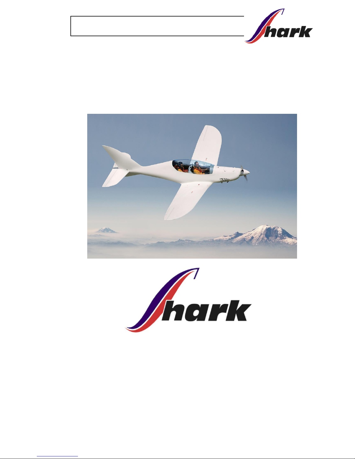
SHARK is an all-composite low-wing ultralight airplane with retractable
undercarriage, tandem seats configuration, designed for fast
cross-country flights.
Airplane is equipped with 100HP Rotax 912 ULS engine and one of
propellers acc. paragraph 7.8.
Wing span
7,9 m
Length
6,85 m
Height
2,3 m
Wing area
9,5 m2
MAC length
1,237 m
Swept wing angles
3,53° / 13,8° / 39,8°
Existing version of the airplane, approved by calculations and tests,
cover installation of engines Rotax 912ULS with optional equipment.
All versions are calculated and tested for MTOW 600kg, but this specific Flight
manual has defined limits, valid for UL category in Czech Republic under LAA
CZ.
Marking of a specific airplane version is defined in introduction of
this flight manual. Deviations from the basic version are
described in the following box:
Page 13
Page 1-3
Flight manual UL aircraft
1.5. THREE VIEW DRAWING
Page 14

Page 15
Strana 2-1
Flight manual UL aircraft
2. LIMITATIONS
All speeds shown in this manual are indicated speeds. The conversion
table in chapter 5.1. can be used to get the real speeds.
2.1. AIRSPEED
Speed
IAS
km/h
CAS
km/h
VNE
Never exceed speed
327
333
VRA
Maximal speed in hard turbulence
249
250
VA
Maneuvering speed
175
170
VFE
Maximum speed with open flaps
143
140
WARNING: Above Maneuvering speed use only small deflections
of control surfaces - the airplane may be easily overloaded!
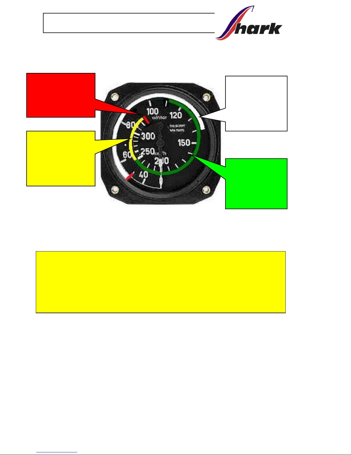
2.2. AIRSPEED INDICATOR MARKINGS
EFIS/EMS Dynon SkyView
NEVER EXCEED
SPEED:
327 - km/h
CAUTION RANGE:
249 - 327 km/h
NORMAL
OPERATION RANGE:
105 - 249 km/h
FLAPS OPERATING
RANGE:
50 - 143 km/h
Page 16
Page 2-2
Flight manual UL aircraft
2.3. ANALOG AIRSPEED INDICATOR MARKINGS
CAUTION:
All speeds in this manual are determined by primary airspeed
indicator displayed on EFIS (Dynon SkyView, FLYMAP). Analog
airspeed indicator, used as emergency one, may indicate slightly
different speeds – see item 5.1.
NORMAL
OPERATION
RANGE:
105 - 249
km/h
CAUTION
RANGE:
249 - 327
km/h
FLAPS
OPERATING
RANGE:
50 - 143
km/h
NEVER EXCEED
SPEED:
327m/h
Page 17
Page 2-3
Flight manual UL aircraft
2.4. ENGINE
SHARK is powered by 100HP ROTAX 912 ULS engine.
Airplane
Engine type
SHARK
ROTAX 912 ULS
Max. take-off power (kW)
73,5
Max. continuous power (kW)
69
Max. engine speed (5 min)
5 800 ot/min
Max. engine speed (continuous)
5 500 ot/min
Max. cylinder head temperature (°C)
150
Max. oil temperature (°C)
140
Oil pressure - minimum (bar)
0,8 below 3500 rpm
2,0 above 3500 rpm
Oil pressure: maximum, cold start
only (bar)
7
Oil pressure: normal operation (bar)
2,0 – 5,0
Fuel pressure: min-max (bar)
0,15 – 0,4
Operation range of outside
temperature
-25°C
+ 50°C
For more details see Operator’s Manual for all versions of Rotax 912
supplied with the engine.
WARNING:
Flying this aircraft must always be done with the possibility of a
safe landing due to loss of engine power.
The pilot is fully responsible for consequences of such failure
Page 18
Page 2-4
Flight manual UL aircraft
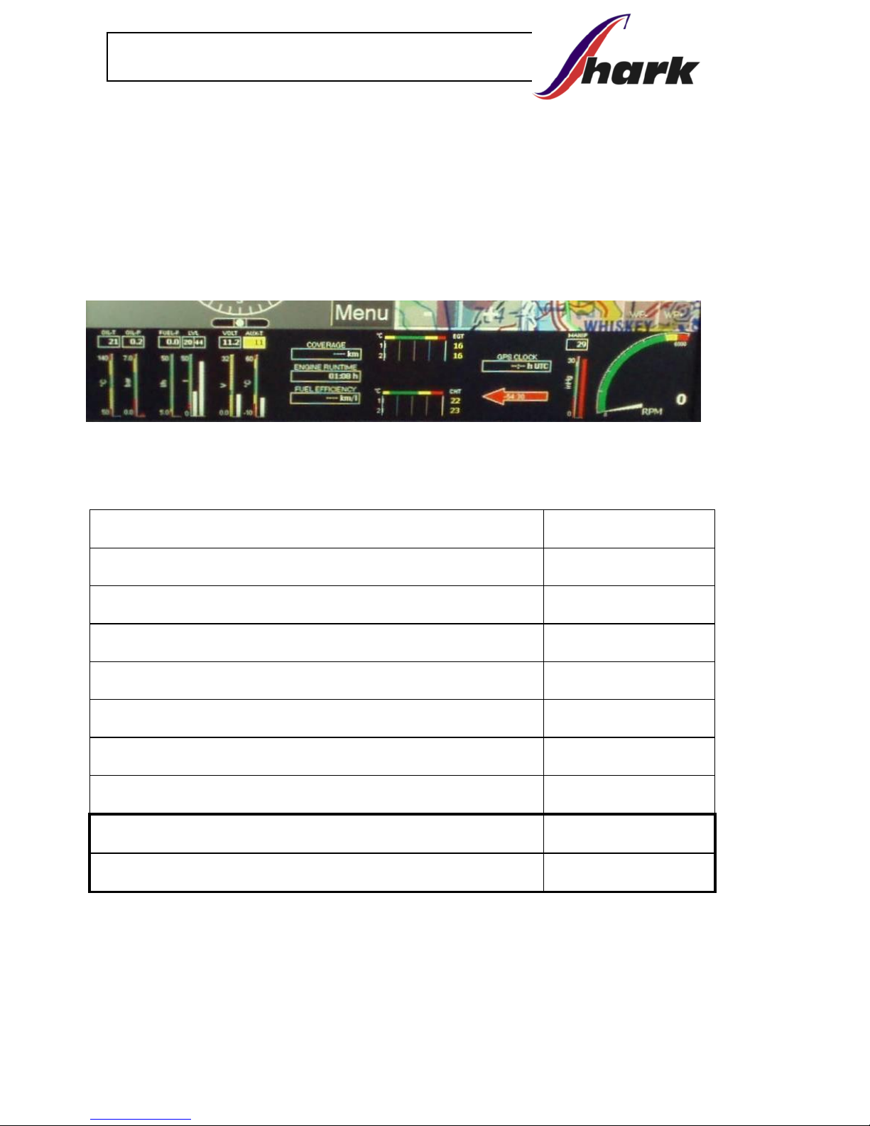
2.5. ENGINE INSTRUMENT MARKING
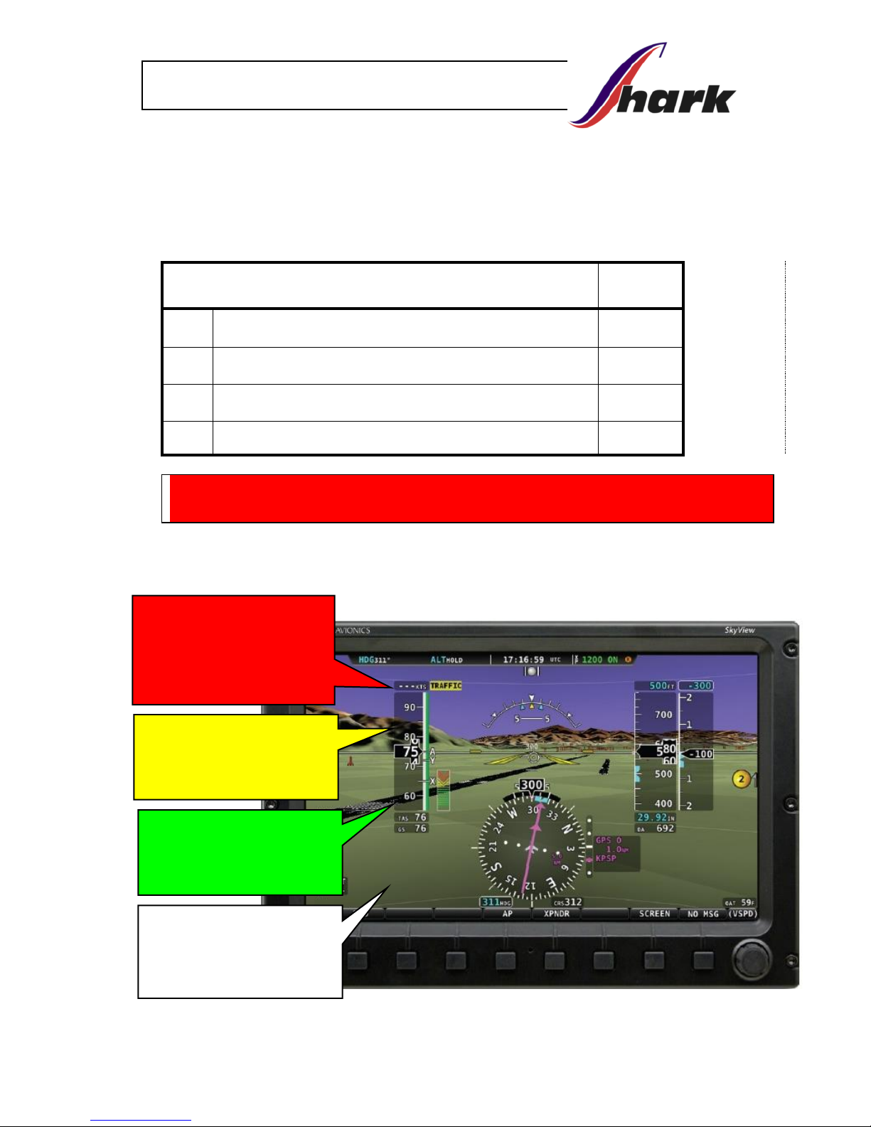
The airplane is equipped with the integrated engine display.
Values can be displayed in the integrated EFIS/EMS (Dynon SkyView,
FLYMAP, GARMIN ...), on separate EMS unit (MiniEIS, EMSIS, VIGILUS ...)
or on conventional imaging devices.
An example of FLYMAP engine operating variables:
Warning limits of Indicator Unit:
912 ULS
TACH - Max. RPM [1/min]
5800
EGT - Exhaust gas temperature [ºC]
860
CHT - Cylinder head temperature [ºC]
150
OIL - Oil temperature [ºC]
140
- Oil pressure, max [bar]
7
- Oil pressure, min [bar]
0,8
- Oil pressure, normal [bar]
2 – 5
ERT - Engine room temperature [ºC]
70
TFUEL - Fuel temperature [ºC]
70
normal values are displayed in green color
values with higher attention are displayed in yellow
critical values are displayed in red
Page 19
Page 2-5
Flight manual UL aircraft
2.6. WEIGHT LIMITS
Empty weight: standard version (kg)
290 kg
Empty weight: fully equiped (kg)
320 kg (max 325 kg)
Max. take-off weight:
NO Ballistic Recovery System installed (kg)
450 kg
Max. take-off weight:
Ballistic Recovery System installed (kg)
472,5 kg
Max. crew weight:
calculated for max take-off weight (kg)
177 kg
Min. crew weight: (kg)
55 kg
Max. crew weight: rear seat (kg)
95 kg
Max. one pilot weight: (kg)
110 kg
Max. weight in baggage compartment (kg)
- for solo flight from front seat
25 kg
Max. weight in baggage compartment (kg)
10 kg
MAXIMAL CREW WEIGHT (kg)
depends on fuel and baggage quantity
Fuel tank
filling
Fuel gauge
indication
full
3/4
1/2
1/4
30 min
of flight
Fuel quantity
in liters
100
75
50
25
5
kg
72
54
36
18
3,6
Baggage
weight
Max: 10 kg
½ : 5 kg
Without baggage
Max. crew weight has to be written indelibly for specific measured weight of airplane.
WARNING:
Do not exceed these weight limits. Pay attention to fuel quantity,
especially when 2 persons are on board.
DO NOT EXCEED maximum take-off weight.
Page 20
Page 2-6
Flight manual UL aircraft
2.7. CENTER OF GRAVITY (CG)
The values for ready to fly airplane (including fuel, crew, baggage).
Front center of gravity limit
16 % MAC
Rear center of gravity limit
34 % MAC
See Section 6 for center of gravity calculation.
Retraction of landing gear moves CG 0,5-1% backwards.
2.8. APPROVED MANEUVERS
The Shark Airplane may perform:
- turns required for normal flying
- practicing falls
- steep turn (max. bank 60°)
WARNING:
All maneuvers must be performed with a positive overload
because the fuel and lubrication system is designed for positive
overloads. All maneuvers must be performed in a maneuver
envelope with maximum positive + 4g and negative -2g overload.
WARNING: Aerobatics, intentional stalls and spins are prohibited.
Maximum angle of bank: 60°
2.9. MANEUVERING LOAD FACTOR G
Flap up 0°
Maximum positive center of gravity load factor
+ 4
Maximum negative center of gravity load factor
- 2
Flaps down
Maximum positive center of gravity load factor
+ 2
Maximum negative center of gravity load factor
0
2.10. FLIGHT CREW
Minimum crew on board 1 pilot
Maximum crew on board 2 persons
Page 21
Page 2-7
Flight manual UL aircraft
2.11. KIND OF OPERATION
WARNING: Only VFR day flights are permitted.
WARNING:
IFR flights and flying in clouds is prohibited.
Flights in icing conditions are prohibited.
2.12. FUEL
2.12.1. Approved fuel types
Premium unleaded automtive fuel (Natural 95 in Czech - Standard spec.
for Automotive Spark-Ignition Engine Fuel, ASTM D 4814) or AVGAS 100
LL.
NOTE: Due to the higher lead content in AVGAS, the wear of the valve
seats, the deposits in combustion chamber and lead sediments in the
lubrication system will increase. Therefore, use AVGAS only if other
fuel types are not available.
For more details see Operator’s Manual for all versions of Rotax 912
supplied with the engine.
2.12.2. Fuel tanks capacity
Fuel tank types
Standard
Long Range
Fuel tank capacity (each wing tank)
50 liters
75 liters
Total fuel capacity
100 liters
150 liters
Unusable fuel
1 liter
Page 22
Page 2-8
Flight manual UL aircraft
2.13. OTHER LIMITATIONS
Max. crosswind component
16 knots
( 8 m/s )
Max. wind in runway direction
30 knots
( 15 m/s )
Maximum outside temperature
50° C
Minimum outside temperature
-25° C
Heavy rain or excessive moisture can cause mild decrease of airplane
performance. During these poor conditions we recommend to increase take-off
and landing speed approximately about 10 km/hour.
WARNING: No smoking on board!
Page 23
Page 2-9
Flight manual UL aircraft
2.14. PLACARDS
Production label:
SHARK.AERO
SHARK UL 034/2017
… The serial number of the particular
airplane (total serial number / year of manufacture)
Registration label:
Matriculation:
Producer: SHARK Aero spol. s r.o.
Type/Name : SHARK
Production number/year:
Empty weight: kg
Max. take-off weight: 472,5 kg
Front and rear seat / luggage weight limit label:
Front seat limit
Rear seat limit
Luggages limit
solo
110 kg
0 kg
25 kg
2+lugg.
110 kg
kg
10 kg
2 max
110 kg
kg
0 kg
Basic information placards:
This product is not subject of
the Czech Civil Aviation Authority approval
and is operated at the user's own risk.
AEROBATICS MANEUVERS AND
INTENTIONAL SPINS ARE PROHIBITED
Page 24
Page 2-10
Flight manual UL aircraft
Basic LAA CZ label:
OPERATION INFORMATIONS AND LIMITS - speeds IAS
Matriculation
Empty weight
kg
Max. take-off weight
kg
Max. payload
kg
Max. baggage weight for 1 pers. / 2. pers.
25 / 10
kg
Min / Max. pilot weight
55 / 110
kg
Max. passanger weigh (rear seat)
95
kg
Stalling speed with flaps VSO
50
km/hour
Max. speed with not-retracted undercarriage V
LO
150
km/hour
Maximum flap extended speed V
FE
143
km/hour
Max maneuvering speed V
A
175
km/hour
Max speed in hard turbulency V
RA
249
km/hour
Never exceed speed V
NE
327
km/hour
MAXIMAL CREW WEIGHT (kg)
DEPEND ON FUEL AND BAGGAGE QUANTITY
Fuel tank
filling
Fuel gauge indication
full
3/4
1/2
1/4
30min
of flight
Fuel quantity in liters
100
75
50
25
5
Baggage
weight
Max: 10 kg
½ : 5 kg
Without baggage
Engine limit information:
ENGINE SPEED
Max. take-off (max 5min) 5 800 rpm
Max. continuous 5 500 rpm
Idling 1 400 rpm
Page 25
Page 2-11
Flight manual UL aircraft
FUEL TANK VOLUME. LIMIT - standard FUEL TANK VOLUME LIMIT - LongRange
BAGGAGE WEIGHT LIMIT
TYRES PRESSURE
- on the wing, walk-around area for access to
cockpit
- on the aerodynamic control surfaces
Rescue system info - on the tail / small on the Rescue System cover
tyre 300 kPa
Baggage
max. / solo
flight
10 / 25 kg
50 liters
Natural 95
min. MON 85 RON 95
75 liters
Natural 95
min. MON 85 RON 95
Page 26

Page 27

Page 28

Page 29

Page 3-1
Flight manual UL aircraft
3. EMERGENCY PROCEDURES
This section provides checklist of emergency situations which may
occur. Emergency situations caused by airplane or engine malfunction
are extremely rare with proper preflight inspections and maintenance.
However, an emergency situation may occur. The guidelines,
described in this section, should be applied to solve the problems. All
air speed values in this chapter are presented in km/h - Indicated
Airspeed.
3.1. ENGINE FAILURE AND EMERGENCY LANDING
3.1.1. Engine failure during take-off run
- throttle reduce to idle
- ignition off
- master switch off
- brakes as required
3.1.2. Engine failure during take-off
- airspeed - 120 km/h
- landing site - below 150 ft - land straight ahead
- above 150 ft - choose suitable landing area
in the runway direction or
nearest suitable site clear of
obstacles.
- master switch off
- ignition off
- fuel tank valve shut
- fuel pump off
- flaps extend as needed
- undercarriage extended / check
- safety belts tighten
after touchdown:
- brakes as required
Page 30

Page 3-2
Flight manual UL aircraft
3.1.3. In-flight engine failure
- airspeed 120 km/h
- trim trim
- landing site selection select
Check situation, if master switch and ignition are on and fuel valve is
open, continue according to procedure 3.2. (in-flight engine start) or by
emergency landing according to procedure 3.1.2 (if the engine cannot
be started up).
3.1.4. Carburettor icing
- airspeed 140 km/h (optimal)
- throttle try to find RPM with smallest loss of power
- leave the icing area (if possible)
- after 1-2 minutes increase slowly engine power to cruise speed
- when engine power is not recovered, land on the nearest airfield or
off-airfield following the procedure described in Chyba! Nenašiel
sa žiaden zdroj odkazov.
3.2. IN-FLIGHT ENGINE RESTART
- airspeed 120 km/h
- master switch on
- fuel tank valve open tank with more fuel (check)
- choke closed (as the engine is warm)
- fuel pump on
- throttle idle (when choke is activated), 1/3 of
travel otherwise.
- ignition on
- starter start up
- if the engine cannot be started up (not enough power from battery),
increase the airspeed to 150-170 km/h to rotate the propeller to
support the engine starting.
WARNING: Loss of height needed for in-flight engine starting is
approximately 600 ft.
Page 31

Page 3-3
Flight manual UL aircraft
3.3. FIRE
3.3.1. Engine fire on the ground
- fuel tank valve off
- throttle full
- ignition off
- master switch off
- leave the airplane and extinguish fire (if possible)
- fire damage inspect
WARNING:
DO NOT TAKE ANY FURTHER FLIGHT BEFORE THE FIRE CAUSE
HAS BEEN DETERMINED AND REPAIRED.
3.3.2. Engine fire during take-off
- throttle idle
- fuel tank valve off
- if already airborne keep airspeed 120 km/h and land
- brakes as necessary to stop the airplane
after the airplane stops:
- throttle full
- ignition off
- leave the airplane and extinguish fire (if possible)
3.3.3. Engine fire in flight
- fuel tank valve off
- throttle full
- airspeed increase – try to extinguish the flames.
Do not exceed VNE
- landing site selection use nearest airfield or a suitable
landing site for emergency landing
- ignition off
- master switch off
- airspeed 120 km/h
- wings flaps extend as needed
- undercarriage extend/check
- safety belts tighten
- perform emergency landing
- leave the airplane and extinguish fire (if possible)
WARNING: DO NOT ATTEMPT TO RESTART THE ENGINE
Page 32

Page 3-4
Flight manual UL aircraft
WARNING:
DO NOT TAKE ANY FURTHER FLIGHT BEFORE THE FIRE CAUSE
HAS BEEN DETERMINED AND REPAIRED REPAIRED.
3.3.4. Cockpit / electrical fire
- cockpit vents and windows open all vents and windows to
remove smoke from the cockpit
- electric equipment switches switch off all electric equipment
not needed for safe landing
Land as soon as possible. Extinguish fire as soon as possible.
3.4. GLIDING
Optimal gliding speed
125 km/h
Gliding ratio (at 125 -135 km/h), no flaps
1 : 12
3.5. PRECAUTIONARY LANDING
- choose suitable landing site, evaluate wind (direction and speed),
surface, slope and obstacles
- perform a fly-over at a speed of 125 km/h, above the selected
landing site at suitable height (150 ft recommended), observe the
landing site
- follow normal landing checklist and land
after touchdown perform following:
- ignition off
- master switch off
- fuel tank valve off
- brakes as required
3.6. BLOWN-OUT TIRE LANDING
Use normal approach and landing procedure, keep damaged wheel
above the ground during the flare as long as possible using ailerons (or
elevator for the nose wheel).
Page 33

Page 3-5
Flight manual UL aircraft
3.7. LANDING WITH DAMAGED LANDING GEAR
Use normal approach and landing procedure, keep the damaged
wheel, or unopened wheel, or wheel with unlocked leg, above ground
during the flare as long as possible using ailerons (or elevator for the
nose wheel).
3.8. LANDING GEAR RETRACTION MALFUNCTION
- switch off landing gear circuit switch/breaker
- climb to safe altitude where you can continue flight without stress
- switch on landing gear circuit/breaker and activate landing gear
opening procedure – speed bellow 130 km/h
- check visually locked landing gear struts
- do not use airplane if landing gear system is not checked,
repaired and adjusted by authorised person.
Note: Electric system of landing gear has safety switch installed,
activated by air pressure from pitostatic tube. This system
block retracting below speed 115 km/h, and activates warning
sound and blinking alarm if all 3 legs are not opened and
locked below this speed.
3.9. LANDING GEAR OPENING MALFUNCTION
If any malfunction occurs during opening procedure of landing gear
- switch off landing gear circuit switch/breaker
- climb to safe altitude where you can continue flight without stress
- reduce and keep speed on 120 km/h
- switch on landing gear circuit switch/breaker and activate landing
gear opening procedure
- if landing gear is not fully opened and locked, activate retracting
of LG, and then try to open it again. Combination of plus and
minus G load can help release the system if there is a
mechanical failure
- if some leg of landing gear is not fully open or locked, use
landing gear emergency release. Open small flaps, reduce
speed to 120 km/h, switch off landing gear circuit, pull off red
emergency release handle of dysfunctional leg
- check visually locked landing gear struts
Page 34

Page 3-6
Flight manual UL aircraft
- if you have any doubts the landing gear is properly open and
locked, check visually yellow-black flag-arrow via check windows
- this visual check is superior to electronic information
- in case of one leg stays locked, safe procedure is to retract other
legs as well, and perform belly landing. When landing on grass,
close flaps, stop engine with 2 blades proppeler in horizontal
position to reduce demage to minimum
CAUTION:
When landing gear emergency release is used, landing gear stays
open without possibility to retract it without re-assembling by authorised
technician!
3.10. VIBRATIONS FROM ENGINE OR OTHER ENGINE
PROBLEM
Vibrations:
- use engine power with minimal vibrations
- in case the airplane has in flight adjustable propeller try to find in
manual control regime angle with minimal vibrations
- land as soon as possible, consider off-airfield landing if vibrations
increase
Oil pressure drop - probability of engine failure. In this case reduce
engine power and land as soon as possible (before the failure occurs),
consider off-airfield landing.
3.11. INADVERTENT ICING ENCOUNTER
- throttle increase above normal cruise settings
- course reverse or alter as required to avoid icing
- altitude climb (if possible)
3.12. EXTREME TURBULENCE ENCOUNTER
- airspeed recommend 200 km/h (VRA=249 km/h)
- safety belts tighten
- loose objects fixed
EMERGENCY LANDING GEAR EXTRACTING
Page 35

Page 3-7
Flight manual UL aircraft
3.13. ELECTRICAL SYSTEM MALFUNCTIONS
In case of electric system malfunction we have 3 indicators providing
informations about system status.
Charging indicator - red LED on left top edge of instrument panel.
Providing primary information about electric regulator status.
- normal function: with the ENGINE START switch on, and engine
turned off, the LED is blinking, because generator doesnt provide
energy. With running engine, generator provides energy, regulator
provides volts and ampers to appliances and for battery charging,
and LED stops blinking.
- failure: is signalised by blinking of red LED, while the engine is
running, it signalizes the regulator doesn´t provide energy.
Appliances take energy from main battery or backup batteries, which
have limited cappacity. The flight may continue for several minutes.
Carburator engine will run even in full failure of electric system,
energy for spark plugs is generated by magnetos, independent on
the rest of the electric system.
Engine with injection fuel system is limited by battery capacity, as it
needs power for high pressure fuel pump and electronic control unit.
Appliances requiring electric power will run until the batteries run out.
With both batteries discharged, electric control of landing gear will be
inoperative. Emergency opening of landing gear manually will be
necessary. Flaps will be inoperative, landing will be possible with
closed flaps only. Radio and transponder will be inoperative too.
Voltmeter: when the engine is off, voltmeter shows battery voltage.
Normal value is between 12 to 13,5 V. Below 11 V the battery is empty
and engine start will probably not be possible. With a running engine,
voltmeter shows voltage provided by regulator. Normal level is
13,5 - 14,4 V. If failure of regulator occurs, followed by blinking
indicator, it is necessary to check volts, if they gradually decrease with
time, it signalise loss of battery voltage, battery is discharged. If battery
voltage drops under 10,5 V, some instruments stop working. Damage
of battery can occur in the same time.
Ammeter: shows current flowing from or to the battery. With engine
off, ammeter indicates possitive values, battery is providing current, is
discharging. Normal level is 1 to 6 Amps, depends on the number of
devices turned on. With running engine, batteries are charged,
Page 36

Page 3-8
Flight manual UL aircraft
ammeter shows negative values. When the battery is low, ampers can
reach -15 Amps. When battery is charged, current slowly decreases.
After few minutes of flight, battery is charged, and ammeter starts
showing zero values. This indicates fully charged battery.
In case of regulator failure, when current is provided by battery, the
ammeter shows plus Amps.
Procedure: if charging indicator is blinking - switch off all instruments
unnecessary for the flight. Make safety landing at the closest airport
and fix the problem.
3.14. INADVERTENT STALL AND SPIN RECOVERY
Stall or spin should not occur during normal flight and both
are prohibited.
3.14.1. Stall recovery
- push down the nose of airplane by pushing the control stick – to
increase speed
- gradually increase power
Loss of altitude in straight direction after stall is:
450 - 500 ft = 137 - 150 m
3.14.2. Spin recovery
WARNING:
Spin characteristics of the airplane have not been tested.
A procedure bellow is for information purposes only.
- throttle idle
- aileron neutral
- rudder opposite to rotation
- control stick pushed
Once the rotation is stopped, get rudder back to neutral position and
establish a level flight.
Page 37

Page 3-9
Flight manual UL aircraft
3.15. USE OF RESCUE SYSTEM
- engine off
- pull red handle of ballistic recovery system placed between legs
of both pilots
- protect your body
WARNING: Rescue system is secured by pin with red flag
„REMOVE BEFORE FLIGHT“, which needs to be removed before
every flight. In case you forget to pull the pin out, remove it before
use.
CAUTION: When the rescue system is used, damage of airplane
always occures.
Page 38

Page 39

Page 4-1
Flight manual UL aircraft
4. NORMAL PROCEDURES
4.1. PRE-FLIGHT INSPECTION
4.1.1. Cockpit
- Master switch and ignition off
- Attachment and position of seats check, adjust
- Safety belts inspect
- Instruments and equipment inspect
- Control stick inspect, freedom of movement
- Rudder pedals inspect, freedom of movement
(consider nose wheel control)
- Rudder and aileron cable control inspect
- Engine control inspect, freedom of movement
- Brakes function
- Fuel check (level)
- Condition of the composite shell check
and transparent canopy
- Oil quantity between MIN and MAX marks
Page 40

Page 4-2
Flight manual UL aircraft
4.1.2. Wing
- Wing inspect surface and damages
- Hinges, saving inspect
- Ailerons inspect, freedom of movement
and deflections
- Flaps, hinges, control tube, bolts, nuts, securing inspect
- Fuel tank tightness and caps inspect
- Pitot tube inspect
- Fuel tank ventilation holes in flap hinges inspect
4.1.3. Landing gear
- Landing gear and brake system inspect
- Landing gear leg and attachment inspect
- Shock absorber of the nose landing gear inspect
- Rubber shock absorber of the main landing gear inspect
- Retracting system of undercarriage inspect
(locking strut, gas springs, steel springs, cables
for retracting, emergency locks + bowdens,
servo for front leg, sensors for opened and
retracted position)
- Doors of retractable undercarriage inspect
- Tire pressure check
- Main and rear wing pins securing inspect
- Fuel filters inspect
- Connection and condition of fuel hoses inspect
- Connectors and wiring to sensors in fuel tank inspect
4.1.4. Powerplant
- Engine, propeller general condition inspect
- Safety pins and wires inspect
- Engine mount and engine bed inspect
- Exhaust silencer inspect
- Ignition system inspect
- Fuel system - hoses and pump inspect, drain the system
- Cooling fluid inspect
- Propeller turn (until you hear burp sound)
- Oil level check inspect, refill if needed
Page 41

Page 4-3
Flight manual UL aircraft
4.1.5. Control cables
- Rudder control cables inspect condition and tension
- Turnbuckles, bowdens, safety wire inspect
4.1.6. Tail unit and fuselage
- Tail unit surface and damages inspect
- Control surfaces freedom of movement, deflection
- Trim tab inspect
- Nut + securing on stabilizer rear pin inspect
- Bolts + nuts + controls inspect
- Fuselage inspect surface
4.1.7. Turning on of electric devices
- the audio sequence is played when the EFIS SkyView unit is
turned on. It tests the sound. Radio must be turned on.
- when the landing gear circuit is turned ON, the signal diodes start
blinking and acoustic signal is played. This checks functionality of
these devices.
- when flaps circuit is turned ON, top green LED starts blinking, and
it is necessary to press related button. If flaps are not in zero
position, they will retract to zero position.
4.2. ENGINE STARTING
- pre-flight inspection completed
- safety belts adjust and fasten
- instruments values check, settings
- canopy closed, locked
- master switch switch on
- fuel tank valve (left / full tank) open
- choke activate (cold engine only)
- throttle Idle for cold engine, 1/3 of travel for warm engine
- cowl flaps open
- pre-heating of carburettors as required
- fuel pump on (if left tank is used)
- control stick pulled
- brakes on
- propeller area “clear”
- ignition switch on
- starter turn on for max 10 sec, then 2 min. cooling
- after engine start up set the idle speed
Page 42

Page 4-4
Flight manual UL aircraft
- instruments check out indication
(oil pressure must rise within 10 seconds)
- choke switch off slowly (cold engine only)
- avionics and other switches switch on as required
4.2.1. Engine warm-up and test
- Warm up to operating temperature - first at idle or 2000 RPM for
2 minutes, then at 2500 RPM to reach oil temperature of 50 °C.
- Check out temperature and pressure values - must be within
operating limits all the time.
- Check out the maximum power - speed around 5000 RPM
depends on used propeller
- Check out ignition (magnetos) - set 4 000 RPM
- drop should not exceed 300 RPM on either magneto
- difference between magnetos shouldn´t exceed 120 RPM
- Check idle - 1600 RPM ±100
CAUTION: Perform the engine check on suitable terrain heading
upwind. Consider also safety of other persons. Do not operate the
engine for longer time than necessary and allow sufficient cooling
before switching off.
4.3. BEFORE TAXIING
Check from left to right:
- seat adjust
- headset connected
- seatbelts locked, tightened
Left side of cabin:
- items below armrests secured, fixed
- check copilot if ready headset, seatbelts
- cabin closed, locked, front + rear
- cabin windows closed, front + rear
- kneeboard + pen write down data, time
- fuel tank valve left
- throttle 2500 rpm
- choke closed
- cooling (cowl flaps) opened
- ventilations - airstream opened
- items below knees secured, fixed
Page 43

Page 4-5
Flight manual UL aircraft
Left side of instrument panel:
- items in drawer secured, fixed
- flaps lever visual check 0,1,2,3, adjust 1 - take-off position
- landing gear breaker ON
- position of landing switch DOWN (neutral)
- landing lights 3 green
- landing gear struts arrows visual check of locked position
- charging control light off –>check
- adjustable propeller auto, take-off or manual, set
min. angle
Middle of instrument panel:
- GPS ON, adjust
- EFIS ON, adjust
- QNH adjust
- AOA/stall warning ON, check function
- EMS ON, check pressure and temperature – in green
- fuel amount quantity check, minimum 10 litres in left fuel tank
- radio ON, adjust frequency, check function
- intercom ON if passenger is on board, check function
- transponder ON, adjust (7000)
- magneto 1+2 ON
- master switch ON
Right side of instrument panel:
- EFIS alarm LED no warning
- backup altitude adjust QNH
- switches/breakers ON
- fuel pump ON
- lights ON
- optional instruments check + adjust
(ELT, CO detect, FLARM, IPHONE..)
Right side of cabin:
- ventilation - airstream open
- heating according to need
- ventilation open
- control stick free movement elevator + ailerons
- trim neutral
- items below armrest fixed, secured
- items below knees fixed, secured
Page 44

Page 4-6
Flight manual UL aircraft
Middle of the cabin:
- pedals adjust, free movement
- brakes press, check function
- parking brake open
- handle of rescue system remove pin (at front seat)
- runway and take-off area check of availability
- radio report line-up
4.4. TAXIING
The maximum taxiing speed is 10 km/h (walking speed). Always check
brakes functionality as soon as the airplane start taxiing. Do not use
too much brake in snowy conditions, melting ice can freeze on brake
discs.
Check the temperatures in summer to avoid overheating of the engine.
In case of high temperatures and VAPOR LOCK risk, open the oil
check cap.
In temperatures above 70 oC there is a risk of VAPOR LOCK in the
engine compartment, let the engine cool down.
4.5. CHECK ON HOLDING LINE
- Cabin closed
- Control check, free
- Fuel selector left
- Mouth opened
- Flaps position 1
- Propeller take-off
- Circuit breakers set (as needed)
- Engine pressure and temperature check
- Fuel pump ON
- Trim neutral
- Handle of rescue system release
- Radio report
Page 45

Page 4-7
Flight manual UL aircraft
4.6. NORMAL TAKE OFF
- Pedal brakes release
- Throttle full power
Drive straight ahead. Lift slightly nose wheel at about 50 km/h IAS.
Take off at speed around 90 km/h, accelerate and climb.
Do not climb until speed 115 km/h is reached.
WARNING: Do not take-off when engine is not running smoothly
or runway is occupied.
- initial climb speed 120 km/h
- engine speed reduce to max 5 500 RPM
- engine instruments check
- landing gear retract above 150 ft, when speed is over
120 km/h, check 3 red marks
- wing flaps flaps up above 150 ft, at speed 120 km/h
- trim trim
- fuel pump off, when level flight
Note: In landing gear electric circuit is installed the pressure switch,
connected to pitotstatic sytem, and adjusted to speed 115 km/h. This
should prevent unintentional retraction of landing gear on the ground.
Control unit does not retract landing gear, until the speed is reached.
Opening of landing gear is not blocked by this switch. It works at any
speed.
If all 3 wheels of landing gear are not opened and locked below this
speed, pressure switch activates sound and light warning system.
Inspection of opened and properly locked landing gear is realized
visually via small check windows.
4.7. CLIMB
- throttle 5 500 RPM max
- airspeed 120 to 180 km/h as required
(130 km/h best angle, 180 km/h best climbing)
- temperature check maximum, if needed reduce power to
avoid overheating
Page 46

Page 4-8
Flight manual UL aircraft
4.8. CRUISE
- bring the airplane into horizontal flight
- in-flight adjustable propeller 4 000 – 5 500 RPM
- throttle 24 inHg – full (as required)
- airspeed as required
- engine instruments check
- fuel tank valves switch between tanks when necessary
WARNING:
Do not forget to switch the wing tanks supplying the engine on regular
basis to prevent fuel starvation.
When both fuel tanks are full or almost full, always select the left tank.
Followed values are recommended for ideal airplane use:
Standard SHARK version
Engine Rotax 912 ULS
Engine
speed
(1/min)
Power
(kW)
Torque
(Nm)
Intake
pressure
(in Hg)
Take-off power
5800
73,5
121,0
27,5
Max. continuous power
5500
69,0
119,8
27
75 %
5000
51,0
97,4
26
65 %
4800
44,6
88,7
26
55 %
4300
38,0
84,3
24
4.9. APPROACH
4.9.1. Descent
- throttle as required
- engine instruments check
WARNING:
Avoid prolonged operation with IDLE during the flight as the engine
may become overcooled and lose the power.
If higher descent is needed, there is possbility to extend flaps under 140 km/h,
and extend the undercarriage. Side slip is not efficient, steep descend is
reached with flaps III.
Page 47

Page 4-9
Flight manual UL aircraft
4.10. DOWNWIND
- power 4 000 – 5 000 rpm
- airspeed reduce to 120-130 km/h
- engine instruments check
- fuel tank valve left, if there is enough fuel
- fuel pump ON, if left tank is selected
- safety belts tighten
- approach area and landing site situation check
- undercarriage open (3 green lights on)
visual check
- TWR report (3 green)
4.11. NORMAL LANDING
4.11.1. On Base Leg
- power 3 000 rpm, or according to need
- airspeed 120 km/h
- engine instruments check
- wing flaps take-off position ( position I )
- adjustable propeller take off position
- trim trim
- final leg airspace situation check
4.11.2. On Final
- airspeed 90 - 110 km/h
- power adjust as needed
- engine instruments check
- wing flaps landing position (II or III)
- trim trim
- check of landing site situation check
4.11.3. Landing
At a height 30 ft set the engine at idle speed.. Maintain speed of
90-100 km/h till the flare. When flaring at a height of 1-2 ft above the
ground, decelerate gradually by pulling the control stick backward till
the airplane lands. Keep pulling control stick to avoid immediate
contact of the front wheel with the ground.
Page 48

Page 4-10
Flight manual UL aircraft
4.11.4. After landing
- brakes use as needed
- wing flaps retract
- trim neutral
- flaps 0 or 1
- fuel pump off
4.11.5. Engine shut down
- power cool down the engine at 2 000 rpm (if necessary)
- avionics and other switches off
- ignition off
- master switch off
- fuel tank valve off - closed
- secure the airplane use parking brake, anchor an airplane,
or otherwise secure the airplane
against free movement.
4.11.6. Post-Flight Check
Check the airplane overall condition.
4.12. SHORT FIELD TAKE-OFF AND LANDING
PROCEDURES
Normal procedures can be followed for short take off. Use second
landing flaps setting together with approach speed 90 - 100 km/h.
4.13. BALKED LANDING PROCEDURES
- power max. 5 500 r.p.m
- airspeed 120 km/h
- engine instruments check
- wing flaps take-off (position 1)
- trim trim
- landing gear retract, check 3 red
- wing flaps retract in 150 ft
- trimming trim
- power max. 5 500 rpm
- climb 120 km/h
Page 49

Page 4-11
Flight manual UL aircraft
4.14. FUEL SYSTEM USE
Fuel system consists of two integral fuel tanks connected by fuel valve.
It is necessary to check fuel level and switch between tanks if needed.
According to requirements of engine manufacturer, the fuel system
possess of return line back to left fuel tank.
Electric fuel pump is installed behind fuel valve, it works for both tanks.
NORMAL USE of FUEL SYSTEM:
1. START FROM LEFT FUEL TANK
2. Switch between tanks as needed.
3. Fuel return system draws fuel back into left fuel tank, pilot
should check it continuously and switch back to left tank when
right one is nearly empty.
Do not start from right fuel tank, when left tank is full !!!
Excess fuel is returned to the full left tank and continues through
air vent out of the airplane.
4.15. REPEATED TAKE OFF
During the hot days problem with engine re-startup can occur, caused
by overheated fuel in the engine space,. Fuel starts boiling at 70-80°C.
Formed bubbles cause irregular fuel supply and engine can fails during
take off. This effect is called Vapour Lock.
To reduce risk of Vapour Lock, T connection of return line is placed in
highest position of fuel hoses.
Most of the airplanes has one or two temperature sensors inside
engine space and at fuel hose installed, so pilot has information about
these temperatures. Temperatures over 60 oC has yellow indication,
attention is needed, over 70 oC has red indication, risk of Vapour Lock.
Recommendation is to cool engine down, turn airplane against the
wind and run engine at idle, or stop it and let it cool down.
During hot days, we recommend to keep oil doors on upper
motorcowling open, to reduce this problem.
There is no risk of Vapour Lock during the flight. After take off engine
compartment cools down to temperature about 20 oC above the air
temperature. Engine producer recommend to use AVGAZ fuel in case
of Vapor Lock issues.
Page 50

Page 4-12
Flight manual UL aircraft
WARNING:
Before repeated take-off, during the hot days, is necessary to let
the engine run for a longer time and test full throttle to be sure
the engine fuel supply is without any problems.
4.16. HIGH SPEED FLIGHTS
Because Shark cruising speed is higher comparing to average
ultralights, there are certain risks the pilot should know about.
4.16.1. Turbulences
Shark economy cruise speed is 230 km/h. Normal cruise speed is
250 km/h and during faster flights 270 km/h. Max speed at full
continuous power is 280-300 km/h. Max speed depends on installed
systems as landing gear doors, airbox, injection, exhaust, weight,
temperature, altitude. Speed 250 km/h is possible to use for planning
long trips, it is acceptable even in turbulences.
Speed 270 km/h is comfortable for passangers when used in
conditions of lower turbulences.
Speeds over 280 km/h is comfortable only in very low turbulences.
In extremely high turbulences is good to reduce speed to 180-200
km/h.
4.16.2. Maneuvering
Maneuvering speed, when pilot can use full deflections of control
system, is 170 km/h, and airplane can reach load factor 4. Normal
cruising speed is significantly higher, so is is necessary to use smooth
movements of control system. Fast maneuvers can easily exceed
strength limits.
4.16.3. Landing gear opening
Approach and entering the traffic pattern is realized at speeds around
250 km/h. At downwind position is needed to decrease speed to 130
km/h, throttle at idle speed, and decrease speed in horizontal flight
without descending. Keep in mind it takes some time. Often mistake is
late power reducing, higher power than idle, descending. When
airplane is descending, speed doesnt decrease, and pilot can get into
the stress with next procedures. Unskilled pilots has problems with
higher speed range. They tend to fly at higher speeds, because of fear
of stall.
Page 51

Page 4-13
Flight manual UL aircraft
4.16.4. Propeller, engine RPM
Shark easily increase speed when maneuvering. Careful power control
is required to avoid engine overrun. This is important for fixed
proppeler, but keep it in mind with electrically adjustable propeller as
well, because it takes about 12 seconds to change blade angles from
minimum to maximum. Therefore even in constant speed mode is
recommended to reduce RPM when maneuvering and work smoothly
with throttle. Best propeller is hydraulically controlled, as it react very
fast, and risk of engine overrun is minimal.
4.16.5. Flaps
At traffic pattern, after opening landing gear, at speed 130 km/h, is
recommended to reduce speed to 120 km/h and open flaps 1. Often
mistake is higher speed, or speed fluctuation caused by turbulence, or
incorrectly pressed button on control panel. Pressure switch,
incorporated to flaps control system, is adjusted to 130 km/h. Over this
speed flaps will not open, and in case they are already opened,
warning will be activated. Therefore is needed to prove if flaps are
really open.
Another risk associated with flaps is balked landing. Pilot often in stress
applies full power, and instead of climb transforms power to speed.
Flaps are designed for max. speed 140 km/h. Higher speeds can
cause structure overload.
4.16.6. Landing gear retraction
Pressure switch is incorporated to control system of landing gear. It
prevents retration below speed 115 km/h. It is recommended to keep
airplane in light climb, after take-off, and wait till speed increase
enough. Pilot can hold the switch for landing gear on, and wait till the
airplane reaches required speed. Then the landing gear retraction
sequence automaticly starts. It is recommended to check visually, if
retracting procedure started – lights blink, or if underarriage is really
retracted – 3 red lights on. Flight with opened landing gear is possible,
landing gear doors was tested up to 230 km/h.
4.16.7. Flutter, high altitude flights
Fast airplanes can have flutter issues. Problems can occur specially
during higher speeds in high altitudes, because critical flutter speed
decreases with higher altitude.
Page 52

Page 4-14
Flight manual UL aircraft
Never exceed speed VNE = 327 km/h (calibrated speed
CSA = 333 km/h).
Table of VNE changes with increasing altitude:
For higher altitude flights, keep maximum allowed speeds indicated in
the previous table, or check TAS displayed by modern EFIS devices.
Height
m
0
1000
2000
3000
4000
5000
6000
7000
8000
TAS
km/h
327
327
327
327
327
327
327
327
327
IAS
km/h
327
310
298
285
271
263
248
238
224
Page 53

Page 5-1
Flight manual UL aircraft
5. PERFORMANCE
These flight performances are valid for the standard version of airplane at
maximum take-off weight 472,5 kg, normal flying technique and ISA
conditions (seal level, 15°C, 1013 hPa). Actual performance might be
different due to pilot skills, weather and airplane conditions.
WARNING: Variations in pilot technique as well as weather conditions
and airplane setting (e.g. propeller pitch) can cause significant
differences in flight performance.
5.1. AIRSPEED INDICATOR SYSTEM CALIBRATION
Primary airspeed indicator – EFIS (SkyView, Flymap ...)
IAS km/h 50 60 70 80 90 100 120 140 160 180 200 220 240 260 280 300 320 327
CAS km/h 65 76 81 88 93 104 122 137 156 174 202 218 240 263 284 305 326 333
Changing from cruise to take-off or landing configuration does not affect an
error of air speed indicator.
IAS
CAS
km/h
km/h
VS0
50
65
Stall speed in landing configuration
VS1
75
85
Stall speed in clean configuration
VFO3
100
104
Maximum speed for flap extending III
VFO2
110
113
Maximum speed for flap extending II
VFO1
120
122
Maximum speed for flap extending I
VLO
130
130
Maximum speed for extending and retracting
landing gear
VFE
143
140
Maximum flap extended speed
VA
175
170
Design maneuvering speed
VC
267
270
Design cruise speed- gust intensity loading
VRA
249
250
Maximum turbulence penetration speed
VH
280
284
Maximum speed in level flight at maximum
continuous power.
VNE
327
333
Never exceed speed
Page 54

Page 5-2
Flight manual UL aircraft
All speeds described in this manual are written as IAS speed, displayed by
primary airspeed indicator!!!
IAS - indicated speed of flight, indication of airspeed indicator in your airplane
CAS - calibrated speed, real speed of flight
(in zero flight level ISA) = compensated for indicator and aerodynamic error
5.2. STALL SPEED
Stall speed valid for airplane weight 472,5 kg and wing level flight.
Deflection
indicated
Stall speed
km/hour IAS
km/hour CAS
Flaps up
0°
75
85
Flap take-off position
20°
I
68
80
Flaps
30°
II
53
68
Flaps
40°
III
50
65
5.3. TAKE-OFF DISTANCE
5.3.1. In flight adjustable prop. NEUFORM TXR2-V-70
Flaps position 20°
Take-off run
Total take-off distance to
50 ft
Grass surface
125 m
225 m
Paved surface (concrete / asphalt)
105 m
205 m
Flaps position 30°
Take-off run
Total take-off distance to
50 ft
Grass surface
110 m
210 m
Paved surface (concrete / asphalt)
100 m
200 m
Flaps position 0°
Take-off run
Total take-off distance to
50 ft
Grass surface
270 m
300 m
Paved surface (concrete / asphalt)
240 m
270 m
Page 55

Page 5-3
Flight manual UL aircraft
5.3.2. In flight adjustable prop. Woodcomp SR3000/2WN
Flaps position 20°
Take-off run
Total take-off
distance to 50 ft
Grass surface
130 m
225 m
Paved surface (concrete/asphalt)
110 m
210 m
5.3.3. On ground adjustable prop. DUC SWIRL 1680
Flaps position 20°
Take-off
run
Total take-off
distance to 50 ft
Grass surface
185 m
290 m
Paved surface (concrete/asphalt)
160 m
270 m
Page 56

Page 5-4
Flight manual UL aircraft
5.4. LANDING DISTANCE
Flaps position 40°
Landing
ground roll
Total landing distance
from 50 ft
Grass surface
120 m
245 m
Paved surface (concrete / asphalt)
120 m
240 m
Flaps position 30°
Landing
ground roll
Total landing distance
from 50 ft
Grass surface
150 m
290 m
Paved surface (concrete / asphalt)
150 m
290 m
Flaps position 20°
Landing
ground roll
Total landing distance
from 50 ft
Grass surface
175 m
355 m
Paved surface (concrete / asphalt)
175 m
355 m
Without flaps (flaps 0°)
Landing
ground roll
Total landing distance
from 50 ft
Grass surface
210 m
530 m
Paved surface (concrete / asphalt)
210 m
530 m
5.5. RATE OF CLIMB
Altitude
Neuform
TXR2-V-70
Woodcomp
SR3000/2W
N, KW 20N
DUC SWIRL
1680
Max. rate of
climb speed
(km/hour IAS)
0 ft
7,5 m/s
6,5 m/s
5,1 m/s
185 km/h
1470 ft/min
1270 ft/min
1000 ft/min
3000 ft
6,2 m/s
5,2 m/s
3,8 m/s
185 km/h
1220 ft/min
1020 ft/min
745 ft/min
With flaps – take off configuration
0 ft
4,7 m/s
3,8 m/s
2,9 m/s
130 km/h
920 ft/min
745 ft/min
570 ft/min
Page 57

Page 5-5
Flight manual UL aircraft
Rate of climb diagram m/s (shows the best speeds for climbing with and without flaps).
5.6. CRUISE, ENDURANCE, RANGE
SHARK Rotax 912 ULS - 100 HP
Measured 2010-07-22 Pekár
Regime
Long range
cruise
Economic
cruise
Medium
cruise
Fast
cruise
Max. cruise
55%
65%
75%
Max.
continuous
RPM
4000
4300
4800
5000
5500
IAS
km/h
198
235
249
267
290
CAS
km/h
200
235
250
270
295
Mph
124
146
155
168
183
knots
108
127
135
146
159
Fuel
consumption
litres / h
12
16
18
21
25
Endurance
hour
8,3
6,3
5,6
4,8
4,0
Range
km
1660
1470
1390
1280
1180
miles
1030
910
860
790
730
Cruise
configuration
Take-off
configuration
- Speed EAS (km/hour)
Speed Limit of flaps
undercarriage retracted, max cont. power
Page 58

Page 5-6
Flight manual UL aircraft
Graph of required and usable THRUST suggests the best cruise speeds for
Shark.
Page 59

Page 6-1
Flight manual UL aircraft
6. AIRPLANE EMPTY WEIGHT AND
CENTRE OF GRAVITY DETERMINATION
The airplane is weighted standing on main wheels – all tyres must have the
correct size and pressure. The airplane has to be levelled for the purpose
of c.g. determination. The reference plane is defined on leading edge of
wing, where wing and fuselage connect.
All operating fluids must be filled to the normal volume and also unusable
amount of fuel must be in the fuel tanks.
The following values have to be measured:
Front wheel reaction
R1 =
kg
Main left wheel reaction
R
2L
=
kg
Main right wheel reaction
R2P =
kg
Distance between front landing
gear and reference lane.
X
1
=
mm
Distance between main landing
gear and reference line
X
2
=
mm
Page 60

Page 6-2
Flight manual UL aircraft
Empty plane weight M
L
is calculated as follows:
ML = R2L + R2P + R
1
Permitted range for empty weight: 290 – 325 kg
Note: different weight limit might apply due to national regulations.
Center of gravity for empty plane calculation:
Centre of gravity position to MAC:
(R2L+ R2P) . X2 - R1. X1
XL = - 114 = [ mm ]
M
L
Centre of gravity position XT to MAC in %:
XL x 100 % x 100 %
XT = = = [ %MAC ]
b
MAC
1 237
Permitted centre of gravity range for empty airplane: 15 – 20 %
Empty plane weight is calculated and recorded in weighing record,
which is integral part of plane documentation: „RECORD about the
weighing and location of gravity for UL and LSA airplane Shark“.
Weighting must be performed and recorded when any change on the
airplane configuration is made:
Date
Empty
weight M
[kg]
Center of gravity
Performed by
X
L ,
[mm]
XT [%]
Page 61

Page 6-3
Flight manual UL aircraft
6.1. WEIGHT AND CENTER OF GRAVITY
DETERMINATION FOR FLIGHT
Weight limits are described in section 2 of this manual.
Permitted centre of gravity range for airplane ready to fly (including
fuel, crew and baggage) is: 16 - 34%
When the airplane is occupied according to the following table, the
limits can be met for airplane with an empty weight of 290 325 kg
and center of gravity between 15 to 20%.
Front seat max
Rear seat max
Bggage max
solo
110 kg
0
25 kg
2 + baggage
110 kg
69 kg
10 kg
2 max
110 kg
88 kg
0
These weights are limited by the rear center of gravity and lower weight of
empty airplane, so it is possible to increase these limits for a particular
airplane according to the specific weighting data of the individual airplane.
Airplane seriál number:
Empty plane weight
kg
CG of empty plane
% BSAT
Front seat max
Rear seat max
Bggage max
solo
110 kg
0
25 kg
2 + baggage
110 kg
kg
10 kg
2 max
110 kg
kg
0
Page 62

Page 6-4
Flight manual UL aircraft
Airplane with 150 liter tanks should be operated from the front seat,
during the solo flight, if there is more than 100 l of fuel in the tanks.
ATTENTION:
Heavier pilot ALWAYS sits on the front seat!
Note:
The table of CG limits shown on the following pages is based on an
analysis of all permitted occupancy of the airplane in both versions = UL
and ELSA, including items that can change during the flight.
Emptying a full 100 liter tank shifts the center of gravity 1% forward.
Emptying a full 150 liter tank shifts the center of gravity 1.5% forward.
By retracting of landing gear, the center of gravity shifts between 0.5 - 1%
backward, but it does not affect the given limits.
ATTENTION:
If the airplane is fully occupied, the maximum take-off weight and CG
limit must be checked and maintained, depending on the weight of
the pilot, passenger, fuel and luggage.
If special equipment is installed, the current CG needs to be
determined by a separate calculation or by weighing the take-off
weight, including crew, fuel and special equipment. It must be within
the permitted range of 16 - 34%.
Page 63

Page 6-5
Flight manual UL aircraft
Examples of CG limits (appendix to the table on page 6-3):
Empty weight of airplane 290 - 300 kg
CG LIMITS for empty airplane 15 - 20 %
19 -20%
Front seat max
Rear seat max
Luggage max
solo
110 kg
0
25 kg
2+baggage
110 kg
69 kg
10 kg
2 max
110 kg
88 kg
0
18 -19%
Front seat max
Rear seat max
Luggage max
solo
110 kg
0
25 kg
2+baggage
110 kg
74 kg
10 kg
2 max
110 kg
93 kg
0
17 -18%
Front seat max
Rear seat max
Luggage max
solo
110 kg
0
25 kg
2+baggage
110 kg
80 kg
10 kg
2 max
110 kg
95 kg
0
16 -17%
Front seat max
Rear seat max
Luggage max
solo
110 kg
0
25 kg
2+baggage
110 kg
85 kg
10 kg
2 max
110 kg
95 kg
0
15-16%
Front seat max
Rear seat max
Luggage max
solo
110 kg
0
25 kg
2+baggage
110 kg
90 kg
10 kg
2 max
110 kg
95 kg
0
Page 64

Page 6-6
Flight manual UL aircraft
Empty weight of airplane 300 - 310 kg
CG LIMITS for empty airplane 15 - 20%
Front seat max
Rear seat max
Luggage max
solo
110 kg
0
25 kg
2+baggage
110 kg
72 kg
10 kg
2 max
110 kg
90 kg
0
Front seat max
Rear seat max
Luggage max
solo
110 kg
0
25 kg
2+baggage
110 kg
77 kg
10 kg
2 max
110 kg
95 kg
0
Front seat max
Rear seat max
Luggage max
solo
110 kg
0
25 kg
2+baggage
110 kg
83 kg
10 kg
2 max
110 kg
95 kg
0
Front seat max
Rear seat max
Luggage max
solo
110 kg
0
25 kg
2+baggage
110 kg
88 kg
10 kg
2 max
110 kg
95 kg
0
Front seat max
Rear seat max
Luggage max
solo
110 kg
0
25 kg
2+baggage
110 kg
95 kg
10 kg
2 max
110 kg
95 kg
0
Page 65

Page 6-7
Flight manual UL aircraft
Empty weight of airplane 310 - 320 kg
CG LIMITS for empty airplane 15 - 20%
19 - 20%
Front seat max
Rear seat max
Luggage max
solo
110 kg
0
25 kg
2+baggage
110 kg
74 kg
10 kg
2 max
110 kg
93 kg
0
18 -19%
Front seat max
Rear seat max
Luggage max
solo
110 kg
0
25 kg
2+baggage
110 kg
80 kg
10 kg
2 max
110 kg
95 kg
0
Front seat max
Rear seat max
Luggage max
solo
110 kg
0
25 kg
2+baggage
110 kg
85 kg
10 kg
2 max
110 kg
95 kg
0
16 -17%
Front seat max
Rear seat max
Luggage max
solo
110 kg
0
25 kg
2+baggage
110 kg
90 kg
10 kg
2 max
110 kg
95 kg
0
15 -16%
Front seat max
Rear seat max
Luggage max
solo
110 kg
0
25 kg
2+baggage
110 kg
95 kg
10 kg
2 max
110 kg
95 kg
0
Page 66

Page 6-8
Flight manual UL aircraft
Empty weight of airplane 320- 325 kg
CG LIMITS for empty airplane 15 - 20%
Front seat max
Rear seat max
Luggage max
solo
110 kg
0
25 kg
2+baggage
110 kg
78 kg
10 kg
2 max
110 kg
95 kg
0
Front seat max
Rear seat max
Luggage max
solo
110 kg
0
25 kg
2+baggage
110 kg
84 kg
10 kg
2 max
110 kg
95 kg
0
Front seat max
Rear seat max
Luggage max
solo
110 kg
0
25 kg
2+baggage
110 kg
89 kg
10 kg
2 max
110 kg
95 kg
0
16 -17%
Front seat max
Rear seat max
Luggage max
solo
110 kg
0
25 kg
2+baggage
110 kg
94 kg
10 kg
2 max
110 kg
95 kg
0
Front seat max
Rear seat max
Luggage max
solo
110 kg
0
25 kg
2+baggage
110 kg
95 kg
10 kg
2 max
110 kg
95 kg
0
Page 67

Page 7-1
Flight manual UL aircraft
7. TECHNICAL DESCRIPTION OF THE
AIRPLANE
SHARK is a composite high-performance low-wing airplane with tandem
seats and retractable tricycle type undercarriage, designed according to
European UL and US Light Sport Airplane criteria.
Airplane is powered by 100HP Rotax 912ULS with variable-pitch
composite propeller and 100/150 litres integral fuel tanks in the wings.
EQUIPMENT: Shark is equipped by upholstered two-seat tandem cockpit
with adjustable seats, full dual control (with sidesticks on the right) and
throttle levers on the left panels.
Elevator trim tab, radio and autopilot OFF button are placed on sidesticks.
Instrument panel: equipped by standard EFIS/EMS displays for both
pilots has control panel for landing gears, flaps, propeller, transceiver,
transponder and optionally GPS, ELT and backup flight indicators.
The single-piece cockpit canopy: supported by gas struts, opens to
starboard.
Baggage compartment: is located behind the rear seat, accessible from
the rear pilot seat or through lockable baggage door on the left side of the
plane.
Page 68

Page 7-2
Flight manual UL aircraft
7.1. AIRFRAME
Carbon-fibre/epoxy airframe consist of glass and aramid fibres, with PVC
foam and aramid honeycomb core in sandwich panels. Self-supporting
fuselage with integral fin is made as one piece with integral monocoque
interior, armrests and floors. Composite wing with carbon main beam and
an auxiliary beam carrying hinges of ailerons and flaps have a 60% of
trailing edge used for Fowler flap. Wings and stabilizer are dismountable.
7.1.1. Fuselage
Monocoque fuselage is made of carbon-glass fibre / epoxy composites with
integral fin. The inner monocoque fuselage shell complemented by ribs is
glued into the middle part of the fuselage. It creates integral ergonomic
structure of cabin for two crew members sitting in tandem configuration,
with the luggage space behind the rear seat, accessible from inside, or
outher left side of the fuselage. Part of central fuselage creates 1,73m long
center-wing, used for main undercarriage retracting.
Fuselage airframe includes all necessary hinges of firewall with four
engine mounting hinges, BRS and front undercarriage hinges, main
undercarriage and cockpit hinges, 2+1 hinges of horizontal stabilizer, 2
hinges of rudder in the rear part, together with bottom fin with tailbump,
prepared for optional towing system.
7.1.2. Cockpit canopy
One-piece cockpit canopy consist of carbon fibre frame with glued
plexiglas windscreen. Canopy is opened by gas strut and hinged on the
right side (starboard) by two hinges. Canopy is locked from inside by point
lock system, reachable by both pilots, with separate outside key-lock.
7.1.3. Engine cowlings
Engine cowlings are fixed to the body by
CAM-LOC screws. Bottom cowling has large
NACA air intake, with adjustable flap, for
cooling of water and oil radiator. Adjustable
flap is used during low speeds and taxiing.
Top cowling has small air intakes for direct
cylinder cooling on both sides. Air from
engine compartment is exhausted hrough
gills placed on the sides. Top cowling has
large door for oil check, which serve as air
exhaust hole during hot days.
Page 69

Page 7-3
Flight manual UL aircraft
7.1.4. Wing
Shark has trapeze composite wing with speed airfoil and elliptic leading
edge in aileron part of wing is optimized for fast cross-country flights.
Wing structure is carbon-fibre/epoxy monocoque, with PVC foam panels.
Carbon-fibre main beam placed in 25% of airfoil and an auxiliary beam
carrying flap levers and aileron hinges has got 60% of the trailing edge
occupied by powerful single-slotted flaps. Integral fuel tanks (2x50/75 litres)
are between main and rear beams of both wings, with connected fuel
gauge, inputs and return line ending into root rib and drain valves. Fuel
tank ventilation ends in the last hinge of flaps. Wing is optionally equipped
by integral position lights at the leading edge of wing tips. The wings can
be dismounted for transport or storage by removing two main pins and one
rear wing pin, by dismounting flaps drive, ailerons control, fuel hoses and
electrical connector.
7.1.5. Ailerons
40% differential ailerons with carbon monocoque structure are hinged on
three carbon hinges attached on the top of monocoque wing. The drive is
on the root rib. Aerodynamic forces are balanced by automatic trim tabs.
7.1.6. Flaps
Fowler flaps with monocoque sandwich design are hinged on three
lever-hinges and driven by root-rib lever. System of electric flaps has
deflections 20° (take-off), 30° (short take off/ landing), and 40° (landing).
7.1.7. Horizontal stabilizer
Stabilizer has carbon monocoque sandwich design with continual rear
beam and auxiliary front beam. Hinges for elevator are attached on the top
surface of rear beam. Stabilizer is attached to fuselage by two hinges on
the rear fin frame and by one to the rear fuselage bracket.
7.1.8. Elevator
Split carbon nonococque elevator is hinged to stabilizer by 3 hinges. Left
part is equipped with electric trim-tab.
7.1.9. Rudder
Carbon monocoque rudder is hinged in two hinges and controlled by lever
on root rib, through wires in bowdens.
Page 70

Page 7-4
Flight manual UL aircraft
7.1.10. Airplane exterior surface painting
White two-component acrylic polyurethane topcoat is used.
7.2. LANDING GEAR
Retractable tricycle type landing
gear is used, equiped by steerable
13x4" nose wheel and 14x4” main
wheels Beringer with hydraulic
disc brakes.
Front undercarriage is retracted
backwards into a box behind the
firewall. Main undercarriage is
retracted to the central wing
boxes.
7.2.1. Front undercarriage
Parts of front undercarriage are welded from
steel tubes and sheets. Front wheel fork is
made of carbon. Front leg has bronze
bearings with grease-caps. Front leg is
controlled by pedals of rudder control. In the
opened position the undercarriage is
secured by break-struts and held in locked
position by two gas springs.
Front undercarriage damping is provided by V-shaped composite spring.
Page 71

Page 7-5
Flight manual UL aircraft
7.2.2. Main undercarriage
Legs of main undercarriage are welded from steel tubes and sheets, the
main parts are hardened for better resistance required by 600kg MTOW.
Legs are hinged in two brackets with mounted bearings SKF between
centre-wing beams. Legs are retracted to fuselage bays.
Main joints are equipped by bronze bearings with grease-caps.
Page 72

Page 7-6
Flight manual UL aircraft
Shock absorbers are assembled from five absorber polyurethane blocks
EFFBE, which are hinged between lever and root rib of centre-wing by
gimbals.
Legs are secured in extended position by break-struts and held in locked
position by two gas struts and steel springs.
Main wheels Beringer with tyres SAVA 14x4 use hydraulic disc brakes
Beringer, controlled by toe-brakes on front pedals.
7.2.3. Undercarriage retraction and extension
Front undercarriage is retracted by independent electromechanical strut
LINAK LA12.
Page 73

Page 7-7
Flight manual UL aircraft
Extension and retraction of the main undercarriage
- is done by system of 2,5 mm steel cables driven by pulleys and
connected to electromechanical strut LINAK LA30. Time of retraction is
approximately 15 seconds and extension approximately 10 seconds.
Electromechanical strut is placed in the rear cockpit floor, accessible from
baggage compartment.
Locking
Undercarriage legs are secured in retracted position by self-locking
electromechanical struts, in extended position by gas struts and springs.
Electric strut regulates speed of opening. Strut is stopped by proximity
inductive sensors when required position it reached.
Emergency landing gear extension
- is released by mechanical locks controled by bowdens with rods from
front seat, independent for every leg.
A pressure switch for landing gear, connected to pitotstatic system, is
installed in the electrical circuit. Pressure switch is adjusted to speed 115
km/h. This should prevent unintentional retracting of landing gear while
plane is standing on the ground. Control unit does not allow to retract
landing gear, until speed 115 km/h is reached. Extension of landing gear is
not blocked by any switch and works at any speed. Shortcut connector
bypassing this pressure switch is installed on instrument panel for
maintenance purposes. In case the speed drops below 115 km/h and any
of undercarriage legs stay retracted or unlocked, sound warning signal and
flashing of particular LED diode is applied. Opened and locked position of
locking struts on all three legs can be checked through small information windows.
Visual inspection is always superior to electrical signaling and pilot should use it
routinely during undercarriage checkup or in case of any doubts of correct function
of electronic system.
Extension, retraction and signalization of gear
Is controlled by the electronic module designed for this purpose, situated
behind the instrument panel on the parachute partition together with other
electronic modules. Other components of the system are:
- relay switching voltage to the servo of main landing gear
- control and display panel, on the instrument panel, associated with
flaps controll panel
- pressure switch set to 115 km/h, provides signal to control unit
- contactless inductive position sensors, placed in the landing gear
bays, provide informations about landing gear.
- second control and display panel can be optionally placed on the
rear instrument panel.
Page 74

Page 7-8
Flight manual UL aircraft
7.3. CONTROL SYSTEMS
Full dual control, with right-side sidesticks and adjustable front pedals,
equipped by toe-brakes.
Flap handle and undercarriage retracting control panel are located on the
instrument panel. Throttle and choke levers are placed on the left cockpit
panel. Trim control switches are placed on the sidesticks.
7.3.1. Elevator control
design
6
54
32
1
8
7
12
13
109
11
COMP-LET
Elevator is controlled by sidesticks, hinged in control column through
system of rods and levers and connected directly with levers of two-piece
elevator.
7.3.2. Aileron control
Ailerons are controlled by side
movements of sidesticks, hinged
in control column, through system
of rods and levers, hinged in
carbon brackets of wings.
Automatic tabs attached on root
parts of ailerons deflect in
opposite direction than ailerons.
The servo of trim can be
optionally installed on one tab.
Page 75

Page 7-9
Flight manual UL aircraft
7.3.3. Rudder control
Rudder is controlled by cables in plastic bowdens and connected at one
end with ruddler lever and on the other end with peddals of front
undercarriage. This connection allows to control airplane on the ground.
System controlling front wheel is automatically disconnection by retraction
of undercarriage. The tensioners located in the front and accessible from
the cockpit are prestretched to 30 kg.
7.3.4. Flaps
Flaps are controlled by electro-mechanical actuator LINAK LA12 placed
under the left armrest of rear seat. The short rod at the root rib controls the
flaps through the torsion tube with the lever placed on the first flap hinge.
System is controlled by electronic module witch has control and
signalisation panel placed together with undercarriage panel on front
instrument panel. Optionaly can be same panels placed on rear instrument
panel. In the flaps electric circuit is pressure switch installed under the
dashboard. It is connected to a pitotstatic system and set to block flaps
opening and trigger allarm if the speed exceed 130-135km/h.
7.3.5. Elevator trim tab control
Carbon trim-tab of elevator is controlled by
servo Ray Allen Z2-10A , placed on root
part of left elevator. Servo is mounted in
front of elevator beam working as a part of
elevator weight ballancing.
Page 76

Page 7-10
Flight manual UL aircraft
7.4. ELECTRIC SYSTEM
Scheme of electric system in appendix.
7.5. FUEL SYSTEM
Page 77

Page 7-11
Flight manual UL aircraft
Air vent of fuel tanks through the external fuel tank flap hinges.
Attention:
Clogged fuel tank ventilation, caused for example by
placing tape over air-vent hole, results in collaps of wing
shells creating the fuel tank. This is caused by suction of
fuel pump.
Page 78

Page 7-12
Flight manual UL aircraft
7.6. COCKPIT - INTERIOR AND INSTRUMENTS
Standard instruments, electronic engine monitoring device
MiniEIS, EFIS OBLO
EFIS/EMS/GPS DYNON SKYVIEW + backup small EFIS OBLO
Page 79

Page 7-13
Flight manual UL aircraft
Page 80

Page 7-14
Flight manual UL aircraft
ARRANGEMENT
Access to seats through right-side openable canopy
Two composite height adjustable seats with adjustable headrests and
pair of four-point safety belts.
Dual control with two sidesticks on the right side, dual rudder control
pedals connected with front wheel. Throttle lever and choke placed on
left panel with engine cooling flap lever - usable in hot weather
conditions.
Main wheels are equiped by hydraulic brakes, controlled by the toe
brakes placed on front pedals and parking brake. The front pedals are
adjustable, ends of the unlocking cables are on the sides of the interior
panel. Central brake lever for rear pilot is optional.
Air vents are placed on the sides of instrument panel.
Flaps control, undercarriage retracting control and propeller control
panel are on left side of instrument panel. If propeller is hydraulic,
controlling lever for both pilots is on side of throttle lever.
Right side of instrument panel is used for backup instruments, GPS,
12V plug, starter, magnetos and master switches.
Middle panel is used for EFIS (Dynon SKYVIEW, FLYMAP, Garmin),
circuit breakers / switches.
Radio and transponder are placed in the middle, or on side of EFIS
screen, transponder is often controlled via EFIS screen.
Trim switch, radio button and autopilot off button are placed on top of
sidesticks.
Fuel valve is placed on the left armrest behind the throttle. Indication of
fuel amount is visible on EFIS/EMS display.
In front of front sidestick is button controlling ventilation and heating.
On middle panel and side panels of front seat there are red handles for
emergency release of landing gear.
Windows allowing to check properly locked gear struts are situated on
the root of wings and on middle panel.
Baggage compartment situated behind the rear seat is accessible from
inside or from outside through lockable doors.
Ballistic rescue system has 2 independent activation RED grips
installed on the middle panel between pilot legs.
Below armrests are small storage compartments.
Optionally installed towing system with TOST lock has release handle
on left panel. Small camera is installed in towing bracket. It displays
rear view on the EFIS screen or on the aditional display.
Page 81

Page 7-15
Flight manual UL aircraft
REAR INSTRUMENT PANEL
Rear instrument panel is part of cabine frame, optionally is
equipped with EFIS/EMS screen connected to main device.
Instructor configuration has also panel controlling flaps and
landing gear. On the central panel are switches for engine start,
magnetos, master switch. On the left panel is central brake lever.
Optionally the slave radio control panel is installed.
Page 82

Page 7-16
Flight manual UL aircraft
7.7. POWER UNIT
► ROTAX 912 ULS 100HP engine with electric starter,
stainless steel exhaust with integral heating.
Engine ROTAX® type 912 ULS
uncertified - 100 hp at 2380 RPM
Fully equipped 912 ULS 3 DCDI - composite air
distribution, alternator and airbox
DESCRIPTION:
4-cylinder
4-stroke
water / air cooled flat motor
pressure lubrication with a
separate 3 liter oil tank
2 CD carburetors
mechanical diaphragm pump
electronic double ignition
electric starter
integrated reducer I = 2.273
(Optionally i = 2.43)
ATTENTION:
This engine does not meet ICAO aviation standards (FAA, CAA).
Can be used in experimental and ultra-light airplane (Sport Flying
Devices) only.
Page 83

Page 7-17
Flight manual UL aircraft
7.7.1. Technical data
Performances for standard conditions (MSA/ISA).
Engine Model
912 ULS D.C.D.I.
Engine power
69,0 kW (95,0 hp) at 5500 RPM
Max. 5 min.:
73,5 kW (100,0 hp) at 5800 RPM
Torque
128 Nm at 5100 RPM
Maximum speed
5800 RPM
Bore:
84,0 mm
Stroke:
61 mm
Cilinder capacity:
1352,0 cm3
Compression ratio:
10,5:1
Ignition:
DUCATI double CDI
Ignition timing:
4° to 1000 RPM / above 26°
Sparking plugs:
ROTAX part no. 297 940
Generator output:
250 W DC at 5 500 RPM
Voltage:
13,5 V
OPERATING FILLING:
Fuel:
Natural 95 or AVGAS 100 LL
Olej:
API SF or SG, 100LL, not synthetic oil
Coolant:
50% BASF Glysantin-Antikorrosion / 50%
water
WEIGHT- engine
Standard engine with gearbox i=2,43
56,6 kg (124,8 lb.)
Oil cooler 886 029
0,5 kg
Radiator 995 697
1,0 kg
Slip clutch
1,0 kg
Fuel pump incl. pipes
0,2 kg
Vacuum pump
0,8 kg
External alternator 40 A/ 12 V DC
3,0 kg
Rectifier
0,1 kg
Page 84

Page 7-18
Flight manual UL aircraft
7.8. PROPELLER
Shark can be equipped by different propellers:
DUC SWIRL - 3 blade, on the ground adjustable
Woodcomp SR 3000 2WN - 2 blade, in flight electrically adjustable
Woodcomp KW20W - 2 blade, in flight hydraulically adjustable
Neuform TXR2-V-70 - 2 blade, in flight electrically adjustable
7.8.1. DUC SWIRL 3 blade, on the ground adjustable
propeller, diameter 1680 mm
Weight of this 3 blade propeller is 4,5 kg. It has carbon core, same as DUC
FC WINDSPOON propeller, resistant to heavy loads.
This propeller is simple, lightweight, robust, with a stainless steel leading
edge. It achieves high cruising speeds, but it is less efficient during
take-off. It is therefore not suitable for short grassland airports.
Sheet settings are more laborious. Recommended angle is 24º.
Page 85

Page 7-19
Flight manual UL aircraft
7.8.2. Woodcomp SR 3000 2W two blade in flight
electrically adjustable propeller
Specification:
SR 3000/2 – electically in flight adjustable propeller with two
wood-composite blades, designed for Rotax 912 UL, Rotax 912 ULS and
Rotax 914. Diameter is 1600 or 1700 mm.
Blades angle is controlled electrically by servo mechanism and can be
adjusted from minimum to maximum angle within approximately 8 second.
Constant Speed unit:
Control unit placed on instrument panel provides manual control of propeller
constant speed mode.
Page 86

Page 7-20
Flight manual UL aircraft
PROPELLER BLADE DESIGN
Propeller blade has wooden core, wrapped by several layers of carbon. Leading edge
is made of durable plastic material providing mechanical protection.
7.8.3. Woodcomp KW 20W - two blade hydraulically in flight
adjustable
KW 20W has wood-composite blades, designed for Rotax 912 UL, Rotax
912 ULS and Rotax 914. Diameter is 1,7m. Propeller has identical blades
and same performance as electrically adjustable SR 3000 2W.
Blades adjustment is controlled by hydrulic regulator using oil from engine
lubrication system. Oil goes through hollow shaft in gearbox to the piston
inside propeller hub. Regulator is controlled by lever placed on side of
throttle.
Page 87

Page 7-21
Flight manual UL aircraft
7.8.4. Neuform TXR2-V-70
Neuform TXR2-V-70 is electrically or hydraulically in flight adjustable
propeller with two composite blades. The blades are made of glass-fiber
and are hollow. Root of blade is duralumin. Outside part of blade leading
edge is casted of plastic material with improved resistance to abrasion.
Servo controling the angle of the blades is located on the engine gearbox.
Mechanical stops and micro switches of maximum and minimum angle of
attack are situated on the servo brackets.
The minimum angle of attack is set as mechanical stop by spacer rings
during propeller assembly.
Blade setup provides control unit FLYBOX.
Page 88

Page 7-22
Flight manual UL aircraft
7.9. RESCUE SYSTEM
Shark is standardly equipped with ballistic rescue system
Stratos/Junkers Magnum 501 with 2 independent release handles.
7.9.1. Description of rescue system Stratos/Junkers
Magnum 501
Parachute canopy is pulled out by a specially designed rocket engine. The
time required to launch is between 0.6 - 1.2 seconds, depends on the type
of system and air temperature.
The rocket engine is placed in the rocket case. After the activation by
activation handle the movement is mechanically transported by a bowden
cable on a percussive device. It activates two percussion caps which ignit
the rocket box. After ignition, the rocket escapes under high pressure from
the rocket box, towing the rope which releases the cap of the parachute
container, and the parachute is pulled out of the container. Then the bag of
parachute is discarded and parachute canopy is filled with air.
Technical data:
Weight
9,65 kg
21,3 lbs
Dimensions
360x245x200mm
14,2x9,7x7,9in
Rocket engine
Magnum 450
Area of parachute canopy
86 m2
926 sqft
The number of ropes
32
Max. payload
475 kg
1050 lbs
Max. speed
300 km/h
187 mph
Repacking interval
6 years
Burning time
0,6 sec.
Total impulse at 20ºC
0,303 kNs
Mechanical double ignition
Page 89

Page 7-23
Flight manual UL aircraft
Minimum recommended flight level for system activation is 200 m. But
there are known cases of successful application in less than 80 m. It also
depends on the horizontal and vertical component of velocity. System
lifetime is 18 years, if the revision and repackaging is performed every 6
years.
7.9.2. The activation mechanism
Activation mechanism is made of cable with teflon coating and metal
bowden. Activation handle has double safety mechanism to prevent
accidental launch and lock mechanism for storage and transport.
The mechanism is designed to have minimal activation forces under all
circumstances. This minimal resistance remains throughout the life of the
system.
Page 90

Page 7-24
Flight manual UL aircraft
7.9.3. Rescue system installation
Rescue system is installed between firewall and canopy/instrument panel.
Two front rescue system belts are hinged on the top of engine mounting
hinges and are folded inside of rescue system box. Third belt is going
under left cockpit frame to rear hinge, mounted on the top of baggage
space frame. If the system is activated, the parachute cover is broken in
defined places and the rear strip is ripped off the surface of the fuselage
under the left edge of the cab frame.
Page 91

Page 7-25
Flight manual UL aircraft
7.10. TOWING SYSTEM
Not installed.
Page 92

Page 7-26
Flight manual UL aircraft
7.11. POSITION LIGHTS
Airplane can be optionally equipped by position and strobe lights. Lights
are made of transparent material with integrated LED lights.
Position lights (red, green and white LEDs) operate constantly. Lights are
designed according to the regulations with defined angles and colours.
Strobe lights blink. Left wing tip has red position light plus white strobe,
right wing tip has green position light plus white strobe, on top of fin is
white strobe, rudder has white position light plus white strobe.
Strobe flashes are synchronized, three in a row and then break.
7.12. LANDING LIGHT
Landing LEDs light can be optionally installed in NACA inlet.
Page 93

Page 7-27
Flight manual UL aircraft
7.13. ELT UNIT
ELT unit is installed as option. The unit is attached on the bracket, behind
the rear baggage frame. It is accessible through the cover of rear baggage
frame. In cover is small window for easy ELT check. Antenna is placed on
upper rear part of baggage frame and extended above the fuselage
surface. Control panel of ELT is placed on instrument panel.
Page 94

Page 7-28
Flight manual UL aircraft
7.14. AUTOPILOT
Airplane can be optionally equipped with an autopilot, mostly dual-axis.
Control system is integrated in EFIS system - Dynon SkyView, FLYMAP,
Garmin, or Oblo. Elevator servo is located behind baggage compartment
rib. Aileron servo is located on right side in front of spar channel of
fuselage.
System is activated via separate ETA switch/fuse. The system is controlled
and programmed through the EFIS display. Flight course can be inserted
or planned route can be followed according to GPS coordinates. Autopilot
deactivation buttons are located on both control levers.
Servo of elevator
Page 95

Page 8-1
Flight manual UL aircraft
8. AIRPLANE HANDLING, CARE AND
MAINTENANCE
8.1 WING DISMOUNTING
Wing dismounting is an option for hangaring in a limited space or for
transport.
Wing disassemble
The disassembly procedure consists of:
- Flaps on – position III (free access to pins on rear wing beam )
- Remove flaps
- Remove sealing tape from fuselage - root ribs gap
- Disconnect aileron controls below seat and flaps drive – left and right
- Unlock and dismount rear wing beam hinge pin
- Unlock and dismount two main wing spar pins
- Disconnect fuel hoses
- Disconnect electric socket from fuel sensors
- Disconnect pitotstatic hoses
- Remove wing spar brackets from fuselage spar channel
- Secure wings by using of hangar/transport jigs.
8.1.1. Remove flaps
Before wings disassembly there is needed to remove flaps : Remove 3
bolts from flap hinges and one from control tube end in flap root rib.
Page 96

Page 8-2
Flight manual UL aircraft
8.1.2. Disconnect aileron controls
Disconnect aileron control rods below seats on left and right side.
8.1.3. Disconnect rear wing spar pin
Unlock and dismount pins of rear wing SPAR. (accessible after flaps on)
8.1.4. Disassemble the main wing spar pins
Unlock and dismount both pins of main wing beam hinges
(accessible from main undercarriage space)
Page 97

Page 8-3
Flight manual UL aircraft
8.1.5. Disconnect fuel hoses and fuel sensors sockets
8.1.6. Remove wing spars out of center-wing
With disconnected aileron and flaps control rods and free wing hinges,
wing can be dismounted from centre wing box by pulling them out in the
direction out of the airplane axis.
8.1.7. Disconnect pitostatic system hoses
Disconnect pitostatic hoses before completely removing wing spar from
spar channel of centre wing.
8.1.8. Secure wings by hangaring (transport) jigs
Repeat the same procedure for second wing.
8.2. STABILIZER DISASSEMBLY
Similar to wing it is possible to remove stabilizer as well:
- Remove tape sealing gaps
- Disconnect pushrods from elevator
- Remove safety pin from rear bolt and remove castle nut
- Disconnect connector from elevator trim servo
- Move rudder on side
- Pull stabilizer backward from pins and bearings
Page 98

Page 8-4
Flight manual UL aircraft
8.3. PARKING AND MOORING
8.3.1. General
Always secure the airplane when parked. It is recommended to moor
airplane in bad weather conditions or when it is left unattended (overnight
etc.)
Ground equipment: - cover of the pitot tube
- securing set for mooring
- fabric covers of canopy, wings or aircraft
8.3.2. Cover of pitot tube
Use cover of pitot tube while parking, as system protection against blowing
air. Cover is provided with a red flag.
8.3.3. Mooring
The airplane mooring set consists of the following:
- 3 mooring bolts
- 2 long and 1 short mooring cables
- 2 wing bolts with M8 eye
Mooring bolts should be screwed to the ground and the airplane should be
moored by cables as shown below:
Page 99

Page 8-5
Flight manual UL aircraft
8.4. HANGARING, GROUND HANDLING
Moving the airplane during hangaring, parking, etc. is recommended with
empty airplane.
Steering rod connected to front wheel axle is allowed.
The following list and sketch show surfaces reinforced by extra layers of
carbon, to prevent surface dimples caused by ground handling.
Reinforced surfaces:
- Fuselage-fin connection, circle with radius 350 mm, where
fuselage can be pushed down to lift the front wheel
- Leading edge of fin up to 500 mm height, 100 mm wide on each
side.
- Top part of the wing leading edge, 200 mm wide area
- Top part of the stabilizer leading edge, 150 mm wide area
- Area around fuel caps
- Stepping surface on left wing root - fuselage part
- Whole upper surface of the wing is reinforced, but maximum load
is still limited
- Spinner is reinforced
- Root part of propeller blades can be used for towing, dont use the
tip parts !
CAUTION – airplane surface is created by thinnest allowed layer of carbon
fabric, to keep the lowest possible weight. Under the carbon fibre layer is
layer of PVC foam with relatively low firmness and stiffness. Common hand
pressure can result in surface damage and complicated repair. Gentle
ground handling is therefore highly recommended.
CAUTION – airframe has integrated lifting points for landing gear
maintenance. Metal brackets with nuts are bolted on front wall of fuselage
main spar.
If the plane is lifted by pulling the wings, it is necessary to follow basic
rules. Supported area should be wide enough and below wing spar, close
to checking window of aileron crank. Otherwise wing bottom shell can be
broken or damaged.
Page 100

Page 8-6
Flight manual UL aircraft
Sketch of reinforced surfaces for ground handling
8.5. TOWING
Towing of the airplane by car is not allowed.
8.6. TIRE PRESSURE
Nose landing gear 13x4 3,5 bar 51 psi
Main landing gear 14x4 3 bar +/- 0,3 44 psi
 Loading...