

Page 1
HPb
L
I
S
T
E
D
®
OPERATOR’S MANUAL
HPB-392007A 1.109-109.0
HPB-353007B
HPB-353007C
To locate your local Shark Commercial Pressure Washer Dealer nearest you,
MODEL # ORDER #
HPB-353007A
visit www.sharkpw.com
1.109-110.0
1.109-111.0
1.109-112.0
98011900-1
9.801-190.0
Page 2

CONTENTS
Introduction & Important Safety Information 4-6
Component Identifications 7
Assembly Instructions 8
Installation 9
Operating Instructions 10
Detergents & General Cleaning Techniques 11
Shut Down & Clean-up Procedures 12
Storage 12
Troubleshooting 13-14
Maintenance Charts 15
Oil Change Record 15
Preventative Maintenance 16
Maintenance & Service 17-18
Exploded View 19
Exploded View Parts List 20-21
Control Panel Exploded View & Parts List 22-23
Float Tank Option Exploded View & Parts List 24-25
Auto Start/Stop Options Exploded View & Parts List 26
Auto Start Stop - Steam Options Exploded View & Parts List 27
Pump Assembly Exploded View & Parts List 28
Steam Option, Exploded View & Parts List 29
Hose & Spray Gun Assembly Exploded View & Parts List 30
2
Shark HPB • 9.801-190.0 • Rev. 7/13
Page 3

UU1 Unloader Valve Exploded View and Parts List 31
KM. 3 Pump Exploded View and Parts List 32-33
Specifications 34-35
Burner Specifications 36
KNA Burner Replacement Parts & Parts Lists 37-38
Warranty
CONTENTS
Model Number ______________________________
Serial Number ______________________________
Date of Purchase ____________________________
The model and serial numbers will be found on a decal attached
to the pressure washer. You should record both serial number and
date of purchase and keep in a safe place for future reference.
3
Shark HPB • 9.801-190.0 • Rev. 7/13
Page 4
INTRODUCTION & IMPORTANT SAFETY INFORMATION
MANUAL THOROUGHLY
WARNING
OPEN FLAME OR TORCH
WARNING
WARNING
Thank you for purchasing a Shark Pressure
Washer. We reserve the right to make changes
at any time without incurring any obligation.
Owner/User Responsibility:
The owner and/or user must have an understanding of
the manufacturer’s operating instructions and warnings
before using this pressure washer. Warning information
PRESSURE WASHER
should be emphasized and understood. If the operator
is not fluent in English, the manufacturer’s instructions and warnings shall be read to and discussed
with the operator in the operator’s native language by
the purchaser/owner, making sure that the operator
comprehends its contents.
Owner and/or user must study and maintain for future
reference the manufacturers’ instructions.
OPERATOR’S MANUAL
The operator must know how to stop the machine
quickly and understand the operation of all controls.
Never permit anyone to operate the engine without
proper instructions.
SAVE THESE INSTRUCTIONS
This manual should be considered a permanent
part of the machine and should remain with it if
machine is resold.
When ordering parts, please specify model and serial number. Use only identical replacement parts.
This machine is to be used only by trained
operators.
IMPORTANT SAFETY
INFORMATION
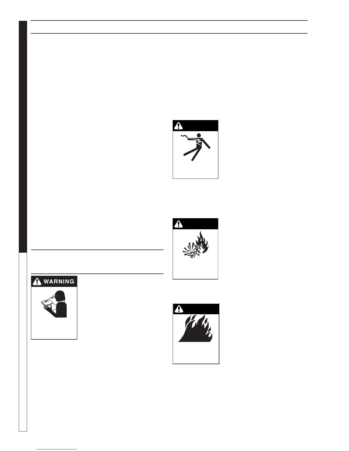
WARNING: To reduce the risk of
injury, read operating
instructions carefully before
using.
1. Readthe owner's
manual thoroughly. Failure
READ OPERATOR’S
PRIOR TO USE.
2. Know how to stop the machine and
bleed pressure quickly. Be thoroughly
familiar with the controls.
3. Stay alert — watch what you are doing.
4. All installations must comply with local codes.
Contact your electrician, plumber, utility company
or the selling distributor for specific details. If your
machine is rated 250 volts or less, single phase will
be provided with a ground fault circuit interrupter
(GFCI). If rated more than 250 volts, or more than
4
single phase this product should only be con-
to follow instructions could
cause malfunction of the
machine and result in death,
serious bodily injury and/or
property damage.
nected to a power supply receptacle protected by
a GFCI.
DANGER: Improper connection of the equipmentgrounding conductor can result in a risk of electrocution. Check with a qualified electrician or
service personnel if you are in doubt as to whether
the outlet is properly grounded. Do not modify the
plug provided with the product - if it will not fit the
outlet, have a proper outlet installed by a qualified
electrician. Do not use any type of adaptor with
this product
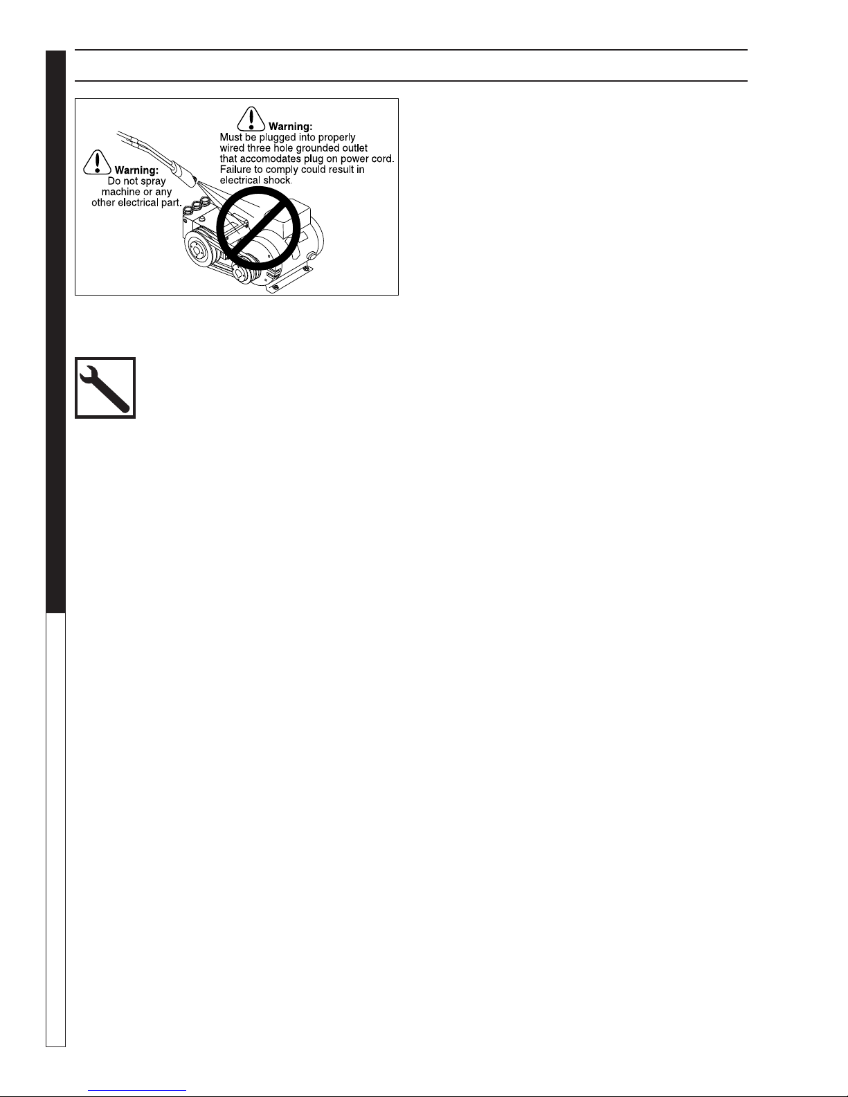
KEEP WATER
SPRAY AWAY FROM
ELECTRICAL WIRING.
to a UL grounded receptacle of proper voltage and
amperage ratings. Do not spray water on or near
electrical components. Do not touch machine with
wet hands or while standing in water. Always disconnect power before servicing.
RISK OF EXPLOSION:
OPERATE ONLY WHERE
IS PERMITTED
6. In oil burning models, use only kerosene, No. 1
home heating fuel, or diesel. If diesel is used, add
a soot remover to every tankful.
RISK OF FIRE.
DO NOT ADD FUEL
WHEN OPERATING
MACHINE.
7. Oil burning appliances shall be installed only in
locations where combustible dusts and flammable
gases or vapors are not present. Do not store or
use gasoline near this machine.
8. Do not allow acids, caustic or abrasive fluids to pass
through the pump.
9. Never run pump dry or leave spray gun closed
longer than 1-2 minutes.
Shark HPB • 9.801-190.0 • Rev. 7/13
WARNING: Keep wand, hose, and
water spray away from electric
wiring or fatal electric shock may
result.
5. To protect the operator from
electrical shock, the machine
must be electrically grounded.
It is the responsibility of the
owner to connect this machine
WARNING: Flammable liquids
can create fumes which can ignite, causing property damage
or severe injury.
WARNING: Risk of explosion —
Operate only where open flame
or torch is permitted.
WARNING: Risk of fire — Do not
add fuel when the product is
operating or still hot.
WARNING: Do not use gasoline
crankcase draining or oil containing gasoline, solvents or
alcohol. Doing so will result in
fire and/or explosion.
Page 5
WARNING
WARNING
IMPORTANT SAFETY INFORMATION
WARNING
WARNING
WARNING
WARNING
WARNING
WARNING
WARNING
PRESSURE WASHER
10. Keep operating area clear of all persons.
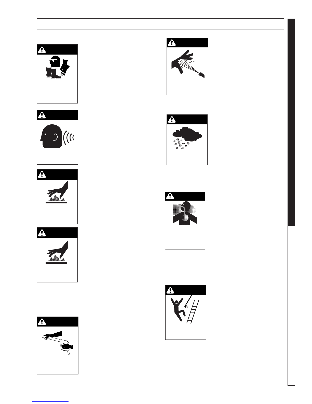
WARNING: High pressure spray
can cause paint chips or other
particles to become airborne
and fly at high speeds. To avoid
personal injury, eye, hand and
USE PROTECTIVE
EYE WEAR
AND CLOTHING
WHEN OPERATING
THIS EQUIPMENT.
foot safety devices must be
worn.
11. Eye, hand, and foot
protection must be worn
when using this equipment.
WARNING: This machine ex-
ceeds 85 db appropriate ear
protection must be worn.
EAR PROTECTION
MUST BE WORN
WARNING: Hot discharge fluid.
Do not touch or direct
discharge stream at persons.
WARNING: This machine produces hot water and must have
HOT DISCHARGE FLUID:
DO NOT TOUCH OR
DIRECT DISCHARGE
STREAM AT PERSONS.
insulated components attached
to protect the operator.
WARNING: Risk of injury. Hot
surfaces can cause burns. Use
only designated gripping areas
of spray gun and wand. Do not
place hands or feet on non-insulated areas of the pressure
RISK OF INJURY:
HOT SURFACES
CAN CAUSE BURNS
washer.
12. To reduce the risk of injury, close supervision is
necessary when a machine is used near children.
Do not allow children to operate the pressure
washer. This machine must be attended during
operation.
WARNING: Grip cleaning wand
securely with both hands before starting. Failure to do this
could result in injury from a
whipping wand.
13. Never make adjustments
TRIGGER GUN KICKS
BACK - HOLD WITH
BOTH HANDS
on machine while in
operation.
14. Be certain all quick coupler fittings are secured before using pressure washer.
Shark HPB • 9.801-190.0 • Rev. 7/13
WARNING: High pressure developed by these machines
will cause personal injury
or equipment damage. Keep
clear of nozzle. Use caution
when operating. Do not direct
RISK OF INJECTION
OR SEVERE INJURY
TO PERSONS. KEEP
CLEAR OF NOZZLE.
discharge stream at people,
or severe injury or death will
result.
WARNING: Protect machine from freezing.
15. To keep machine in best
operating conditions, it is
important you protect machine
from freezing. Failure to protect machine from freezing
could cause malfunction of the
machine and result in death,
PROTECT FROM
FREEZING
serious bodily injury, and/or
property damage. Follow storage instructions specified in this
manual.
16. Inlet water must be clean fresh water and no hotter
then 90°F.
WARNING: Risk of asphyxiation.
Use this product only in a well
ventilated area.
17. Avoid installing machines
in small areas or near exhaust fans. Adequate ox-
RISK OF
ASPHYXIATION: USE
THIS PRODUCT ONLY
IN A WELL
VENTILATED AREA.
ygen is needed for combustion or dangerous carbon monoxide will result.
18. Manufacturer will not be liable for any changes
made to our standard machines or any components not purchased from us.
19. The best insurance against an accident is precaution and knowledge of the machine.
WARNING: Be extremely careful
when using a ladder, scaffolding
or any other relatively unstable
location. The cleaning area
should have adequate slopes
and drainage to reduce the pos-
RISK OF INJURY
FROM FALLS WHEN
USING LADDER.
sibility of a fall due to slippery
surfaces.
20. Do not overreach or stand on unstable support.
Keep good footing and balance at all times.
OPERATOR’S MANUAL
5
Page 6
IMPORTANT SAFETY INFORMATION
PRESSURE WASHER
21. Do not operate this machine when fatigued or under
the influence of alcohol, prescription medications,
or drugs.
OPERATOR’S MANUAL
Follow the maintenance instructions
specified in the manual.
6
Shark HPB • 9.801-190.0 • Rev. 7/13
Page 7
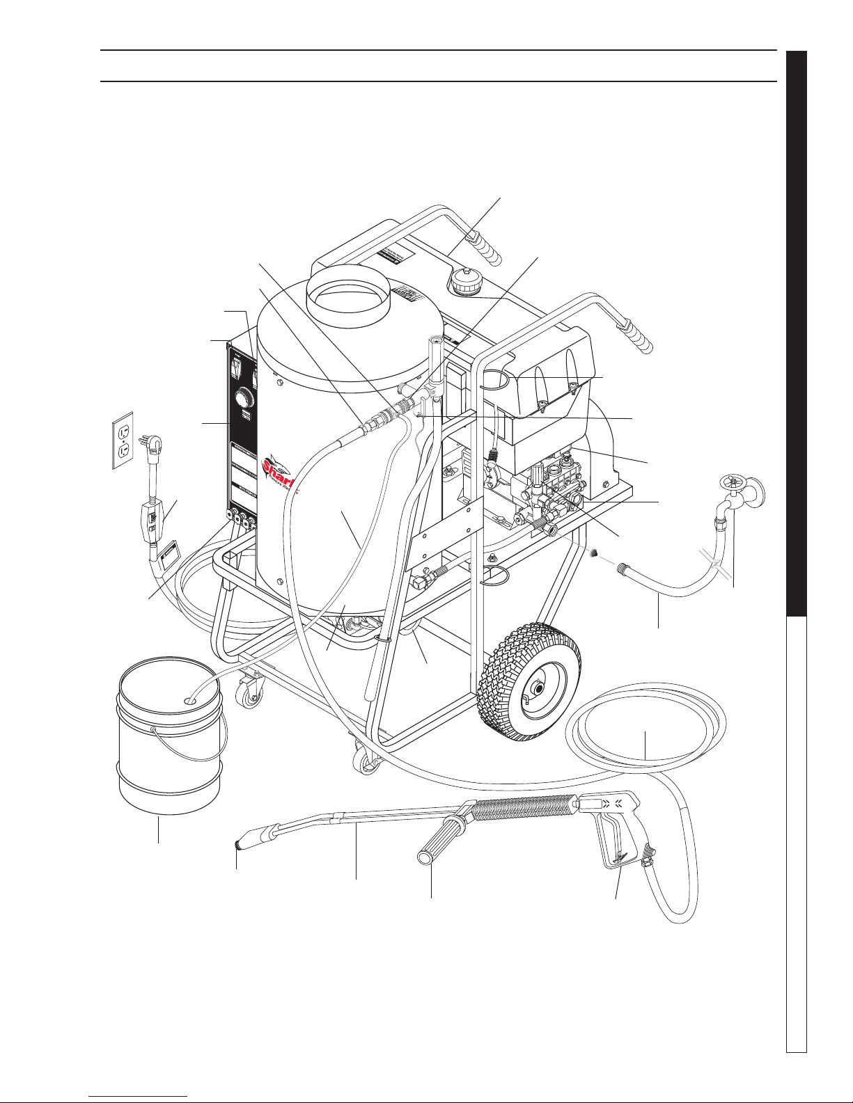
COMPONENT IDENTIFICATION
98011900-2
Fuel Tank
PRESSURE WASHER
CAUTION HOT WATER:
Must use insulated
spray gun and wand.
Burner Switch
Pump Switch
High
Pressure
Nozzle
Quick Coupler
Control
Panel
GFCI
Downstream
Detergent
Injector
Detergent
Pick-Up
Hose
Burner
Chamber
Burner
Motor
Discharge
Nipple
Wand Holder
High Limit
Thermostat
Pressure
Switch
Unloader
Garden Hose
(not included)
OPERATOR’S MANUAL
Pump
Fresh Water
Faucet
(not included)
Detergent
Bucket
(not included)
Nozzle
Coupler
Variable Pressure
Insulated Wand
Shark HPB • 9.801-190.0 • Rev. 7/13
Control
Handle
High Pressure
Hose
Insulated
Spray Gun
7
Page 8
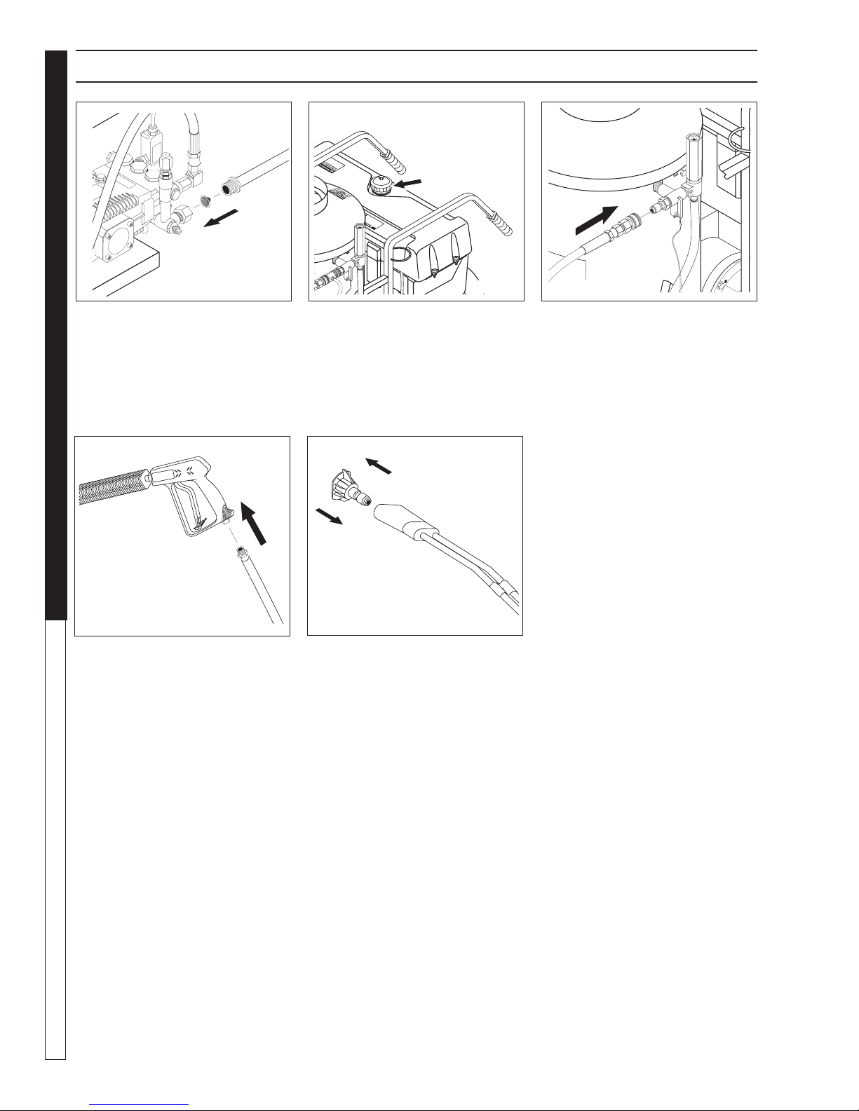
ASSEMBLY INSTRUCTIONS
98011900-3
98011900-4
98011900-5
98001190-5
Fuel
Cap
PRESSURE WASHER
STEP 1: Connect water supply
hose.
OPERATOR’S MANUAL
STEP 4: Attach the high pressure
hose to the spray gun using teflon
tape on hose threads.
STEP 2: Check fuel tank and
pump oil levels.
98001190-7
STEP 5: Connect the high pressure
hose to the pump discharge fitting.
Push coupler collar forward until
secure.
STEP 3: Connect high pressure
hose to discharge nipple by sliding
quick coupler collar back. Insert
quick coupler onto discharge nipple
and secure by pushing quick coupler
collar forward.
8
Shark HPB • 9.801-190.0 • Rev. 7/13
Page 9

INSTALLATION
PRESSURE WASHER
Place machine in a convenient location providing ample
support, draining and room for maintenance.
This machine is intended for outdoor use. Machine
must be stored indoors when not in use.
Location:
The location should protect the machine from damaging environmental conditions, such as wind, rain, and
freezing.
1. This machine should be run on a level surface
where it is not readily influenced by outside sources
such as strong winds, freezing temperatures, rain,
etc. It should be located to allow accessibility for
refilling of fuel, adjustments and maintenance. Normal precautions should be taken by the operator
of the machine to prevent moisture from reaching
the electrical controls.
2. It is recommended that a partition be made be-
tween the wash area and the machine to prevent
water spray from coming in contact with the machine. Excess moisture reaching any electric components or electrical controls will reduce machine
life and may cause electrical shorts.
3. During installation of the machine, beware of poorly
ventilated locations or areas where exhaust fans
may cause an insufficient supply of oxygen. Sufficient combustion can only be obtained when there
is a sufficient supply of oxygen available for the
amount of fuel being burned. If it is necessary to
install a machine in a poorly ventilated area, outside fresh air may have to be piped to the burner
and a fan installed to bring air into the machine.
Avoid small locations or areas near exhaust fans.
Electrical:
This machine, when installed, must be electrically
grounded in accordance to local codes. Check for
proper power supply using a volt meter.
Placement:
Do not locate near any combustible material. Keep all
flammable material at least 20 feet away.
Allow enough space for servicing the machine.
Local code will require certain distances from floor
and walls. (Two feet away from walls should be adequate.)
Water Source:
The water source for the pressure washer should be
supplied by a minimum 5/8" I.D. garden hose with a
city water pressure of not less than 30 PSI. If the water
supply is inadequate, or if the garden hose is kinked,
the attached pressure washer will run very rough and
the burner will not fire.
Connection:
Connect the wand, nozzle, hose and spray gun (where
applicable). On pipe thread connections, use teflon
tape to avoid water leaks. (See Component Identification).
Venting:
Adding exhaust vent pipe to your oil fired burner is
not recommended because restricted air flow causes
carbon build-up, which affects the operation, and increases maintenance on the coil. If a stack must be
used, refrain from using 90° bends. If the pipe can not
go straight up then use only 45° bends and go to the
next size pipe. The overall pipe length must not exceed
6 feet in length*.
*NOTE: After vent pipe installation test burner using
a smoke tester and adjust air setting to achieve a #3
or below results.
OPERATOR’S MANUAL
9
Shark HPB • 9.801-190.0 • Rev. 7/13
Page 10
98001190-9
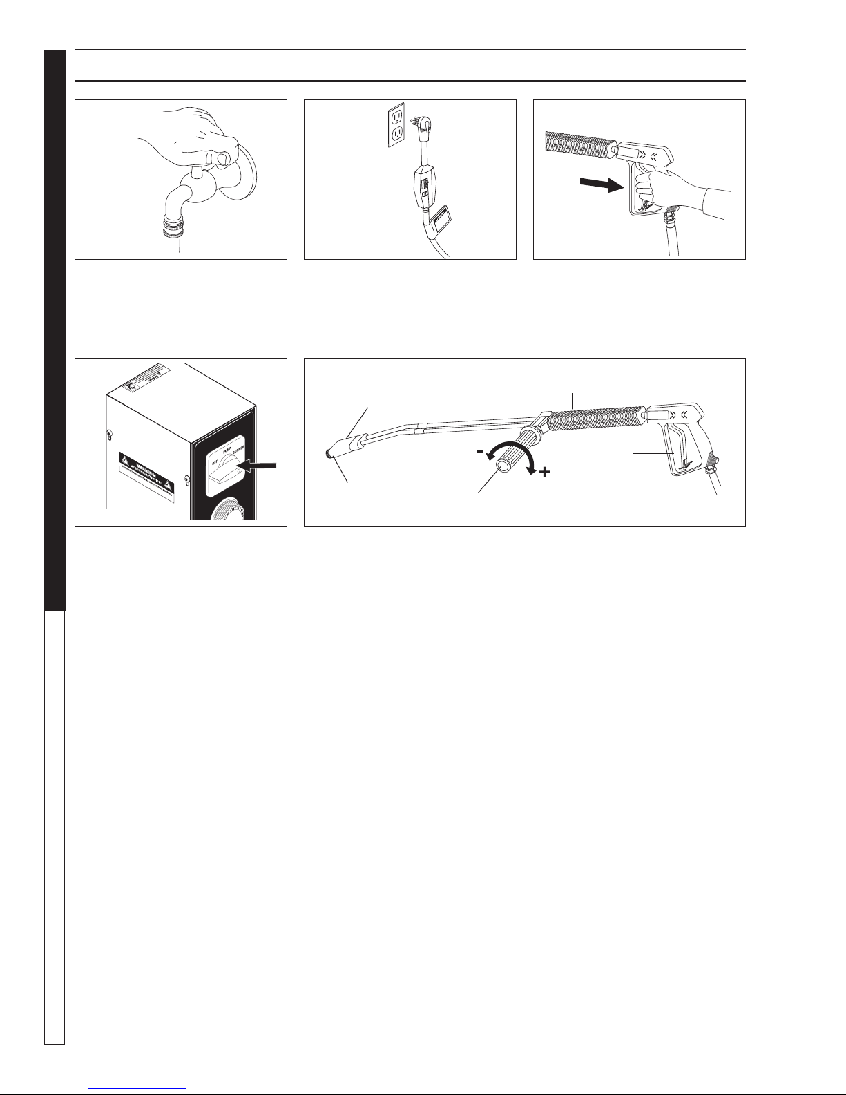
OPERATING INSTRUCTIONS
98001190-8
98001190-10
98001190-11
98001190-12
PRESSURE WASHER
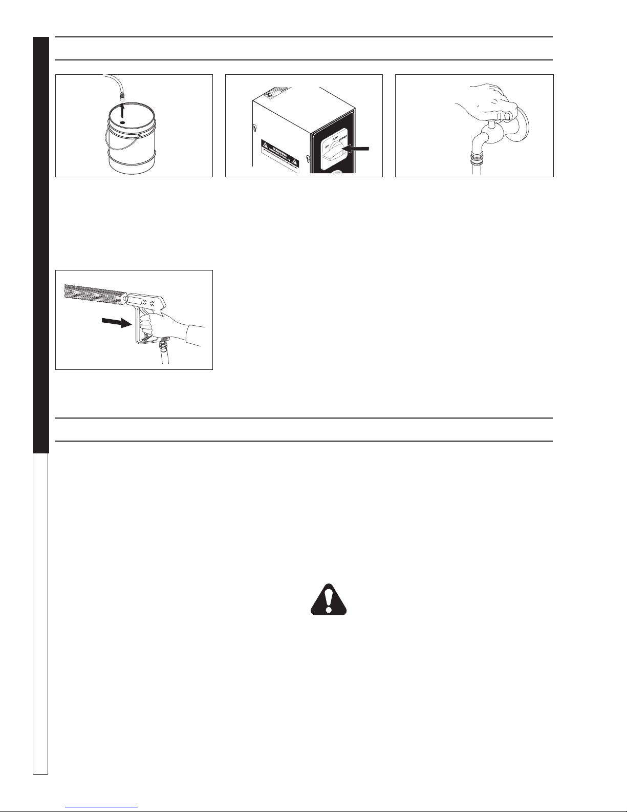
STEP 1: Turn water on. STEP 3: Grip spray gun handle
OPERATOR’S MANUAL
STEP 4: Before installing nozzle, turn on water supply and run
machine, allowing water to flush
STEP 2: Connect the power cord
into the proper electrical outlet, then
push in the GFCI reset button. (Refer to serial plate for information).
Brass Soap
Nozzle
High
Pressure
Nozzle
Variable Pressure
Control Handle
securely and pull trigger. Then turn
variable pressure control handle
counterclockwise.
Variable Pressure
Wand (VP)
Trigger
Selection of high or low pressure is accompanied by turning the handle.
NOTE: High pressure nozzle must be inserted at end of wand to obtain
high pressure. To apply soap read operator's manual.
through the system until clear.
Turn switch to pump position. When
a steady stream of water flows from
the spray gun and wand the machine is ready for cold water cleaning by turning the variable pressure
control handle clockwise to raise
the pressure.
For hot water washing, turn the
switch to the burner position. (The
burner will light automatically when
the trigger on the spray gun is
pulled.)
10
Shark HPB • 9.801-190.0 • Rev. 7/13
Page 11
WARNING
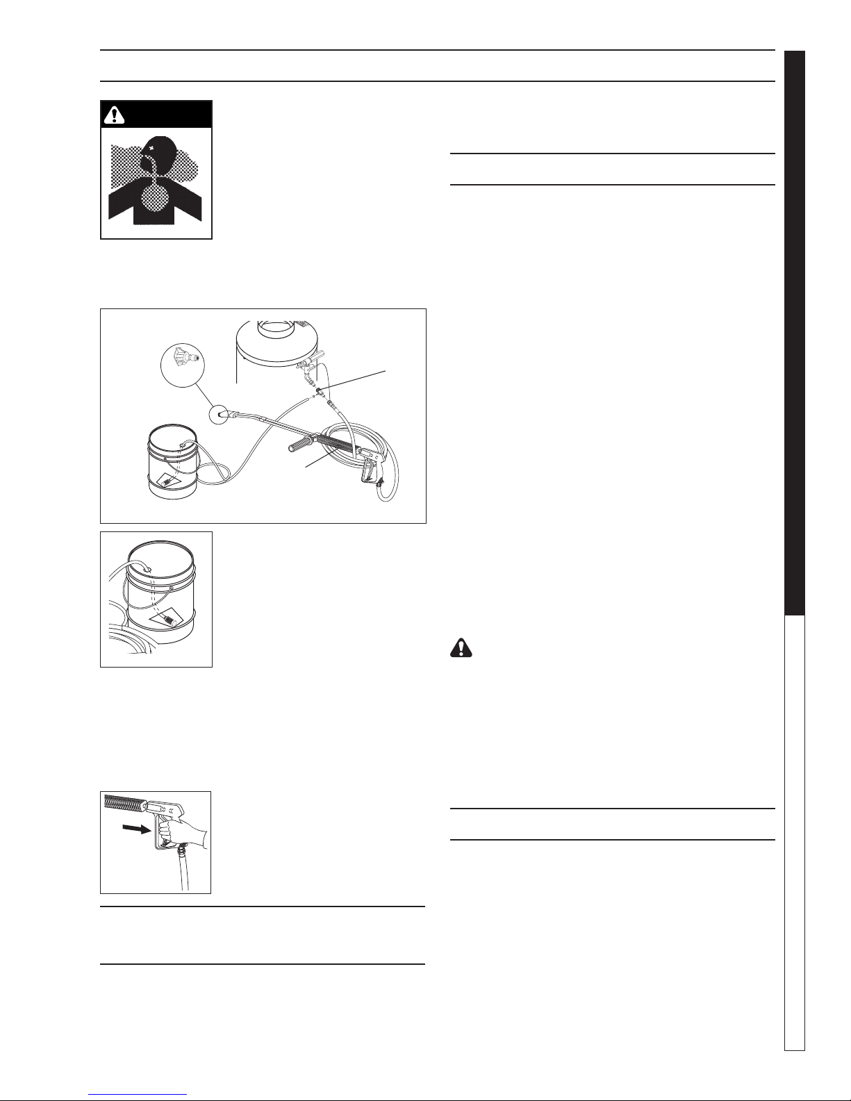
DETERGENTS & GENERAL OPERATING TECHNIQUES
98001190-15
9801190-13
PRESSURE WASHER
WARNING: Some detergents
may be harmful if inhaled or ingested, causing severe nausea,
fainting or poisoning. The harmful elements may cause property damage or severe injury.
STEP 1: Connect detergent injector to discharge nipple on
machine, Connect high pressure
hose to injector with quick coupler (check to make sure
locking coupler sleeves are in proper position before
applying water pressure.
High
Pressure
Hose
STEP 2: Use detergent designed
specifically for pressure washers. Household detergents could
damage the pump. Prepare detergent solution as required by the
manufacturer. Fill a container with
98001190-14
STEP 3: Apply safety latch to spray gun trigger. Turn
variable pressure control handle until discharge water
exits both tubes. Secure black detergent nozzle into
quick coupler if you have a single wand. NOTE: Detergent cannot be applied using Red, Yellow, Green
or White nozzles.
pressure washer detergent. Place
the filter end of detergent suction
tube into the detergent container.
STEP 4: With the engine running,
pull trigger to operate machine.
Liquid detergent is drawn into the
machine and mixed with water. Apply detergent to work area. Do not
allow detergent to dry on surface.
THERMAL PUMP
PROTECTION
If you run the engine on your pressure washer for
3-5 minutes without pressing the trigger on the spray
gun, circulating water in the pump can reach high temperatures. When the water reaches this temperature,
the pump protector engages and cools the pump by
discharging the warm water onto the ground. This
thermal device prevents internal damage to the pump.
Pre-rinse cleaning surface with fresh water. Place detergent suction tube directly into cleaning solution and
apply to surface at low pressure (for best results, limit
your work area to sections approximately 6 feet square
and always apply detergent from bottom to top). Allow
detergent to remain on surface 1-3 minutes. Do not
allow detergent to dry on surface. If surface appears
to be drying, simply wet down surface with fresh water.
If needed, use brush to remove stubborn dirt. Rinse at
Detergent
Injector
high pressure from top to bottom in an even sweeping
motion keeping the spray nozzle approximately 1 foot
from cleaning surface. Use overlapping strokes as you
clean and rinse any surface. For best surface cleaning
action spray at a slight angle.
Recommendations:
• Before cleaning any surface, an inconspicuous
area should be cleaned to test spray pattern and
distance for maximum cleaning results.
• Ifpaintedsurfacesarepeelingorchipping,use
extreme caution as pressure washer may remove the loose paint from the surface.
• Keepthespraynozzleasafedistancefromthe
surface you plan to clean. High pressure wash
a small area, then check the surface for damage. If no damage is found, continue to pressure
washing.
CAUTION - Never use:
• Bleach,chlorineandothercorrosivechemicals
• Liquids containing solvents(i.e.,paintthinner,
gasoline, oils)
• Tri-sodiumphosphateproducts
• Ammoniaproducts
• Acid-basedproducts
These chemicals will harm the machine and will damage the surface being cleaned.
It will take a few seconds for the detergent to clear.
Apply safety latch to spray gun. Remove black soap
nozzle from the quick coupler. Select and install the
desired high pressure nozzle. NOTE: You can also stop
detergent from flowing by simply removing detergent
siphon tube from bottle.
Shark HPB • 9.801-190.0 • Rev. 7/13
CLEANING TIPS
OPERATOR’S MANUAL
RINSING
11
Page 12
98001190-19
SHUTTING DOWN AND CLEAN-UP
98011900-16
98001190-17
98001190-18
PRESSURE WASHER
STEP 1: Remove detergent suction
tube from container and insert into
1 gallon of fresh water. Turn variable
pressure wand handle for low pressure or connect the black detergent
nozzle. Pull trigger on spray gun and
siphon water for one minute.
OPERATOR’S MANUAL
STEP 2: Turn burner switch off and
continue spraying water, allowing
the water to cool. After water has
cooled to less than 100°F, turn the
attached pressure washer off.
STEP 3: Turn off water supply.
STEP 4: Turn garden hose water
off. Open the spray gun to relieve
remaining pressure.
STORAGE
CAUTION: Always store your pressure washer in a
location where the temperature will not fall below
32°F (0°C). The pump in this machine is susceptible
to permanent damage if frozen. FREEZE DAMAGE
IS NOT COVERED BY WARRANTY.
1. Stop the pressure washer, squeeze spray gun trigger to release pressure.
2. Detach water supply hose and high pressure
hose.
3. Turn on the machine for a few seconds, until remaining water exits. Turn motor off immediately.
4. Drain the fuel from the fuel tank.
5. Do not allow high pressure hose to become
kinked.
6. Store the machine and accessories in a room which
does not reach freezing temperatures.
CAUTION: Failure to follow the above directions will
result in damage to your pressure washer.
When the pressure washer is not being operated or is
being stored for more than one month, follow these
instructions:
1. Replenish pump oil to upper level.
2. Drain fuel from fuel tank, fuel line and filter.
3. Cover the pressure washer and store in a clean, dry
place that is well ventilated away from open flame
or sparks.
After Extended Storage
CAUTION: Prior to restarting, thaw out any
possible ice from pressure washer hoses,
spray gun or wand.
12
Shark HPB • 9.801-190.0 • Rev. 7/13
Page 13

TROUBLESHOOTING
PROBLEM POSSIBLE CAUSE SOLUTION
LOW
OPERATING
PRESSURE
DETERGENT
NOT
DRAWING
PUMP RUNNING
NORMALLY BUT
PRESSURE LOW
ON INSTALLATION
FLUCTUATING
PRESSURE
PUMP
NOISY
Faulty pressure gauge Install new gauge.
Insufficient water supply Use larger garden hose; clean
filter washer at water inlet.
Old, worn or incorrect spray
nozzle
Plumbing or hose leak Check plumbing system for leaks.
Faulty or mis-adjusted unloader
valve (where applicable)
Worn packing in pump Install new packing kit.
Fouled or dirty inlet or discharge
valves in pump
Worn inlet or discharge valves Replace with valve kit.
Air leak Tighten all clamps.
Valve in the injector head may be
blocked, dirty or damaged
Filler screen on detergent suction
hose plugged
Dried up detergent plugging
metering valve
High viscosity of detergent Dilute detergent to specifications.
Hole in detergent line(s) Repair hole.
Low detergent level Add detergent if needed.
Discharge water temperature
above 180°F
Pump sucking air Check water supply and possibility of
Valves sticking Check and clean or replace if necessary.
Unloader valve seat faulty Check and replace if necessary.
Nozzle incorrectly sized Check and replace if necessary
Worn piston packing Check and replace in necessary.
Valves worn Check and replace if necessary.
Blockage in valve Check and replace if necessary.
Pump sucking air Check water supply and air
Worn piston packing Check and replace if necessary.
Air in suction line Check water supply and
Broken or weak inlet or discharge
valve springs
Excessive matter in valves Check and clean if necessary.
Worn bearings Check and replace if necessary.
Match nozzle number to machine
and/or replace with new nozzle.
Retape leaks with teflon tape.
Adjust unloader for proper pressure.
Install repair kit when needed.
Clean inlet or discharge valves.
Check detergent lines for holes.
Clean or replace valve in injector.
Clean or replace.
Disassemble and clean thoroughly.
Lower discharge water temperature.
air seepage.
(See serial plate for proper size).
seepage at joints in suction line.
connections on suction line.
Check and replace if necessary.
PRESSURE WASHER Troubleshooting Guide
13
Shark HPB • 9.801-190.0 • Rev. 7/13
Page 14

TROUBLESHOOTING
PROBLEM POSSIBLE CAUSE SOLUTION
LOW WATER
TEMPERATURE
WATER
TEMPERATURE
TOO HOT
PRESSURE WASHER Troubleshooting Guide
Improper fuel or water in fuel Drain fuel tank and replace with proper fuel.
Low fuel pressure Increase fuel pressure.
Weak fuel pump Check fuel pump temperature.
Replace pump if needed.
Fuel filter partially clogged Replace as needed.
Soot build up on coils Clean coils with soot remover.
Lime build up on coils Clean inside of coils using coil cleaner.
Improper burner nozzle See Burner Specifications.
Incoming water to machine
warm or hot
Fuel pump pressure too high Lower fuel pressure.
Fuel pump defective Replace fuel pump.
Detergent line sucking air Tighten all clamps. Check detergent line for holes.
Defective high limit switch
(thermostat)
Incorrect fuel nozzle size See Burner Specifications.
Insufficient water supplied Check GPM to machine.
Restricted water flow Check nozzle for obstruction, proper size.
Lower incoming water temperature.
Replace.
14
Shark HPB • 9.801-190.0 • Rev. 7/13
Page 15

MAINTENANCE CHARTS
This pressure washer was produced with the best available materials and quality craftsmanship. However, you
as the owner have certain responsibilities for the correct care of the equipment. Attention to regular preventative
maintenance procedures will assist in preserving the performance of your equipment. Contact your Pressure
Washers dealer for maintenance. Regular preventative maintenance will add many hours to the life of your pressure washer. Perform maintenance more often under severe conditions.
MAINTENANCE SCHEDULE
Replace Fuel Lines Annually
Pump Oil Inspect Daily inspect the oil level
Change After first 50 hours, then every 500 hours or annually
Clean Burner Filter Monthly (More often if fuel quality is poor)
Remove Burner Soot Annually
Burner Adjustment/Cleaning Annually
De-scale Coil Annually (More often if required)
Replace High Pressure Nozzle Every 6 months
Replace Quick Connects Annually
Clean Water Screen/Filter Weekly
Clean Float/Supply Tank Every 6 months
Replace HP Hose Annually if there is any sign of wear
Grease Motor Every 10,000 hours
Replace Burner Nozzle Annually
PRESSURE WASHER Troubleshooting Guide
Date Oil Changed
Month/Day/Year
OIL CHANGE RECORD
Estimated Operating
Hours Since Last
Oil Change
Shark HPB • 9.801-190.0 • Rev. 7/13
Date Oil Changed
Month/Day/Year
Estimated Operating
Hours Since Last
Oil Change
15
Page 16

PREVENTATIVE MAINTENANCE
1. Use clean fuel — kerosene, No. 1 home heating
fuel or diesel fuel. Clean or replace fuel filter every
100 hours of operation. Avoid water contaminated
fuel as it will seize up the fuel pump. De-soot coils
monthly. Use an additive if diesel is being used.
2. Check to see that the attached pressure washer
water pump is properly lubricated.
3. Follow winterizing instructions to prevent freeze
PRESSURE WASHER
damage to pump and coils.
4. Always neutralize and flush detergent from system
after use.
5. If water is known to be high in mineral content, use
a water softener on your water system, or de-scale
as needed.
6. Do not allow acidic, caustic or abrasive fluids to be
pumped through the system.
OPERATOR’S MANUAL
7. Always use high grade quality cleaning products.
8. Never run attached pressure washer pump dry for
extended periods of time.
9. If machine is operated with smoky or eye burning
exhaust, coils will soot up, preventing water from
reaching maximum operating temperature. (See
section on Maintenance and Service).
1 0. Never allow water to be sprayed on or near the
motor or burner assembly or any electrical component.
1 1. Delime coils as per instructions.
It is advisable, periodically, to visually inspect the
burner. Check air inlet to make sure it is not clogged
or blocked. Wipe off any oil spills and keep equipment
clean and dry.
The areas around the pressure washer should be kept
clean and free of combustible materials, gasoline and
other flammable vapors and liquids.
The flow of ventilating air to the burner must not be
blocked or obstructed in any manner.
MAINTENANCE AND SERVICE
Unloader Valves:
Unloader valves trap pressure in the line when a shutoff spray gun is closed. Machines with unloader valves
are preset and tested at the factory before shipping.
Tampering with the factory settings may cause personal injury and/or property damage and will void the
manufacturer's warranty.
Winterizing Procedure:
Damage due to freezing is not covered by warranty.
Adhere to the following cold weather procedures whenever the washer must be stored or operated outdoors
under freezing conditions.
During winter months, when temperatures drop below
32°F, protecting your machine against freezing is nec-
16
Shark HPB • 9.801-190.0 • Rev. 7/13
essary. Store the machine in a heated room. If this is
not possible then mix a 50/50 solution of anti-freeze/
water or windshield washer fluid with water in a 5 gallon bucket. Place a short section of garden hose into
the bucket and connect it to the machine. Elevate the
bucket and turn the pump on to siphon the anti-freeze
through the machine. If compressed air is available, an
air fitting can be screwed into the inlet connector and
by injecting compressed air, all water will be blown out
of the system.
If you have an optional float tank, pour the antifreeze
into this tank and run machine until antifreeze exits
discharge nipple.
High Limit Hot Water Thermostat:
For safety, each machine is equipped with a high limit
control switch. In the event the temperature of the water
should exceed its operating temperature, the high limit
control will turn the burner off until the water cools.
Pumps:
Use only SAE 30 weight non-detergent oil. Change oil
after first 50 hours of use. Thereafter, change oil every
three months or at 500 hour intervals. Oil level should
be checked by using the dipstick found on the top of
the pump or by the red dot visible through the oil gauge
window. Oil should be maintained at that level.
Cleaning of Coils:
In alkaline water areas, lime deposits can accumulate
rapidly inside the coil pipes. This growth is increased
by the extreme heat build up in the coil. The best
prevention for liming conditions is to use high quality
cleaning detergents. In areas where alkaline water is an
extreme problem, periodic use of deliming powder will
remove lime and other deposits before coil becomes
plugged.
Deliming Coils With A Pressure Washer:
Periodic flushing of coils is recommended.
Step 1 Fill a 5 gallon bucket with 4 gallons of water,
then add 1 lb. of deliming powder. Mix thoroughly.
Step 2 Remove the high pressure nozzle from the
pressure wand and put the wand into the
bucket. Secure the trigger on the spray gun
into the open position.
Step 3 Attach a short section (3-5 ft.) of garden hose
to the attached pressure washer to siphon solution from the elevated bucket. Start up pressure washer, allowing solution to be pumped
through pressure washer and into HPB coils
and back into the bucket. Solution should be
allowed to circulate 2-4 hours.
Page 17

MAINTENANCE
98011900-20
98011900-22
PRESSURE WASHER
Step 4 After circulating solution flush entire system
with fresh water.
Removal of Soot In Heating Coil:
In the heating process, fuel residue in the form of soot
deposits may develop between the heating coil pipe
and block air flow which will affect burner combustion.
When soot has been detected on visual observation,
the soot on the coil must be washed off after coil has
been removed using the following steps:
1. Remove the tank head assembly by unscrewing
the three tek screws and lifting the tank head off.
2. Remove the two pipe nipples and associated fit-
tings.
3. Lift the coil out of the outer wrap.
CAUTION: The coil weighs about 80 lbs. Use proper
lifting techniques.
4. Clean, repair and replace the coil by reversing the
above steps.
Coil Reinstallation
Reinstall by reversing the above steps 4 through 1.
Rupture Disk
If pressure from pump or thermal expansion should
exceed safe limits, the rupture disk will burst, allowing
high pressure to be discharged through hose to ground.
When the disk ruptures, it will need to be replaced.
Fuel:
Use clean fuel oil that is not contaminated with water
and debris. Replace fuel filter and drain tank every
100 hours of operation. Use Kerosene No. 1 or No.
2 Heating Fuel (ASTM D306) or diesel only. NEVER
use gasoline in your burner tank. Gasoline is more
combustible than fuel oil and could result in a serious
explosion. NEVER use crankcase or waste oil in your
burner. Fuel unit malfunction could result from contamination.
Ignition Circuit:
Periodically inspect wires, spring contact and electrodes for condition, security and proper spacing. For
transformer test (CAUTION 10,000 VOLTS) use
defect free insulated screwdriver and keep fingers off
blade! Lay blade across one contact: OK if arc will
span 1/2" between end of blade and other contact.
Electrode Setting
(See illustration below)
5/32" Gap
5/16"
Top View
Electrodes Check: Periodically check wiring connections.
If necessary to adjust electrodes, use diagram.
Electrode
Nozzles
1/16"
Side View
Burner Nozzle:
Keep the tip free of surface deposits by wiping it with
a clean, solvent-saturated cloth, being careful not to
plug or enlarge the nozzle. For maximum efficiency,
replace the nozzle each season.
Fuel Control System:
This machine utilizes a fuel solenoid valve located on
the fuel pump to control the flow of fuel to the combustion chamber. This solenoid is activated by a pressure
switch located on the unloader valve. When an operator releases the trigger on the spray gun, the pressure
drops, allowing the pressure switch to activate the fuel
solenoid. The solenoid then closes, shutting off the
supply of fuel to the combustion chamber. Controlling
the flow of fuel in this way gives an instantaneous burn
or no burn situation, thereby eliminating high and low
water temperatures, and combustion smoke normally
associated with machines incorporating a spray gun.
Periodic inspection is recommended to insure that the
fuel solenoid valve functions properly. This can be done
by operating the machine and checking to see that
when the trigger on the spray gun is in the off position,
the burner is not firing.
OPERATOR’S MANUAL
17
Shark HPB • 9.801-190.0 • Rev. 7/13
Page 18

MAINTENANCE
98011900-23
98011900-24
Fuel Pressure Adjustment:
To adjust fuel pressure, turn the adjusting screw with a
standard screwdriver (located on the fuel pump) clockwise to increase, counterclockwise to decrease.
Air Adjustment
The oil burner on this machine is preset for operation at
altitudes below 1000 ft. If operated at higher altitudes, it
PRESSURE WASHER
may be necessary to adjust the air band setting. Adjust
air band for a #1 or #2 smoke spot on the Bacharach
scale. If a smoky or eye-burning exhaust is being
emitted from the stack, two things should be checked.
First, check the fuel to be certain that kerosene or No.
1 home heating fuel is being used.
Next, check the air adjustment on the burner. An oily,
black, smoky fire indicates a lack of air and the air
OPERATOR’S MANUAL
band should be moved to allow the air to flow through
the burner. Sharp, eye-burning white fumes indicate
too much air flowing through the combustion chamber.
The air band should be moved to allow less air to flow
through the burner.
To adjust: start machine and turn burner ON. Loosen
the two locking screws found on the air band openings
(refer to illustrations) and close air band until black
smoke appears from burner exhaust vent. Note air
band position. Next, slowly open the air band until white
smoke just starts to appear. Turn air band halfway back
to the black smoke position previously noted. Tighten
locking screws.
FUEL AIR ADJUSTMENT: KNA
Air Band
Pressure
Gauge Port
Pressure
Fuel Pump
Adjustment
Screw
FUEL AIR ADJUSTMENT: BECKETT
Air Band
Transformer
18
Air Band
Adjustment
Screw
Shark HPB • 9.801-190.0 • Rev. 7/13
Fuel
Pump
Pressure
Gauge Port
Pressure
Adjustment Screw
Page 19

To Fuel
Filter
9801190-25
EXPLODED VIEW
PRESSURE WASHER
72
Detail See
Control Panel
16
51
31
For
Illus.
75
71
71
14
19
83
75
75, 26
68
79
26
73
30
71
50
49
21
53
1
27, 41, 71
8
15
61
54
50
78
10
49
30
6
57
56
58
55
For
Detail See
Pump
Illus.
OPERATOR’S MANUAL
9
2
67
32
33
3
42
28
88
63
60
86, 69
5
64
62
18, 29,
84, 87
4
25
66
47
65
70
48
45
46
59
37
23
22
69
12
69
81
40
74
For
Detail See
Optional
Float Tank
Illus.
76
77
77
80
7
39
11
For
Detail See
Steam Valve
Options
Illus.
To Fuel
Tank
16
38
52
24
48
51
13
85
36
35
34
20
43
17
44
82
Shark HPB • 9.801-190.0 • Rev. 7/13
19
Page 20

EXPLODED VIEW PARTS LIST
ITEM PART NO. DESCRIPTION QTY
1 8.932-960.0 Label, Diesel 1
2 9.800-006.0 Label, "Hot/Caliente"
with Arrows Warning 1
3 8.932-969.0 Label, Warning,
Service Cord 1
4 9.800-021.0 Label, Hot Water Outlet 1
5 8.900-870.0 Label, Shark 1
PRESSURE WASHER
6 9.800-035.0 Label, Warning (Lexan) 1
7 9.802-272.0 Wheel, 5" Caster 1
8 9.802-070.0 Grip, 1" Square, Handle 2
9 8.706-612.0 Tank, Fuel, 9 Gallon Poly,
Black 1
10 9.802-089.0 Cap, Fuel Tank,
Plastic H60-AV 1
OPERATOR’S MANUAL
11 9.800-020.0 Label, Cold Water Inlet 1
12 9.803-062.0 Frame Assy 1
13 9.802-225.0 Downstream Injector
Assembly, Non Adj. #3 1
14 9.803-064.0 Power Platform
(109.0) 1
9.803-063.0 Power Platform 1
15 9.802-107.0 Fastener, Ratchet,
Black Nylon 2
16 8.711-907.0 Wheel & Tire, 6.5" Steel Rim
12.5" Tire 2
17 8.750-094.0 Thermostat, 302° 1
18 For Motor, Please See Specifications Pages.
19 9.802-872.0 Tab, Belt Guard Mount 3
20 8.902-433.0 Valve, Safety Relief 1
21 8.932-965.0 Label, Warning,
Exposed Pulley 1
22 9.802-792.0 Nut, Cage, 3/8" x 12 Gauge 4
23 9.802-905.0 Insulation Blanket,
18" OD x 4.5" ID 1
24 9.802-013.0 Nipple, 1/2" x 2-1/2" 1
25 9.802-775.0 Nut, 1/4", Flange 4
26 9.802-720.0 Bolt, 3/8" x 1" 6
(109.0,) 8
27 9.802-733.0 Bolt, 3/8" x 3-1/2", Tap 2
28 9.802-995.0 Coil, 18" 1
9.802-897.0 Insulation Blanket 1
29 9.802-518.0 Strain Relief, 3/4" (109.0) 1
9.803-279.0 Strain Relief, 1"
(110.0,111.0,112.0) 1
30 9.802-803.0 Washer, 1/4" 4
31 8.933-031.0 Outer Wrap, 18" Coil S.S. 1
32 9.802-973.0 Tank End 18" 1
33 8.717-442.0 Insulation Disk 1
34 8.706-248.0 Plug, 3/8" 1
ITEM PART NO. DESCRIPTION QTY
35 9.802-171.0 Nipple, 3/8" x 3/8" NPT Street
Male 1
36 9.149-003.0 Manifold Coil Discharge 1
37 9.802-043.0 Elbow, 1/2" JIC x 1/2"
Female 1
38 8.918-423.0 Hose, 3/8" x 22" 1
39 8.706-958.0 Hose Barb, 1/4" Barb,
1/4" Pipe, 90° 1
40 9.802-273.0 Wheel, 5" Caster, w/Brake 1
41 9.802-789.0 Nut, 3/8" Hex 2
42 8.719-935.0 Retainer Ring, Insulation 1
43 9.196-012.0 Screw, 10-24 x 1/4" 1
44 8.711-785.0 Hose, 3/8" Push-On 30"
45 8.725-306.0 Filter, Fuel/H
46 9.802-781.0 Nut, 3/8" Flange, Whiz Loc 4
47 9.803-264.0 Nipple, 1/4" x 3", Black Pipe 1
48 9.802-810.0 Washer, 5/8" Flat 2
49 9.802-770.0 Screw, 1/4" x 1" 7
50 9.802-094.0 Belt Guard 1
51 9.802-782.0 Collar, 5/8" 2
52 9.803-066.0 Axle, SR 1
53 9.803-131.0 Pump Rail, Black 1
54 For Pulley, Please See Specifications Pages.
55 For Pulley, Please See Specifications Pages.
56 For Belt, Please See Specifications Pages.
57 For Bushing, Please See Specifications Pages.
58 9.802-402.0 Bushing, 24mm 1
59 For Burner, Please See Specifications Pages.
60 9.802-825.0 Clip, Retainer 4
61 9.800-046.0 Label, Belt Guard 1
62 9.803-030.0 Retainer, Burner Insulation 1
63 9.802-768.0 Screw, 3/8" x 1-1/4" Whiz Loc 4
64 9.802-014.0 Nipple, 1/2" x 3", Galvanized 1
65 8.718-618.0 Bolt, 5/16" x 3/4" 1
66 8.718-980.0 Washer, 5/16 Flat
67 9.802-794.0 Nut, Cage, 1/4" x 12 Gauge 6
68 9.802-754.0 Screw, 1/4" x 1/2", Whiz Loc 3
69 9.802-752.0 Screw, 1/4" x 1-1/4",
Whiz Loc 8
70 8.718-817.0 Nut, 1/4-20 Whiz Loc 8
71 9.802-807.0 Washer, 3/8", Flat
(109.0) 25
23
72 9.802-430.0 GFCI, 230V, 30 Amp (109.0) 1
9.802-434.0 GFCI, 240V, 40 Amp (110.0) 1
9.802-437.0 Service Cord, 10/4 (111.0 ) 15 ft.
9.802-429.0 Service Cord, 12/4 (112.0 ) 15 ft.
O 1
2
4
20
Shark HPB • 9.801-190.0 • Rev. 7/13
Page 21

EXPLODED VIEW PARTS LIST
ITEM PART NO. DESCRIPTION QTY
73 8.920-445.0 Adapter Plate, Pump 1
74 8.706-941.0 Hose Barb, 1/4" 1
75 9.802-779.0 Nut, 3/8" ESNA 11
76 9.802-254.0 Fuel Line, 1/4" 28"
77 6.390-126.0 Clamp, Hose, .46-, .54 4
78 9.802-775.0 Nut 1/4" Flange ZN 2
79 9.804-082.0 Washer, 1/4" Flat Zinc 2
80 9.802-254.0 Fuel Line, 1/4" 28"
81 9.802-448.0 Conduit, Water Tite 2.25 ft.
82 9.802-517.0 Connector 1/2" L/T 90° Black 1
83 9.802-765.0 Screw, 1/4-20 x 1/2" BH Black 2
84 9.802-436.0 Cord Service 10-3 (109.0) 41"
9.802-437.0 Cord Service 10-4 (111.0) 41"
9.802-425.0 Cord Service 8-3 (110.0) 41"
85 8.706-141.0 Coupling, 1/2" x Steel Pipe 1
86 9.802-793.0 Nut, Cage 1/4" x 16 Gauge 4
87 9.802-526.0 Lock Nut 3/4" (109.0) 1
9.803-280.0 Lock Nut 1" (110.0,
111.0,112.0) 1
88 9.802-778.0 Nut, Whiz 5/16 Flange 4
Not Shown
PRESSURE WASHER
OPERATOR’S MANUAL
21
Shark HPB • 9.801-190.0 • Rev. 7/13
Page 22

8
10
12
14
16
0
2
4
6
GROU
ND
CONTROL PANEL EXPLODED VIEW
PRESSURE WASHER
OPERATOR’S MANUAL
14
13
34
32
17
13
2, 8
2
35, 36
1
27
24
25
21
7
15
1
33
38
19
20
32
16
17
31
30
16
17
9
39
37
17
22
23
17
18
28
12
26
6
3
4
13
CONTROL PANEL PARTS LIST
ITEM PART NO. DESCRIPTION QTY
1 9.802-451.0 Switch, Rocker,
Carling w/Green Lens 2
(Time Delay Option) 1
9.802-452.0 Rocker Switch, Red Lens
(Time Delay Option) 1
2 9.802-447.0 Conduit, 1/4" Split 48"
3 For Fuse, Please See Specifications Pages.
4 For Fuse, Please See Specifications Pages.
5 For Transformer,
Please See Specifications Pages.
6 For Contactor,
Please see specifications pages.
7 9.802-518.0 Strain Relief, Straight, L/T 1
9.802-521.0 Strain Relief, 3/4" Watertight
(110.0) 1
22
Shark HPB • 9.801-190.0 • Rev. 7/13
11
10
5
ITEM PART NO. DESCRIPTION QTY
8 8.750-095.0 Thermostat, 302° 1
9 9.802-283.0 Hour Meter (Optional) 1
10 8.712-357.0 Nozzle, SAQCMEG 0055,
Red (109.0) 1
8.712-358.0 Nozzle, SAQCMEG 1505.5,
Yellow (109.0) 1
8.712-359.0 Nozzle, SAQCMEG 2505.5,
Green (109.0) 1
8.712-360.0 Nozzle, SAQCMEG 4005.5,
White (109.0) 1
8.712-345.0 Nozzle, SAQCMEG 0004,
Red (110.0,111.0,112.0) 1
8.712-346.0 Nozzle SAQCMEG 1504,
Yellow (110.0,111.0,112.0) 1
8.712-347.0 Nozzle, SAQCMEG 2504,
Green (110.0,111.0,112.0) 1
8.712-348.0 Nozzle, SAQCMEG 4004,
White (110.0,111.0,112.0) 1
Page 23

CONTROL PANEL PARTS LIST
PRESSURE WASHER
ITEM PART NO. DESCRIPTION QTY
11 9.802-064.0 Grommet, Rubber, Nozzle
Holder 4
12 9.802-880.0 Cover, Electrical Box 1
13 9.802-759.0 Screw, 10/32" x 1/2" 13
(Time Delay Option) 2
14 9.800-016.0 Label, Disconnect
Power Supply 1
15 9.802-791.0 Nut, Cage,
10/32" x 16 Gauge 6
16 9.802-762.0 Screw, 10/32" x 1-1/4" 1
(Auto Start/Stop Option) 1
17 9.802-695.0 Nut, 10/32" Keps 4
(Auto Start/Stop
Delay Option) 1
(Time Delay Option) 2
18 9.800-112.0 Label, Control Panel 1
19 9.800-040.0 Label, Ground 1
20 9.802-517.0 Connector, 1/2",
L/T 90°, Black 1
21 9.802-514.0 Strain Relief, Straight,
L/T, Small 1
22 9.802-526.0 Locknut, 3/4" 1
23 9.802-525.0 Locknut, 1/2" 1
24 9.802-103.0 Bushing, Snap, 5/8" 1
25 9.802-518.0 Strain Relief, Straight,
L/T, Large 1
26 9.800-018.0 Label, Tipover Hazard 1
27 9.800-049.0 Label, Cleaning Solution 1
28 9.802-526.0 Lock Nut 3/4" (All Models) 1
29 9.802-457.0 Din Rail 4"
(Time Delay Option) 2"
30 9.802-491.0 Block Terminal 4 Pole
(Auto Start/Stop, Time
Delay Option) 1
31 9.802-472.0 Timer Solid State 120V, 5-60,
Minute Adj. (Auto Start/Stop
Option) 1
32 9.802-749.0 Screw 8/32" x 3/4"
(Auto Start/Stop,
Time Delay Option) 2
33 9.802-785.0 Nut 8/32" Keps
(Auto Start/Stop,
Time Delay Option) 2
ITEM PART NO. DESCRIPTION QTY
34 8.751-306.0 Timer, Multi Function
24V-120/240V
(Time Delay Option) 1
35 9.802-467.0 Base Relay
(Time Delay Option) 1
36 9.802-468.0 Relay 120V
(TimeDelay Option) 1
37 8.750-096.0 Knob, Themostat 302°F 1
38 8.712-190.0 Bezel, Plastic 1
39 9.196.012.0 Screw, 10/24 x 1/4" Hex 2
Not Shown
OPERATOR’S MANUAL
23
Shark HPB • 9.801-190.0 • Rev. 7/13
Page 24

34
21
FLOAT TANK OPTION EXPLODED VIEW
30
32
38
31
33
4
16
15
14
21
30
PRESSURE WASHER
18
OPERATOR’S MANUAL
98011900-27
22
39
42
Steam Option
20
21
22
23
48
47
21
19
20
23
36
13
47
46
To Float
Tank
18
53
35
17
18
19
4
51
49
50
50
44
45
7
27
7
43
11
9
Auto Start/Stop
24
1, 8
2
5
33
10
Option
13
28
21
34
54
29
39
11
12
41
40
26
6
4
3
21
35
48
47
19
20
22
23
10
13
7
27
25
36
47
53
46
45
18
27
7
To Float Tank
37
4
9
7
39
38
21
49
31
32
33
50
43
10
9
7
Auto Start/Stop
Steam Option
ITEM PART NO. DESCRIPTION QTY
1 8.706-645.0 Tank, Float 1
2 9.803-269.0 Shelf, Float Tank, Black 1
3 9.802-767.0 Screw, 3/8" x 3/4"
HH NC, Whiz Loc 4
4 9.802-039.0 Elbow, 1/2" JIC x 3/8"
Female, 90° 1
5 9.803-277.0 Screw, 5/16" x 1/2"
Whiz Loc 4
6 9.802-259.0 Hose, 1/2", Push-On 20"
7 9.802-201.0 Clamp, Screw, #6 3
8 8.932-994.0 Valve, Float 1
24
ITEM PART NO. DESCRIPTION QTY
9.802-062.0 Ball Float 1
9 8.706-943.0 Hose Barb, 5/8" Barb x 1/2"
ML Pipe 1
10 8.706-820.0 Elbow, 1/2" Female, Brass 1
11 9.802-111.0 Nipple, 1/2" NPT, 5/16",
Modified Close 1
12 9.802-043.0 Elbow, 1/2" x 1/2" Female, 90° 1
13 8.918-423.0 Hose, 3/8" x 22", 2 Wire,
Pressure Loop 1
14 9.802-146.0 Swivel, 1/2" MP x 3/4"
GHF w/Strainer 1
Shark HPB • 9.801-190.0 • Rev. 7/13
Page 25

FLOAT TANK PARTS LIST
PRESSURE WASHER
ITEM PART NO. DESCRIPTION QTY
15 9.802-961.0 Hose Connection Bracket 1
16 9.802-700.0 Bolt, 1/4" x 3/4", NC HH 2
17 9.802-781.0 Nut, 3/8", Flange,
Whiz Loc, NC 4
18 8.706-780.0 Nipple, 1/4" Hex 1
19 8.707-317.0 Valve, Flow Control 1
20 8.706-941.0 Hose Barb, 1/4" Barb x 1/4"
ML Pipe 1
21 6.390-126.0 Clamp, Hose, .46-, .54 ST 1
(Float Tank w/Steam) 3
22 9.802-251.0 Tube, 1/4" x 1/2",
Clear Vinyl 72"
23 8.707-058.0 Strainer, 1/4" Brass
w/Check Valve 1
24 9.802-087.0 Cover, Float Tank,
Portotenica 1
25 9.802-131.0 Elbow, 1/2" JIC x 1/2", 90° 1
26 9.802-151.0 Swivel, 1/2" JIC Female,
Push-On 1
27 9.802-260.0 Hose, 5/8" Push-On 12"
28 9.802-773.0 Nut, 1/4", ESNA, NC 2
29 9.802-802.0 Washer, 1/4" Flat, SAE 4
30 8.706-958.0 Hose Barb, 1/4" Barb x 1/4"
Pipe, 90° 1
31 9.802-187.0 Valve, Flow Control
w/Metering 1
32 8.705-973.0 Nipple, 1/4" Hex Steel 1
33 9.802-632.0 Cap, Valve w/ 1/4"
Gauge Port 1
34 9.802-254.0 Hose, 1/4", Push-on 14"
35 8.933-006.0 Switch, MV60 Flow 1
36 8.706-168.0 Elbow, 3/8" Male Pipe 1
37 9.804-555.0 Cross, 1/2" Female
w/ 1/4"-20 Hole 1
38 9.800-026.0 Label, Open For Steam 1
39 8.706-997.0 Adapter 1/4" x 1/8" 1
40 9.804-554.0 Screw, 10/32" x 2-1/2" 1
41 9.802-695.0 Nut, 10/32" Keps 1
42 8.706-855.0 Tee, 1/4" Street 1
43 8.706-797.0 Nipple, 1/2" Hex 1
44 9.802-119.0 Cross, 1/2" Female 1
45 8.706-915.0 Bushing, 1/2" x 1/4" 1
ITEM PART NO. DESCRIPTION QTY
46 9.802-128.0 Nipple, 1/2" JIC x 1/2" Pipe 1
47 9.802-151.0 Swivel, 1/2" JIC Female,
Push-On 2
48 9.802-259.0 Hose, 1/2", Push-On 16"
49 9.802-129.0 Elbow, 1/2" JIC x 3/8" 90° 1
50 9.802-362.0 Unloader VB8 w/Switch 1
51 9.802-458.0 Switch, Pressure N/O 1/4",
NPT SS 1
52 8.706-207.0 Elbow, 3/8" Street 1
53 8.706-309.0 Adapter, 3/8" x 3/8" Street 1
54 8.706-940.0 Hose Barb, 1/4" Barb x 1/8"
ML Pipe 1
Not Shown
OPERATOR’S MANUAL
25
Shark HPB • 9.801-190.0 • Rev. 7/13
Page 26

6
PRESSURE WASHER
AUTO START/STOP OPTIONS EXPLODED VIEW
7
8
13
16
9
15
12
OPERATOR’S MANUAL
98011900-28
5
5
AUTO START/STOP OPTIONS PARTS LIST
ITEM PART NO. DESCRIPTION QTY
1 9.802-146.0 Swivel, 1/2" MP x 3/4" GHF
w/Strainer 1
2 8.706-844.0 Tee, 1/2" Female Pipe 1
3 8.706-797.0 Nipple, 1/2" Hex 1
4 9.802-127.0 Nipple, 1/2" JIC x 1/2" MPT
Pipe 1
5 9.802-151.0 Swivel, 1/2" JIC Fem,
Push-on 2
6 9.802-259.0 Hose, 1/2" Push-on 16"
7 9.802-039.0 Elbow, 1/2" JIC, 3/8" 1
8 9.802-129.0 Elbow, 1/2" JIC x 3/8" 1
9 9.802-362.0 Unloader, VB8 w/Switch 1
10 Pump, Please See Specifications Pages
11 8.707-256.0 Pump Protector, 1/2" 1
11
14
10
4
2
3
1
ITEM PART NO. DESCRIPTION QTY
12 9.802-632.0 Cap, Valve with 1/4" Ga Port 1
13 9.802-458.0 Switch, Pressure 1/4" NPT 1
14 8.706-207.0 Elbow, 3/8" Street 1
15 8.706-309.0 Adapter, 3/8" x 3/8" Street 1
16 8.918-423.0 Hose, 3/8" x 22", Pressure
Loop 1
26
Shark HPB • 9.801-190.0 • Rev. 7/13
Page 27

AUTO START/STOP - STEAM OPTIONS EXPLODED VIEW
10
12
21
11
1
23
8
22
OPEN
FOR
20
STEAM
10-99011
19
9
18
PRESSURE WASHER
OPERATOR’S MANUAL
6
7
22
5
6
AUTO START/STOP - STEAM OPTIONS PARTS LIST
ITEM PART NO. DESCRIPTION QTY
1 8.918-423.0 Hose, 3/8" x 22"
Pressure Loop 1
2 9.802-146.0 Swivel, 1/2 x 3/4 GHF
w/Strainer 1
3 9.802-123.0 Tee, 1/2" w/1/8" Hole Street 1
4 9.802-131.0 Elbow, 1/2" JIC x 1/2 - 90° 1
5 9.802-142.0 Hose Barb, 1/4 Barb x 1/8"
Pipe 90°1
6 9.802-151.0 Swivel, 1/2" JIC Fem,
Push-on 2
7 9.802-259.0 Hose, 1/2" Push-on 16"
8 9.802-129.0 Elbow, 1/2 JIC x 3/8" 90° 1
9 9.802-362.0 Unloader, VB8 w/Switch 1
10 9.803-044.0 Elbow, 3/8" Male Pipe 1
11 9.802-459.0 Switch, Flow 1
12 9.802-039.0 Elbow, 1/2 JIC, 3/8" 1
13 8.706-207.0 Elbow, 3/8" Street 1
17
14
13
3
4
2
16
15
98011900-29
ITEM PART NO. DESCRIPTION QTY
14 8.706-309.0 Adapter, 3/8" x 3/8" Steel 1
15 8.707-256.0 Pump Protector 1/2" 1
16 For Pump, Please See Specifications Pages
17 9.804-022.0 Cap, Valve w/1/4" Ga. Port 1
18 9.802-010.0 Nipple, 1/4" Hex Steel 1
19 9.802-187.0 Valve, Flow Control
w/Metering 1
20 9.802-026.0 Label, Open for Steam 1
21 9.802-143.0 Hose Barb, 1/4"
Barb x 1/4" Pipe 1
22 6.390-126.0 Clamp, Hose 2
23 9.802-254.0 Hose, 1/4" Push-on 14"
27
Shark HPB • 9.801-190.0 • Rev. 7/13
Page 28

PUMP ASSEMBLY EXPLODED VIEW
98011900-30
2
PRESSURE WASHER
OPERATOR’S MANUAL
7
1
6
3
8
5
4
28
PUMP ASSEMBLY PARTS LIST
ITEM PART NO. DESCRIPTION QTY
1 8.707-256.0 Pump Protector, 1/2" 1
2 9.802-458.0 Pressure Switch, 1/4" 1
3 9.802-039.0 Elbow, 1/2" JIC x 3/8", 90° 1
4 9.802-146.0 Swivel, 1/2" GHF 1
5 For Unloader, Please See Specifications Pages
6 For Pump, Please See Specifications Pages
7 9.802-632.0 Cap, Valve w/1/4" Port 1
8 8.706-864.0 Plug, 1/8" Countersunk 1
Shark HPB • 9.801-190.0 • Rev. 7/13
Page 29

STEAM OPTIONS EXPLODED VIEW
1
2
10
3
8
11
4
5
15
12
PRESSURE WASHER
OPERATOR’S MANUAL
9
2
7
14
STEAM OPTIONS PARTS LIST
ITEM PART NO. DESCRIPTION QTY
1 9.802-143.0 Hose Barb, 1/4" Barb x 1/4"
Pipe, 90° 2
2 6.390-126.0 Clamp, Hose, .46-, .54 ST 2
3 9.802-187.0 Valve, Flow Control
w/Metering 1
4 9.802-010.0 Nipple, 1/4" Hex Steel 1
5 9.802-632.0 Cap, Valve with 1/4"
Gauge Port 2
6 9.802-459.0 Switch, MV-60 Flow 1
7 9.802-146.0 Swivel, 1/2" MP x 3/4"
GHF w/Strainer 1
6
13
98011900-31
ITEM PART NO. DESCRIPTION QTY
8 For Unloader, Please See Specifications Pages.
9 For Pump, Please See Specifications Pages.
10 9.800-026.0 Label, Open For Steam 1
11 9.802-254.0 Hose, 1/4" Push-On 14"
12 9.802-039.0 Elbow, 1/2" JIC x 3/8" 1
13 9.803-044.0 Elbow, 3/8" Pipe, Male 1
14 9.802-142.0 Hose barb 1/4",
Barb x 1/8" Pipe 90° 1
15 8.707-256.0 Pump Protector, 1/2" 2
29
Shark HPB • 9.801-190.0 • Rev. 7/13
Page 30

98011900-32
HOSE & SPRAY GUN ASSEMBLY EXPLODED VIEW
6
8
PRESSURE WASHER
1
OPERATOR’S MANUAL
9
10
2
Pressure Nozzle
3
5
7
4
HOSE & SPRAY GUN ASSEMBLY PARTS LIST
ITEM PART NO. DESCRIPTION QTY
1 9.802-165.0 Coupler, 1/4" Male 1
9.802-096.0 Quick Coupler O-Ring,
Small 1
2 9.802-286.0 Nozzle Only, 1/8" Soap 1
3 9.802-222.0 Wand, Zinc, VP,
w/Coupler 1
4 8.739-125.0 Hose, 3/8" x 50' 1 Wire,
Tuff-Flex 1
5 8.710-384.0 Gun, ST-1500, 5000 PSI
10.4 GPM 1
6 9.802-225.0 Detergent Injector,
Non Adjust #3 (109.0,
110.0, 111.0, 112.0) 1
30
Shark HPB • 9.801-190.0 • Rev. 7/13
ITEM PART NO. DESCRIPTION QTY
7 9.802-160.0 Strainer, 1/4" Hose Barb 1
8 9.802-166.0 Coupler, 3/8" Female 1
9.802-100.0 Quick Coupler,
O-Ring, Large 1
9 6.390-126.0 Clamp, Hose, .46-, .54 ST 2
10 9.802-251.0 Tube, 1/4" x 1/2"
Clear Vinyl 6 ft.
Not Shown
Page 31

UU1 UNLOADER VALVE EXPLODED VIEW
9.175-018.0, 3500 PSI
Universal Unloader
PRESSURE WASHER
OPERATOR’S MANUAL
UU1 UNLOADER VALVE EXPLODED VIEW PARTS LIST
ITEM PART # DESCRIPTION KIT QTY
1 Piston Housing A 1
2 Piston C 1
3 8.749-795.0 Piston O-Ring Back up 1
4 8.749-796.0 Main Block 1
5 9.152-372.0 Piston Ring 1
6 Ball Seat C 1
7 O-Ring, 10.5 ID x 1.5 CS A,C 1
8 Plunger B 1
9 9.152-016.0 Plunger Housing 1
10 Bypass Spring C 1
11 9.149-001.0 Low Pressure Port 1
12 9.152-017.0 Sliding Connector, 30 mm 1
8.762-005.0 Sliding Connector, 40 mm 1
13 9.149-002.0 Sliding Connector H 1/2" 1
9.149-005.0 Sliding Connector H 3/8" 1
14 9.196-011.0 Plug, 5/8 - 18 UNF 1
15 O-Ring 12 ID x 2 CS A 2
16 O-Ring 6 ID x 2 CS A 1
Shark HPB • 9.801-190.0 • Rev. 7/13
ITEM PART # DESCRIPTION KIT QTY
17 9.149-006.0 Sliding Connector Guide 1
18 O-Ring Back up A 1
19 Conical Seal C 1
20 O-Ring 6.75 x 1.78 BN80 A 1
21 Spring Seat C 1
22 Plunger Spring B 1
23 8.762-001.0 Banjo Bolt, 1/2" 1
8.762-011.0 Banjo Bolt, 1/2" - 1/4" NPT 1
8.762-000.0 Banjo Bolt 3/8" 1
24 8.762-000.0 Banjo Bolt 3/8" 1
25 9.802-893.0 Seal Washer 3/8" 2
26 9.803-921.0 Seal Washer, 1/2" (0120, 0130) 2
9.802-893.0 Seal Washer 3/8" (0140) 2
27 O-Ring 15 ID x 2 CS A,B 3
28 8.706-865.0 Plug, 1/4" 1
KIT A 9.104-038.0 O-Ring Repair Kit
KIT B 9.104-039.0 Outlet Kit
KIT C 9-104-040.0 Stem Repair Kit
31
Page 32

8.751-186.0 KM3540R.3
8.751-187.0 KM4030R.3
8.751-188.0 KM4030L.3
8.751-189.0 KM4035R.3
8.751-190.0 KM4035L.3
8.751-191.0 KM5030R.3
8.751-192.0 KM5030L.3
PRESSURE WASHER
OPERATOR’S MANUAL
KM.3 SERIES PUMP EXPLODED VIEW
TORQUE
SPECS
Item # Ft.-lbs
14 75
15 30
23 8
33 9
43 13
48 7.6
KM.3 SERIES PUMP EXPLODED VIEW PARTS LIST
ITEM PART NO. DESCRIPTION QTY
1 8.751-216.0 Crankcase 1
2*
3*
4*
5*
6*
7*
8 9.803-199.0 Washer, Copper 1
9 9.802-926.0 Plug, Brass 1/2 1
10 8.751-218.0 Manifold Head 1
11*
12*
13*
14 9.802-928.0 Valve Plug 6
15 9.802-938.0 Manifold Stud Bolt 8
16 9.802-884.0 Washer 16
17 9.803-198.0 Copper Washer 3/8 1
18 9.802-925.0 Brass Plug 3/8 1
32
See Kits Below
See Kits Below
See Kits Below
See Kits Below
See Kits Below
See Kits Below
See Kits Below
See Kits Below
See Kits Below
Plunger Oil Seal 3
O-Ring Ø1.78 x 31.47 3
Pressure Ring 3
U-Seal 3
Intermediate Ring 3
U-Seal 3
O-Ring Ø2.62 x 17.13 6
Valve Assembly 6
O-Ring Ø2.62 x 20.29 6
Shark HPB • 9.801-190.0 • Rev. 7/13
ITEM PART NO. DESCRIPTION QTY
23 9.802-944.0 Screw, Hex, 8mm x18mm 8
24 8.717-210.0 Closed Bearing Housing 1
25 9.803-192.0 O-Ring Ø1.78 x 60.05 2
26 8.933-011.0 Tapered Roller Bearing 2
27 8.751-222.0 Crankshaft (5030,3540) 1
8.751-223.0 Crankshaft
28 9.803-167.0 Crankshaft Key 1
29 9.802-921.0 Oil Dip Stick 1
30 9.803-140.0 Crankshaft Seal 1
31 9.803-178.0 Shim 2
32 8.717-209.0 Bearing Housing 1
33*
34*
35*
See Kits Below
See Kits Below
See Kits Below
See Kits Below
See Kits Below
Plunger Nut, M8 3
Copper Spacer 3
Plunger (4035) 3
Plunger (4030, 5030) 3
Plunger (3540) 3
(
4030, 4035) 1
Page 33

KM.3 SERIES PUMP EXPLODED VIEW PARTS LIST
ITEM PART NO. DESCRIPTION QTY
36*
37*
38*
39 8.751-224.0 Plunger Rod 3
40 9.803-158.0 Connecting Rod 3
41 8.751-228.0 Connecting Rod Pin 3
42 9.803-218.0 Spring Washer 6
43 9.803-238.0 Connecting Rod Screw 6
44 8.933-016.0 O-Ring, Ø2.62 x 126.67 1
45 8.751-229.0 Crankcase Cover 1
46 9.803-197.0 O-Ring, Ø1.78 x 14 1
47 9.803-202.0 Sight Glass 3/4 1
48 9.802-939.0 Cover Screw 5
See Kits Below
See Kits Below
See Kits Below
Copper Spacer 3
O-Ring Ø1.78 x 7.66 3
Teflon Ring 3
* Available in kit (See below)
PRESSURE WASHER
OPERATOR’S MANUAL
REPAIR KIT NO. 8.725-360.0 8.725-362.0 8.725-358.0 8.725-361.0 8.725-363.0 8.725-359.0
Plunger Seal
KIT
DESCRIPTION
ITEM NUMBERS
INCLUDED
NO. OF CYLINDERS
KIT WILL SERVICE
REPAIR KIT NO. 8.751-237.0 8.751-238.0 8.933-023.0 9.802-603.0 9.802-609.0
KIT
DESCRIPTION
ITEM NUMBERS
INCLUDED
NO. OF CYLINDERS
KIT WILL SERVICE
4035
18mm
3, 5, 7 3, 5, 7 3, 5, 7 3, 4, 5, 6, 7 3, 4, 5, 6, 7 3, 4, 5, 6, 7
3 3 3 1 1 1
Plunger
4035
18mm
33, 34, 35, 36,
37, 38
1 1 1 6 3
Plunger Seal
4030
5030
20mm
Plunger
4030
5030
20mm
33, 34, 35, 36,
37, 38
Plunger Seal
3540
15mm
Plunger
3540
15mm Complete Valve
33, 34, 35, 36,
37, 38
Complete Seal
Packing
4035
18mm
11, 12, 13 2
Complete Seal
Packing
4030
5030
20mm
Plunger Oil
Seals
Complete Seal
Packing
3540
15mm
33
Shark HPB • 9.801-190.0 • Rev. 7/13
Page 34

SPECIFICATIONS
MOTORPUMP
Machine Pump Pump Unloader Unloader Pulley Motor Motor Pulley Model Bushing Belt Belt Motor Stepdown Primary Second
Part # Model Parts# Replacement Production Pulley Part # Size Voltage Part # Pulley Part # Part # Bushing Part # Size Part # Contactor Overload Transformer Fuse Part# Fuse Part#
1.109-109.0 KM-4035 8.751-189.0 9.175-018.0 9.175-016.0 2AK74H 9.802-374.0 6 HP 230v/1ph/60Hz 9.802-336.0 2AK54H 8.715-550.0 109.0 Hx1-1/8" 9.802-400.0 AX 36(2) 9.802-408.0 8.724-281.0 NA 9.802-551.0 9.802-461.0 9.802-463.0
1.109-110.0 KM-4035 8.751-189.0 9.175-018.0 9.175-016.0 2BK80H 9.802-389.0 7.5 HP 230v/1ph/60Hz 8.715-097.0 2BK52H 9.802-386.0 110.0 Hx1-3/8" 9.802-401.0 BX 36(2) 9.802-416.0 8.724-281.0 8.724-306.0 9.802-551.0 8.933-007.0 9.802-463.0
1.109-111.0 KM-4035 8.751-189.0 9.175-018.0 9.175-016.0 2BK80H 9.802-389.0 7.5 HP 230v/3ph/60Hz 8.751-014.0 2BK50H 8.715-583.0 111.0 Hx1-3/8" 9.802-401.0 BX 36(2) 9.802-416.0 8.724-272.0 8.724-305.0 9.802-551.0 9.802-461.0 9.802-463.0
1.109-112.0 KM-4035 8.751-189.0 9.175-018.0 9.175-016.0 2BK80H 9.802-389.0 7.5 HP 460v/3ph/60Hz 8.751-014.0 2BK50H 8.715-583.0 112.0 Hx1-3/8" 9.802-401.0 BX 36(2) 9.802-416.0 8.724-268.0 8.724-312.0 9.802-550.0 9.802-460.0 9.802-465.0
PRESSURE WASHER Specifications
34
Shark HPB • 9.801-190.0 • Rev. 7/13
Page 35

SPECIFICATIONS
PRESSURE WASHER Specifications
MOTOR
CONTROLS
8.724-281.0 NA 9.802-551.0 9.802-461.0 9.802-463.0
35
Shark HPB • 9.801-190.0 • Rev. 7/13
Page 36

BECKETT BURNER SPECIFICATIONS
Burner Burner Fuel Pump/ Fuel
Model # Assy # Fuel Nozzle Igniter Motor Solenoid/Cord Solenoid Coil Electrode
1.109-109.0 9.802-561.0 8.717-272.0 9.802-661.0 9.802-635.0 9.802-645.0 9.802-640.0 9.802-670.0
1.109-110.0 9.802-561.0 8.717-272.0 9.802-661.0 9.802-635.0 9.802-645.0 9.802-640.0 9.802-670.0
1.109-111.0 9.802-561.0 8.717-272.0 9.802-661.0 9.802-635.0 9.802-645.0 9.802-640.0 9.802-670.0
1.109-112.0 9.802-557.0 8.717-272.0 9.802-647.0 9.802-642.0 9.802-645.0 9.802-640.0 9.802-670.0
SHARK BURNER SPECIFICATIONS
Burner Burner Fuel Pump/ Fuel
Model # Assy # Fuel Nozzle Transformer Motor Solenoid/Cord Solenoid Coil Electrode
PRESSURE WASHER Specifications
1.109-109.0 8.918-903.0 8.717-272.0 8.919-115.0 8.750-518.0 9.802-645.0 9.802-640.0 8.750-778.0
1.109-110.0 8.918-903.0 8.717-272.0 8.919-115.0 8.750-518.0 9.802-645.0 9.802-640.0 8.750-778.0
1.109-111.0 8.918-903.0 8.717-272.0 8.919-115.0 8.750-518.0 9.802-645.0 9.802-640.0 8.750-778.0
1.109-112.0 8.918-902.0 8.717-272.0 8.919-114.0 8.750-517.0 9.802-645.0 9.802-640.0 8.750-778.0
36
Shark HPB • 9.801-190.0 • Rev. 7/13
Page 37

KNA BURNER REPLACEMENT PARTS
For best performance specify genuine KNA replacement parts
PRESSURE WASHER
OPERATOR’S MANUAL
37
Shark HPB • 9.801-190.0 • Rev. 7/13
Page 38

KNA BURNER REPLACEMENT PARTS
For best performance specify genuine KNA replacement parts
PRESSURE WASHER
OPERATOR’S MANUAL
5 8.750-765.0 CABLE, SOLENOID COIL, DANFOSS 1 31 8.750-784.0 SITE GLASS 1
4 8.750-764.0 COIL, SOLENOID DANFOSS 12-24V 1 30 8.750-820.0 LIGHT, INDICATOR, GREEN 250V 1
4 8.750-763.0 COIL, SOLENOID DANFOSS 115V 1 30 8.750-819.0 LIGHT, INDICATOR, GREEN 125V 1
4 8.750-762.0 COIL, SOLENOID DANFOSS 230V 1 30 8.750-818.0 LIGHT, INDICATOR, GREEN 28V 1
3 8.753-000.0 FUEL PUMP, DANFOSS 071N1298 1 30 8.750-817.0 LIGHT, INDICATOR, GREEN 14V 2
3 8.700-760.0 FUEL PUMP, SUNTEC A2VA-3106 230V SOL 1 29 8.750-116.0 BLOCK, TERMINAL, 5 POLE 1
3 8.700-759.0 FUEL PUMP, SUNTEC A2VA-3106 120V SOL 1 28 8.750-542.0 COVER, JUNCTION BOX 1
3 8.700-758.0 FUEL PUMP, SUNTEC A2VA-3106 12-24V SOL 1 27 8.918-454.0 GASKET, JUNCTION BOX 1
2 8.751-160.0 AIR GUIDE 26 8.751-134.0 PLUG, 1/8" NPT x HEX SHOULDER 1
1 8.919-050.0 BURNER HOUSING ASSEMBLY 1 25 8.750-830.0 PLUG, HOLE 0.285 PLASTIC 1
Item # Part # Description Qty Item # Part # Description Qty
38
6 8.750-541.0 AIR BAND 1 33 8.733-001.0 SCREW, 8 x 1/4" HI LOW THREAD CUT, PPH 2
5a 8.750-783.0 MOUNTING KIT, FLANGE/HUB, DANFOSS 1 32 8.750-785.0 RING, PUSH ON INTERNAL, 1305-112 1
Shark HPB • 9.801-190.0 • Rev. 7/13
12 8.750-545.0 CONNECTOR, 37 DEG FLARE X 1/8" NPT 1 43 9.801-268.0 LABEL, DISCONNECT POWER SUPPLY 1
11 8.750-547.0 CONNECTOR, 37 DEG FLARE X 1/8" NPT, LONG 1 42 — LABEL, BRAND NAME 1
9 8.751-072.0 FAN, 4.53" x 2.42" x .313 BORE, F115-625 1 40 8.750-771.0 SCREW, 1/4-20 X 1/2", PHIL FHMS 4
9 8.750-520.0 FAN, 4.53" X 2.42", 1/2" BORE, F115-62S 1 39 8.750-768.0 SCREW, 1/4-20 x 1", WHIZ LOC FLANGE 4
8 8.751-073.0 COUPLING, FLEX, 5/16" x 5/16" 1 38 8.750-816.0 SCREW, 10/32 X 1/4" GROUNDING 1
8 8.750-543.0 COUPLING, FLEX, 1/2" x 5/16" 1 37 8.750-770.0 SCREW, 10/32 x 5/8", WHIZ LOC FLANGE 3
7 8.751-074.0 MOTOR, 1/7 HP 12VDC AMETEK 1 36 8.718-810.0 SCREW, 10/32 x 1/2", WHIZ LOC FLANGE 6
7 8.750-518.0 MOTOR, 1/6 HP 230V 60Hz 1 35 8.752-137.0 WASHER, COPPER 1
7 8.750-517.0 MOTOR, 1/6 HP 115V 60Hz 1 34 8.718-762.0 SCREW, 8-32 X 1/2", M PH RDH PL 2
24 8.751-165.0 PLUG, HOLE 0.875 PLASTIC 1
23 8.919-116.0 IGNITOR, BURNER 12VDC 1 54 8.751-354.0 GASKET, BURNER TUBE 1
23 8.919-115.0 IGNITOR, BURNER 230V 1 53 9.807-347.0 LABEL, IGNITOR 12VDC 1
23 8.919-114.0 IGNITOR, BURNER 120V 1 53 9.807-346.0 LABEL, IGNITER 230V 1
22 8.750-781.0 CONE, AIR F22 1 53 9.807-345.0 LABEL, IGNITER 120V 1
22 8.750-780.0 CONE, AIR F12 1 52 9.807-348.0 LABEL, CLEAR MYLAR 1
22 8.750-782.0 CONE, AIR F6 1 51 9.802-510.0 CABLE, TIE, 4" BLACK 2
22 8.750-779.0 CONE, AIR F4 1 50 8.716-451.0 TERMINAL, JUMPER SPADE 1
21 8.751-342.0 ELECTRODE, IGNITION, DC 1 49 8.919-105.0 PLATE, TERMINAL BLOCK NUMBERS 1
21 8.750-778.0 ELECTRODE, IGNITION, AC 1 48 9.801-274.0 LABEL, BURNER LIGHTS 1
20 Varies NOZZLE, FUEL 1 46 9.807-344.0 LABEL, WIRING DIAGRAM, BURNER 12VDC 1
19 8.750-525.0 GUN, ELECTRODE / NOZZLE, 1" 1 46 9.807-343.0 LABEL, WIRING DIAGRAM, BURNER 230V-24V 1
18 8.750-526.0 GUN, ELECTRODE / NOZZLE, 3" 1 46 9.807-342.0 LABEL, WIRING DIAGRAM, BURNER 115V-24V 1
16 8.750-539.0 GASKET, FLANGE 1 46 9.807-341.0 LABEL, WIRING DIAGRAM, BURNER 230V-115V 1
15 8.752-035.0 FLANGE, KNA BURNER, 3" TUBE 1 46 9.807-340.0 LABEL, WIRING DIAGRAM, BURNER 230V-230V 4
14 8.752-034.0 FLANGE, KNA BURNER, 1" TUBE 1 46 9.807-339.0 LABEL, WIRING DIAGRAM, BURNER 115V-115V 1
13 8.749-000.0 FUEL LINE ASSEMBLY 1 44 — LABEL, SERIAL PLATE 1
Page 39

PRESSURE WASHER WARRANTY
WHAT THIS WARRANTY COVERS
All Shark pressure washers are warranted by Shark to the original purchaser to be free from defects in materials and workmanship
under normal use, for the periods specified below. This Limited Warranty, subject to the exclusions shown below, is calculated from
the date of the original purchase, and applies to the original components only. Any parts replaced under this warranty will assume
the remainder of the pressure washer’s warranty period.
FIVE YEAR PARTS AND ONE YEAR LABOR WARRANTY
Components manufactured by Shark, such as frames, handles, float tanks, fuel tanks, belt guards, and heating coils. Pro-Duty rated units
(DD Series) have a three-year limited warranty against defects and workmanship. Internal components on the oil-end of Kärcher axial pumps
have a 5 year warranty. Kärcher crankshaft pumps have a 7 year warranty on non-wear parts. Heating coils are pro-rated at 25% after 2 years.
Kärcher and non-Kärcher swash and wobble plate pumps have a one year warranty; other pumps carry their manufacturer’s warranty.
ONE YEAR PARTS AND ONE YEAR LABOR WARRANTY
All other components, excluding normal wear items as described below, will be warranted for one year on parts and labor. Parts and labor warranty on these parts will be for one year regardless of the duration of the original component manufacturer’s part warranty.
WARRANTY PROVIDED BY OTHER MANUFACTURERS
Motors, generators, and engines, which are warranted by their respective manufacturers, are serviced through these manufacturers’
local authorized service centers. Shark is not authorized and has no responsibility to provide warranty service for such components.
Motors manufactured outside of the United States will be warranted by Shark.
WHAT THIS WARRANTY DOES NOT COVER
This warranty does not cover the following items:
1. Normal wear items, such as nozzles, spray guns, discharge hoses, wands, quick couplers, seals, filters, gaskets, O-rings,
packings, pistons, pump valve assemblies, strainers, belts, brushes, rupture disks, fuses, pump protectors.
2. Any components or other devices incorporated into a Shark product that are not manufactured by Shark, including, but
not limited to gasoline engines, pumps, etc.
3. Defects caused by improper or negligent operation or installation, accident, abuse, misuse, neglect, unauthorized
modifications, repair or maintenance of the product by persons other than authorized representatives of
Shark
, including,
but not limited to, the failure of the Customer to comply with recommended product maintenance schedules.
4. Shark products that have been returned by the original Customer and are ultimately re-sold by an Authorized Servicing
Dealer or other sales or service outlet to another purchaser.
5.
Shark products that are sold by any distributor or retailer that is not an official authorized dealer or retailer of Shark products.
6. Defects caused by acts of nature and disaster including, but not limited to, floods, fires, wind, freezing, earthquakes,
tornadoes, hurricanes and lightning strikes.
7. Defects caused by water sediments, rust corrosion, thermal expansion, scale deposits or a contaminated water supply (such as water in the unit with chloride content higher than that of 80 mg/liter or use of chemicals not approved or
recommended by Shark).
8. Defects caused by improper voltage, voltage spikes or power transients in the electrical supply.
9. Devices or accessories not distributed or approved by Shark.
10. Any cost of labor arising from the removal and reinstallation of the alleged defective part by Customer.
11. Transportation of the product to an Authorized Servicing Dealer, field labor, replacement rental and any freight charges.
Any components, accessories or other devices provided with the product but not manufactured by Shark (such as engines, pumps,
etc.) are subject to warranties and service through their respective manufacturers authorized service centers and according to the
applicable terms and conditions of such manufacturers warranties. Such components or other devices not manufactured by Shark
should be referred by the Customer to an authorized service center or their respective manufacturers for repair or replacement.
THE FOREGOING WARRANTY IS IN LIEU OF ALL OTHER WARRANTIES OF ANY KIND, WHETHER ARISING BY LAW, CUSTOM
OR CONDUCT. SHARK MAKES NO ADDITIONAL WARRANTIES, EITHER EXPRESSED OR IMPLIED, INCLUDING, WITHOUT
LIMITATION, ANY EXPRESSED OR IMPLIED WARRANTIES OF MERCHANTABILITY OR FITNESS OF EQUIPMENT FOR A
PARTICULAR PURPOSE AND ANY SUCH WARRANTIES ARE EXPRESSLY DISCLAIMED. SHARK FURTHER DISCLAIMS
ANY WARRANTY THAT THE PRODUCT PURCHASED BY CUSTOMER WILL MEET ANY PARTICULAR REQUIREMENT
OF CUSTOMER EVEN IF SHARK HAS BEEN ADVISED OF SUCH REQUIREMENT.
THE RIGHTS AND REMEDIES PROVIDED UNDER THIS WARRANTY ARE EXCLUSIVE AND IN LIEU OF ANY OTHER RIGHTS
OR REMEDIES OF CUSTOMER. SHARK SHALL NOT UNDER ANY CIRCUMSTANCES BE LIABLE TO ANY PERSON OR
ENTITY INCLUDING, BUT NOT LIMITED TO, THE CUSTOMER OR ANY END USER OF THE PRODUCT FOR ANY SPECIAL,
INDIRECT, INCIDENTAL OR CONSEQUENTIAL DAMAGES OR ECONOMIC LOSS, LOSS OF PROFITS OR LOSS OF USE OF
THE PRODUCT, ARISING IN CONNECTION WITH THE SALE, DELIVERY, INSTALLATION, TRAINING OR USE OF PRODUCT.
SHARK’S LIABILITY, WHETHER IN CONTRACT OR IN TORT, ARISING OUT OF ANY WARRANTIES OR REPRESENTATIONS, INSTRUCTIONS OR DEFECTS FROM ANY CAUSE, SHALL BE LIMITED EXCLUSIVELY TO THE COST OF REPAIR OR
REPLACEMENT PARTS UNDER AFORESAID CONDITIONS.
The purpose of the foregoing limitations on liability and Customer remedies is to protect Shark from unknown or undeterminable
risks. Some states do not allow the exclusion or limitation of incidental or consequential damages, so the above limitation or exclusion
may not apply to the Customer.
Shark sales and service representatives are not authorized to waive or alter the terms of this warranty, or to increase
the obligations of Shark under the warranty.
Shark reserves the right to make design changes in any of its products without prior notification to the Customer.
LIMITED NEW PRODUCT
WARRANTY—COMMERCIAL
PRESSURE WASHERS
Phone: 800-771-1881
Fax: 877-526-3246
www.sharkpw.com
Shark HPB • 9.801-190.0 • Rev. 7/13
Page 40

Shark HPB • # 9.801-190.0 • Revised 7/13 • Printed in U.S.A. or Mexico
www.sharkpw.com
 Loading...