

Shark HNG-4020,HNG-3530,HNG-5030 Operator's Manual
HNG
OPERATOR’S MANUAL
■ HNG-4020 ■ HNG-3530 ■ HNG-5030
For technical assistance or the SHARK dealer nearest you, call 1-800-771-1881
or visit our website at www.shark-pw .com
97-610


Introduction & Important Safety Information 5-6
Component Identification 7
Installation 8
Installation Guide 9-12
Check List Before Starting 12
Assembly Instructions 13
Operating Instructions 14
Detergents & General Cleaning Techniques 15
Shut-Down & Cleanup 16
Storage 16
Basic Facts 17
Troubleshooting 18-19
Maintenance & Service 20-23
CONTENTS
Heating Coils 20
Propane Gas 21
Burner Features 21-22
Burner T roubleshooting 22-23
Preventativ e Maintenance Schedule & Oil Change Record 24
Hose & Spray Gun Assembly 25
Exploded Vie w , Left Side 26
Exploded Vie w , Right Side 27
Exploded View , Parts List 28-29
Float T ank Assembly 30
Burner Assembly , Exploded View 31
Burner Assembly, Exploded View , P arts List 32
Control Panel 33
Control Panel, P arts List 34
Electrical Box, Standard, Parts List 35
Electrical Box, Time Dela y 36
3
97-610, 97-6152 • REV. 7/04

CONTENTS
Electrical Box, Time Dela y, Parts List 37
Electrical Box, Auto Start 38
Electrical Box, Auto Start, Parts List 39
Specifications 40-41
Warranty
Model Number ______________________________
Serial Number ______________________________
Date of Purchase ____________________________
The model and serial numbers will be found on a decal attached to
the pressure washer. You should record both serial number and
date of purchase and keep in a safe place f or future reference.
4
97-610, 97-6152 • REV. 7/04

INTRODUCTION
WARNING
WARNING
Thank you for purchasing our Pressure Washer.
This manual covers the operation and maintenance of
the 301001D , 301007D, 352001A, 352007A, 402001A,
402007A, 402001B, 402007B, 402001C, 402007C,
502001A, 502007A, 502001B, 502007B, 502001C,
502007C, 353001A, 353007A, 353001B, 353007B,
353001C, 353007C, 503001B , 503007B, 503001C and
503007C model washers. All information in this manual
is based on the latest product information available at
the time of printing.
We reserve the right to make changes at any time without incurring any obligation.
This machine was designed for
maximum use of 4 hours per day,
5 days per week.
Owner/User Responsibility:
The owner and/or user must have an understanding
of the manufacturer’ s operating instructions and warnings before using this pressure washer . W arning information should be emphasized and understood. If the
operator is not fluent in English, the manufacturer’s
instructions and warnings shall be read to and discussed with the operator in the operator’s native language by the purchaser/owner, making sure that the
operator comprehends its contents.
Owner and/or user must study and maintain for future
reference the manufacturers’ instructions
This manual should be considered a permanent
part of the machine and should remain with it if
machine is resold.
When ordering parts, please specify model and
serial number .
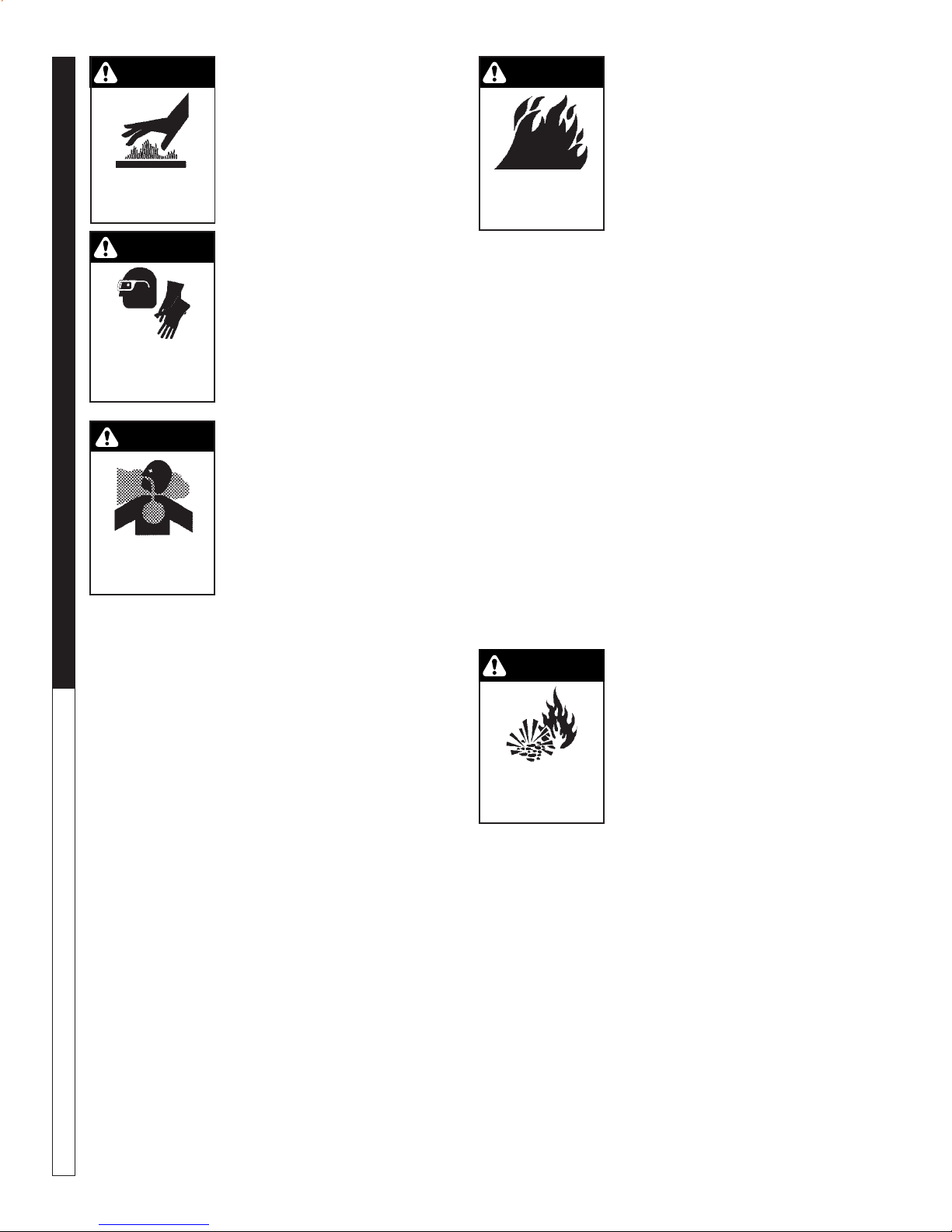
IMPORTANT SAFETY
INFORMATION
WARNING: When using this machine basic precautions should always be follo wed, including the f ollowing:
CAUTION
READ OPERATOR’S
MANUAL
THOROUGHLY
PRIOR TO USE.
2. All installations must comply with local codes. Contact your electrician, plumber, utility company or
the selling distributor for specific details.
CAUTION: To reduce the risk of
injury, read operating instructions carefully before using.
1. Read the owner's manual
thoroughly. Failure to follow
instructions could cause malfunction of the machine and
result in death, serious bodily
injury and/or proper ty damage.
97-610, 97-6152 • REV. 7/04
T o comply with the National Electrical code (NFPA
70) and provide additional protection from risk of
electric shock, this pressure washer is equipped
with a UL approved ground f ault circuit interrupter
(GFCI) power cord for machines rated 250V 30
amp or less, single phase.
3. Know how to stop the machine and bleed pressures quickly. Be thoroughly familiar with the controls.
4. Stay alert. Watch what you are doing.
WARNING: Flammable liquids
can create fumes which can ignite causing property damage
or severe injury .
5. Risk of explosion - Do not
spray flammable liquids or
RISK OF EXPLOSION:
DO NOT SPRAY
FLAMMABLE
LIQUIDS.
operate in an explosiv e location. Operate only where
open flame or torch is permitted.
WARNING: Keep water spray
away from electrical wiring or
fatal electric shock may result.
Read warning tag on electrical
cord.
6. To protect the operator from
KEEP WA TER SPRAY
AWAY FROM
ELECTRICAL WIRING.
electrical shock, the machine
must be electrically
grounded. It is the responsibility of the owner to connect
this machine to a UL grounded receptacle of proper
voltage and amperage ratings. Do not spray water on or near electrical components. Do not touch
machine with wet hands or while standing in water. Always disconnect power before servicing.
WARNING: Spray gun kicks back. Hold with both
hands.
7. Grip cleaning wand securely with both hands before starting the cleaner. Failure to do this could
result in injury from a whipping wand.
WARNING
W ARNING: Equipment can produce a high pressure stream of
fluid that can pierce skin and its
underlying tissues, leading to
serious injury and possible
amputation.
RISK OF INJECTION
OR SEVERE INJURY
TO PERSONS. KEEP
CLEAR OF NOZZLE.
8. High pressure developed by
these machines can cause
personal injury or equipment
damage. Use caution when operating. Do not direct discharge stream at anyone or at any part of
the body , or se v ere injury or death will result. This
machine is to be used only by qualified operators.
PRESSURE WASHER
OPERATOR’S MANUAL
5
WARNING
CAUTION: Hot discharge fluid.
Do not touch or direct discharge stream at persons.
9. Never make adjustments on
machine while in operation.
EXTREMEL Y HOT :
USE CAUTION WHEN
OPENING LID.
WARNING
PRESSURE W ASHER
WARNING: High pressure can
cause paint chips or other particles to become airborne and
fly at high speeds.
EYEWEAR AND
CLOTHING MUST
OPERATOR’S MANUAL
PROTECTIVE
BE WORN.
WARNING
10. Eye safety devices and foot
protection must be worn
when using this equipment.
WARNING: Risk of asphyxiation. Use this product only in a
well ventilated area.
11. When the machine is working, do not cover or place in
a closed space where venti-
RISK OF
ASPHYXIATION.
USE ONLY IN A WELL
VENTILA TED AREA.
lation is insufficient.
12. Machines with spray guns
should not be operated with
the trigger in the off position
for extensive periods of time as this may cause
damage to the pump.
13. Protect from freezing.
14. Be certain all quick coupler fittings are secured
before using pressure washer.
15. Do not allow acids, caustic, or abrasive fluids to
pass through the pump.
16. Inlet w ater m ust be cold and clean fresh w ater.
17. To reduce the risk of injury, close supervision is
necessary when a machine is used near children.
Do not allow children to operate the pressure
washer. This machine must be attended during
operation.
18. The best insurance against an accident is precaution and knowledge of the machine.
19. Do not operate this product when fatigued or under the influence of alcohol or drugs. K eep operating area clear of all persons.
20. Do not replace LP tank while machine is running.
Serious injury could result.
WARNING
WARNING: Use only vapor pr opane fuel.
21. This equipment is designed
to run on vapor fuel. Do not
use liquid fuel. Ha ve a qualified serviceman install and
RISK OF FIRE.
DO NOT USE WITH
FLAMMABLE LIQUIDS.
service your equipment.
22. Never expose a spark or
flame where unburned gas
may be present.
23. Never attempt to light pilot unless pilot manual
valve has been shut off f or 5 min utes.
24. A conv ersion kit, as supplied by the manuf acturer,
shall be used to convert natural gas to propane.
25. L.P. gases are hea vier than air and will spill out on
the floor. Therefore always provide adequate space
and ventilation around these machines. Install
machine 18" above the floor .
26. Manufacturer will not be liable for any changes
made to our standard machines, or any components not purchased from the manufacturer .
27. Do not overreach or stand on unstable suppor t.
Keep good footing and balance at all times .
28. Follow maintenance instructions specified in the
manual.
29. When making repairs disconnect from electrical
source and shut off gas valve.
30. Turn burner off, open spray gun and cool to 100°
F before turning machine off.
WARNING
31. Extinguish any open flame
and test all joints with a soap
solution. If odor persists , call
your gas supplier immediately.
32. Not suitable for connection
RISK OF EXPLOSION:
IF GAS SMELL
PRESENT TURN
OFF SUPPLY
to Type B gas vent if the stack
temperature exceeds 243° C
(470° F).
33. A draft div erter shall be installed if this machine is
going to be permanently installed and vented to
the outside of the building.
6
97-610, 97-6152 • REV. 7/04
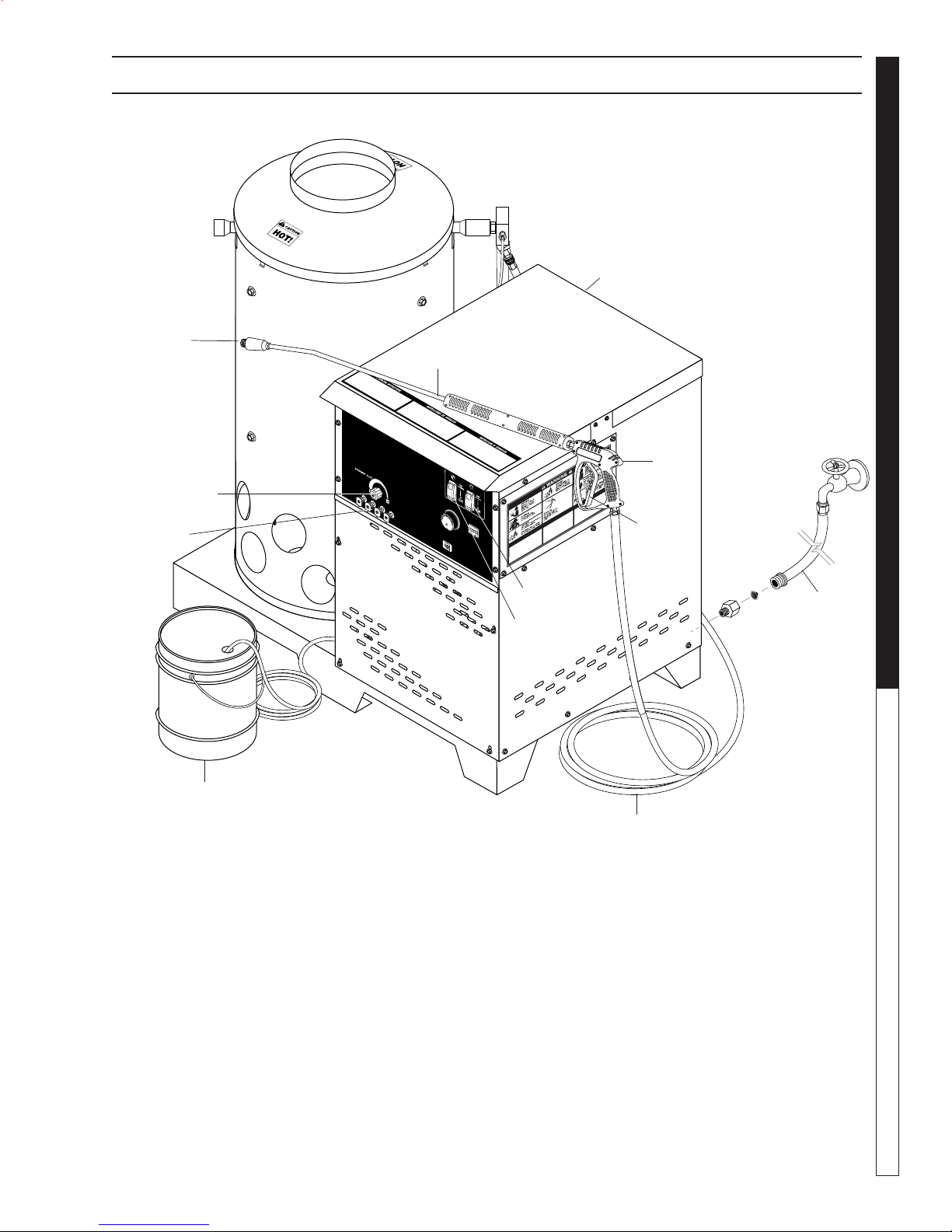
COMPONENT IDENTIFICATION
Main Gas
Supply Inlet
1/2 psig
PRESSURE WASHER
Wand Quick
Coupler
Detergent
Valve
Pressure
Nozzle
Spray
Wand
Burner
Switch
Pump
Switch
OPERATOR’S MANUAL
Spray
Gun
Trigger
Water Supply
Hose
(not included)
Detergent Bucket
(optional)
Pump — Dev elops high pressure.
Pump/Burner Switch— Controls operation on ma-
chine.
Spray Gun — Controls the application of water and
detergent onto cleaning surface with trigger device. Includes safety latch.
Detergent V alve — Allows you to siphon and mix detergents.
Wand — Must be connected to the spra y gun.
High Pressure
Hose
High Pressure Hose — Connect one end to water
pump discharge nipple and the other end to spray gun.
Wand Quick Coupler — Pulling the br ass collar back
allows the insertion of pressure nozzle.
Note: If trigger on spray gun is released for more
than 2 minutes, water will leak from valve. Warm
water will discharge from pump protector onto
floor. This system prevents internal pump damage.
7
97-610, 97-6152 • REV. 7/04
PRESSURE W ASHER
OPERATOR’S MANUAL
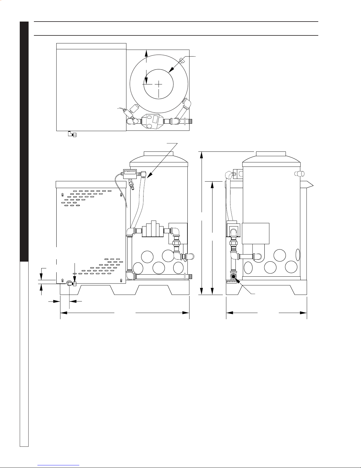
INSTALLATION
9.57" I.D.
11-3/4"
High Pressure Out
Fresh Water
In 1.0" GHF
1-1/4"
3.0"
44-1/4"
49-0"
38-3/8"
Gas In
1-1/2" NPT-M
27-1/2"
8
97-610, 97-6152 • REV. 7/04
INSTALLATION
PRESSURE WASHER
INSTALLATION
Place machine in a convenient location providing ample
support, drainage and room for maintenance (see page
6).
Location:
The location should protect the machine from damaging
environmental conditions, such as wind, rain and freezing.
1. The machine should be run on a level surface
where it is not readily influenced by outside sources
such as strong winds, freezing temperatures, rain,
etc. The machine should be located considering
accessibility for the replacing of components and
the refilling of detergents, adjustments and maintenance. Normal precautions should be taken by
the operator of the machine to prevent excess
moisture from reaching the power unit or electrical controls.
2. It is recommended that a partition be made between the wash area and the machine to prev ent
direct spray from the spray gun from coming in
contact with the machine. Excess moisture reaching the power unit or electrical controls will reduce
the machine’s lif e and may cause electrical shorts.
3. During installation of the machine, beware of poorly
ventilated locations or areas where exhaust fans
may cause an insufficient supply of oxygen. Sufficient combustion can only be obtained when there
is a sufficient supply of oxygen available for the
amount of fuel being burned. If it is necessary to
install a machine in a poorly ventilated area, outside fresh air may hav e to be piped to the burner
and a fan installed to bring the air into the area.
4. Do not locate near any combustible material. K eep
all flammable material at least 20 feet awa y.
Allow enough space for servicing the machine.
Local code will require certain distances from floor
and walls. (Two feet away should be adequate).
WARNING: A void small areas or near exhaust fans.
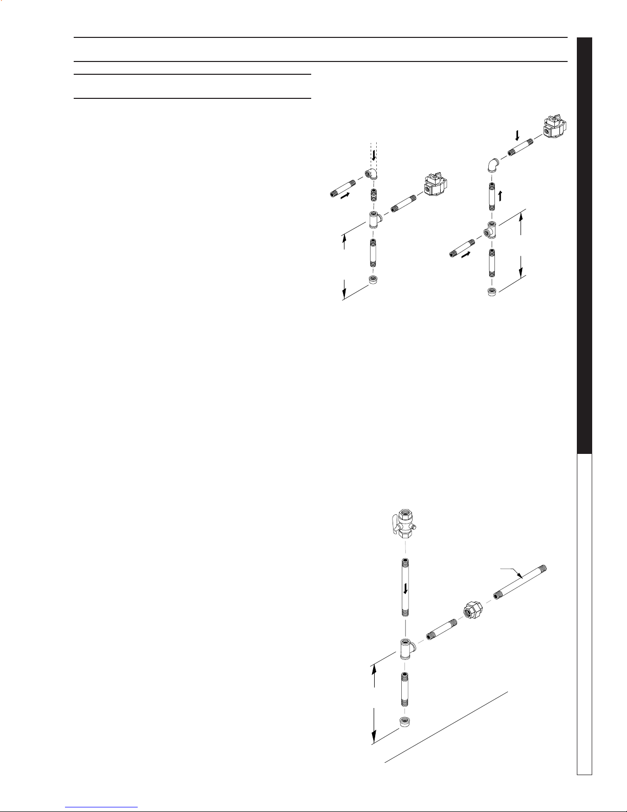
Gas Piping:
Figure 1: DRIP LEG
Drop
Gas
Valve
3"
(7.62 mm)
Minimum
Sediment trap (drip leg) must be
installed in the supply line.
Install a union in the gas line adjacent to and upstream
from the control manifold and downstream from the
manual main shut-off valve. A 1/8" NPT plugged tapping accessible for test gauge connection shall be installed immediately upstream of the gas supply connection for the purpose of determining the gas supply
pressure to the burner, and to pre vent damage to gas
valve.
If a manual gas shut off valve is not in the gas supply
line within six feet of the machine and in an accessible
location, one shall be installed.
Figure 2: UNION LOCATION
Manual
Shut-Off Valve
1/8" NPT Plugged
Pressure Gauge
Flow
Port Location
1/4" Test Port
(6" - 14 W.C.
or 1/2" PSIG)
Gas
Valve
3" (7.62 mm)
Minimum
To
Gas Valve
OPERATOR’S MANUAL
Gas Codes:
Confer with local gas company and with proper municipal officials regarding any specific code or regulations governing the installation. The installation must
conform to local codes.
Electrical:
The machine, when installed, must be electrically
grounded in accordance to local codes. Check for
proper power supply using a volt meter; chec k the serial plate for the correct requirements.
3" (7.62 mm)
Minimum
97-610, 97-6152 • REV. 7/04
Tee
Union
Control Manifold
Pipe
Cap
Floor Level
9

INSTALLATION
The following pipe and stack sizes are just recommendations. Always consult a local plumber and venting
contractor for local codes and regulations during installation.
The following tables are maximum capacity of final
stage pipe in thousands of Btu/hr of commercial propane
From first stage regulator (at tank) to second stage
PRESSURE W ASHER
regulator
The chart below is based on incoming gas pressure of
10 PSI and a pressure drop of 1 PSI. Numbers are for
straight schedule 40 pipe; fittings further reduce capacity.
ENAPORP
eziSepiPnorI
OPERATOR’S MANUAL
epiPfohtgneL
).tf(
0193332896
0259229974
0334814583
0477518923
"2/1"4/3
From second stage regulator to machine.
The following chart is based on incoming gas pressure
of 11 w.c.i. and a pressure drop of .5 w.c.i. Numbers
are for straight schedule 40 pipe; fittings further reduce
capacity.
ENAPORP
fohtgneL
).tf(epip
011928066411
02002814887
03161633236
04731782145
05221552084
06011132534
07201212004
0849891273
0978581943
00148571033
"2/1"4/3"1
eziSepiPnorI
0589313292
0676219462
0756117342
0848017622
0971017212
0011699002
0512773161
0020661831
0525854221
0030359011
0538840201
004454949
054624098
005204148
The chart below is based on gas pressure in the range
0-.5 PSI, specific gravity of .6, and pressure loss of
.5 w.c.i. Numbers are f or straight schedule 40 pipe; fittings further reduce capacity.
SAGLARUTAN
fohtgneL
).tf(epiP
01063086004100120593
0205256405906410572
0300257307708110022
040710230660990091
051515820850090861
068310620350180251
075210420940570041
088110220640960031
090115020340560221
0013015910040260511
05148061523005059
"4/3"1"4/1-1"2/1-1"2
eziSepiPnorI
10
00227531082034008
97-610, 97-6152 • REV. 7/04
INSTALLATION
PRESSURE WASHER
Venting:
This machine is used indoors which requires ventilation.
When venting the machine, if the machine is to be in
an enclosed area with a vent pipe, be sure it is the
same size as the stack on the machine. P oor dr aft will
cause the machine to soot and not operate efficiently .
When placing the machine for installation, position the
vent pipe to be as straight as possible and to protrude
through the roof of the building at a proper location
and at sufficient height to eliminate down-draft. Venting of a gas fired machine shall be installed with a downdraft diverter located about 3 ft. abo ve machine.
Input - BTU Per Hour Draft Hood & Flue Pipe
Size
250,000 - 320,000 8 inch
320,000 - 410,000 9 inch
410,000 - 600,000 10 inch
600,000 - 750,000 12 inch
NOTE: If the vent pipe e xceeds 10 ft. in length, or contains more than two elbows, use next size larger pipe
and draft diverter or the burner will not ignite. No mo vable vent pipe damper should be used on any installation.
ceiling, each to be sized on the basis of one square
inch or more of free area for each 1,000 BTU input per
hour (see Figure 4).
When a room is of unusually tight construction and
has a ventilating fan, which may be used for exhausting air outdoors -or has a vented exhaust — it is recommended that combustion air be supplied to the enclosed room through intakes extending to the outside
of the building and terminating in down-turned fittings.
These should be suitably arranged to prev ent obstruction from snow or rain, and include a protecting screen
not smaller than 1/4 inch mesh.
Figure 4
Ventilating Air Opening.
1 square inch for each
1000 BTU per hour input.
OPERATOR’S MANUAL
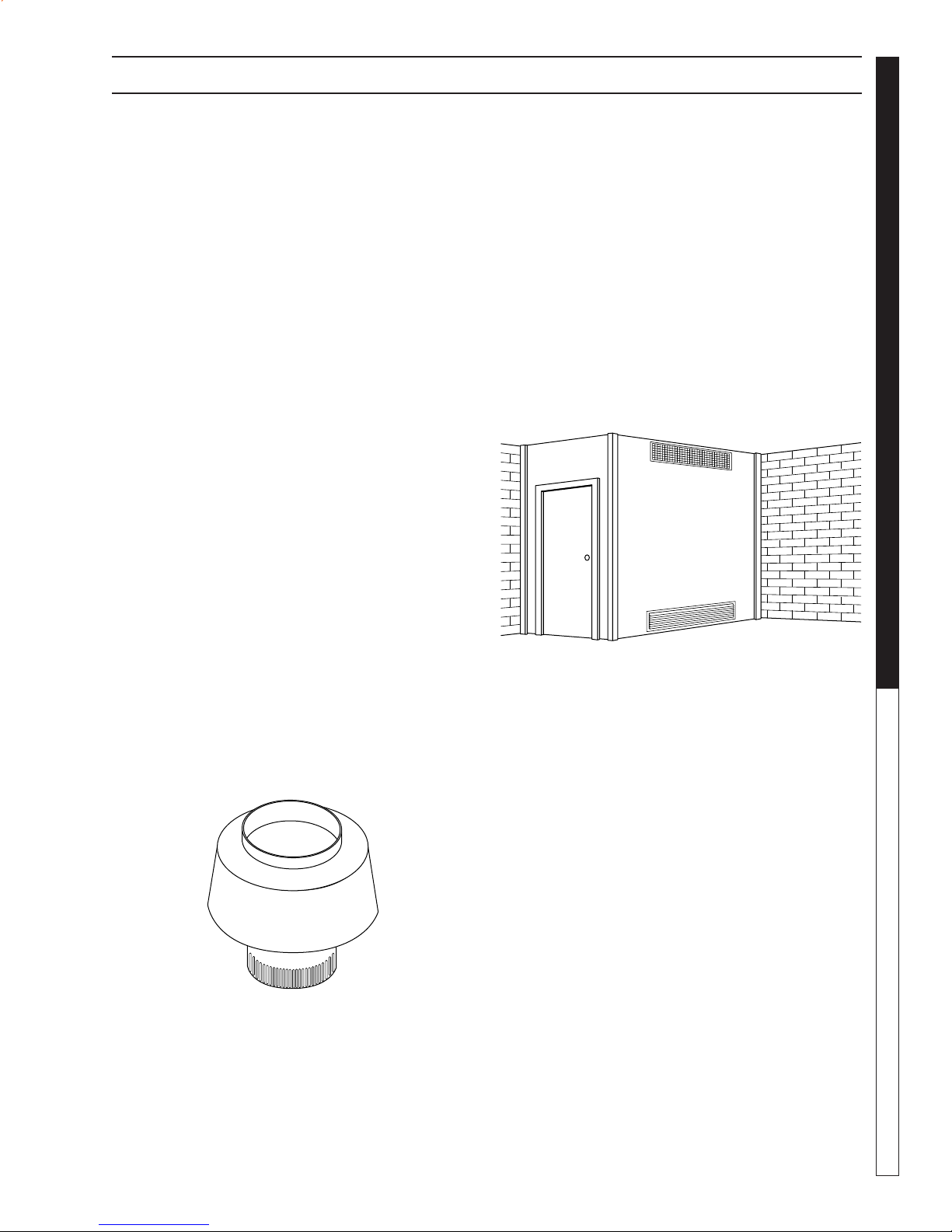
Draft Diverter:
Install the draft diverter above the heating coil. The
diverter enhances the draft through the burner by severing the chimney effect created in sections of vent
pipe positioned below . It also helps prevent freezing of
the coil due to wind chill factors.
Figure 3
Optional
When in a tightly closed room without ventilation openings to the outdoors or other rooms, provisions shall
be made for supplying air for comb ustion through special openings, one near the floor and the other near the
Illustration showing air openings necessary
to supply air for combustion when installed
in an enclosed room.
Water Source:
The water source for the machine should be supplied
by a 5/8" I.D . garden hose with a city water pressure of
not less than 30 PSI. If the w ater supply is inadequate,
or if the garden hose is kinked, the machine will run
very rough and the burner will not fire.
Water Connection:
Connect the high pressure hose by pulling the coupler
collar back and then inserting it onto the discharge
nipple. Secure it b y pushing the collar f orward.
Attach the wand into the spray gun using teflon tape
on the pipe threads to avoid leaks .
Inspection and Testing Gas Piping:
The building structure should not be weakened by installing the gas piping. The piping should not be supported by other piping, but should be firmly supported
with gas hooks, straps, bands or hangers. Butt or lap
welded pipe should not be run through or in an air duct
or clothes chute.
11
97-610, 97-6152 • REV. 7/04

INSTALLATION
Before turning gas under pressure into piping, all openings from which gas can escape should be closed. Immediately after turning on gas, the system should be
checked for leaks. This can be done by watching the
1/2 cubic foot test dial for 5 minutes f or any mov ement
or by soaping each pipe connection and watching for
bubbles. If a leak is found, make the necessary repairs
and repeat the above test.
PRESSURE W ASHER
Defective pipes or fittings should be replaced and not
repaired. Never use a flame or fire in any form to locate gas leaks — use a soap solution.
After the piping and meter have been checked completely , purge the system of air. DO NOT b leed the air
inside an enclosed room.
During pressure testing of the system at test pressures
in excess of 1/2 PSIG, the appliance and its individual
shut-off valve must be disconnected from the gas supply piping system or damage to the gas valve will oc-
OPERATOR’S MANUAL
cur.
GNINRAW
.efilfossolroyrujni
YTEFASRUOYROF
.ecnailppaynathgilotyrttonoD•
.gnidliubruoyni
.snoitcurtsnis'reilppussagehtwolloF.enohp
.noisolpxero
.retawrednu
12
Gas Pressure:
The ideal incoming gas pressure is 11 water column
inches or w.c.i. (min. 6 wc”, max. 14 wc” or 1/2 PSIG).
The correct operating manifold pressure f or natural gas
is 3.5 wc” The operating manifold pressure f or propane
gas is 10 wc” By adjusting the gas valv e pressure regulator between 3 and 4 wc” a side range can be achie ved
for natural gas. Propane is 6-10 wc”.
If the desired input rating cannot be obtained within
the above manif old pressure adjusting range, then the
next size larger or smaller burner orifice should be
used.
CHECK LIST BEFORE
CAUTION! If “NO” is chec ked on any of the follo wing sixteen questions, do not operate this machine.
GNITHGILEROFEBDAERYTEFASRUOYROF
roerifa,yltcaxesnoitcurtsniesehtwolloftonoduoyfI
lanosrep,egamadytreporpgnisuac,tluseryamnoisolpxe
.dnahybdethgilebtsumhcihwtolipasahecnailppasihT.A
.yltcaxesnoitcurtsniesehtwollof,tolipehtgnithgilnehW
aeraecnailppaehtdnuorallallemsGNITHGILEROFEB.B
emosesuacebroolfehtottxenllemsoteruseB.sagrof
.roolfehtnoeltteslliwdnarianahtreivaehsisag
"SAGLLEMSUOYFIODOTTAHW"
enohpynaesutonod,hctiwslacirtceleynahcuottonoD•
s'robhgienamorfreilppussagruoyllacyletaidemmI•
.tnemtrapederifehtllac,reilppusruoyhcaertonnacuoyfI•
lortnocsagehtnrutronihsupotdnahruoyylnoesU.C
nrutronihsuptonlliwbonkehtfI.slootesureveN.bonk
ecivresdeifilauqallac;tiriaperotyrtt'nod,dnahyb
erifanitluseryamriaperdetpmettarodecroF.naicinhcet
rednuneebsahtrapynafiecnailppasihtesutonoD.D
otnaicinhcetecivresdeifilauqallacyletaidemmI.retaw
ehtfotrapynaecalperotdnaecnailppaehttcepsni
neebsahhcihwlortnocsagynadnametsyslortnoc
97-610, 97-6152 • REV. 7/04
?yarps
?skael
?sedoc
STARTING:
SEYON
naybdetcepsnineebylppussagsaH
?sedoclacolteemotrotcartnocdezirohtua
dnatfardnwodmorfdetcetorpenihcamsI
?dniwevissecxe
retawroerutsiommorfdedleihsenihcamsI
tiucricehteradnatcerrocegatlovehtsI
etauqedadrocylppusdnarekaerb
etalplairesdnasnoitacificepsotgnidrocca
?noitaton
?dednuorgyllacirtceleenihcamehtsI
?ylppusretawelpmaerehtsI
neebsesagrosdiuqilelbammalfllaevaH
?noitacolnoitallatsnimorfdevomer
UTBehtrofylppussagetauqedaerehtsI
?renrubehtfognitar
neewteberusserpylppussaggnimocnisI
?GISP2/1rosehcninmulocretaw41-6
neebrotalugersagreporpehtsaH
?emulovdnaerusserprofdellatsni
wollaotdetnevylreporpenihcamehtsI
?wolfriaetauqeda
,hguoneegralsknatenaporpehterA
gnizeerftneverpotgnitarotgnidrocca
?)ylnosenihcamenaporpropav(
sagrofdekcehcneebsenilsagevaH
lacolhtiwdekcehcneebsenilsagevaH
enihcamsihtgnisusrotarepollaevaH
daeryehtevah&ylreporpdetcurtsnineeb
?launameht
gnidroccadellatsnineebenihcamehtsaH
?snoitcurtsnilaunams'rotarepoot
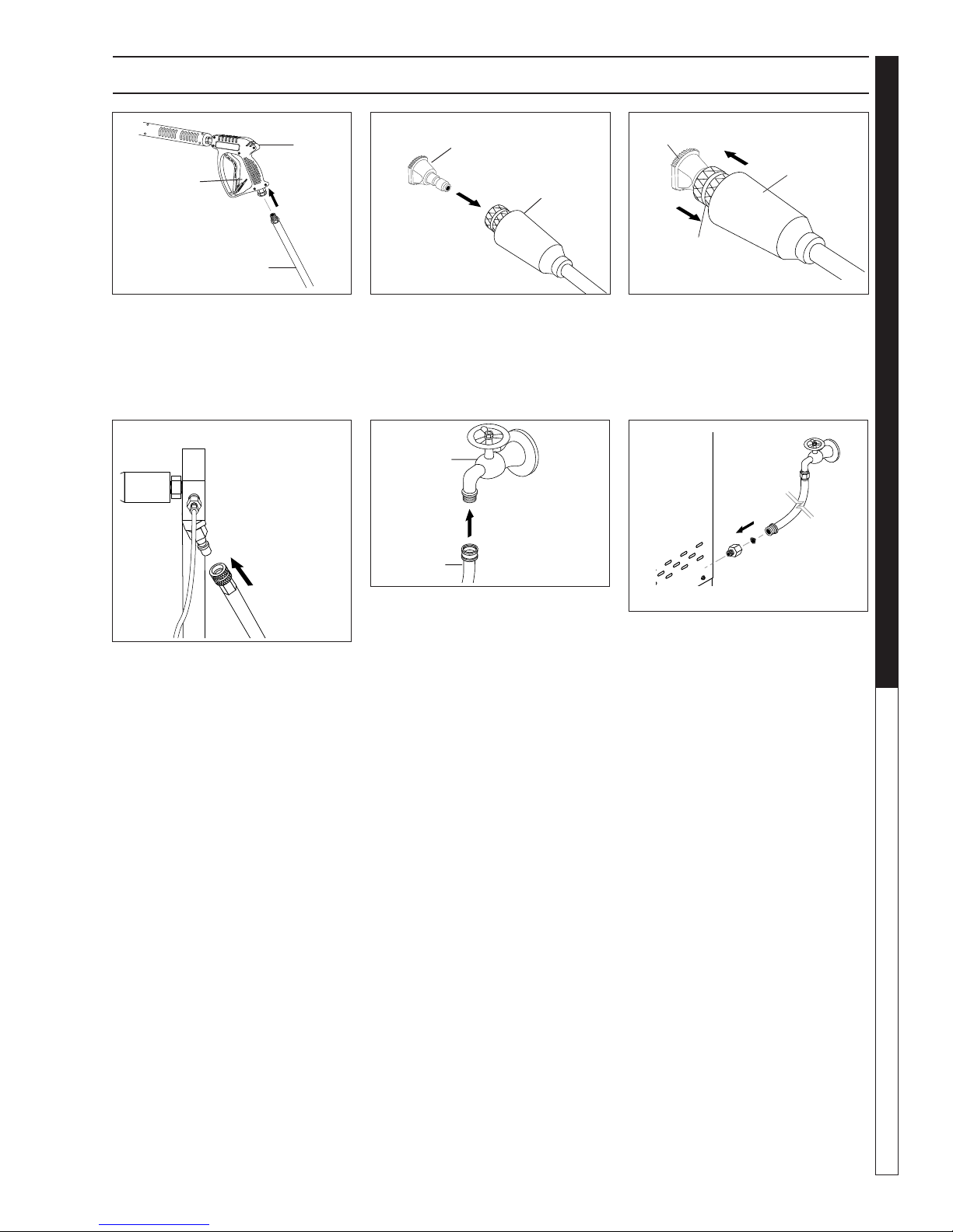
ASSEMBLY INSTRUCTIONS
PRESSURE WASHER
Spray
Gun
Safety
Latch
High Pressure
Hose
STEP 1: Attach the high pressure
hose to the spray gun using teflon
tape on hose threads.
Pressure
Nozzle
Wand
Coupler
STEP 2: Pull the spring-loaded col-
lar of the wand coupler back to insert your choice of pressure nozzle.
CAUTION: Never replace nozzles
without engaging the safety latch
on the spray gun trigger .
Cold
Water
Source
Garden
Hose
Pressure
Nozzle
Wand
Coupler
Wand
Collar
STEP 3: Release the coupler col-
lar and push the nozzle until the
collar clicks. Pull the nozzle to
make sure it is seated properly.
Garden
Hose
Water Inlet
OPERATOR’S MANUAL
STEP 4: Connect the high pressure
hose to the pump discharge fitting.
Push coupler collar forward until secure.
STEP 5: Connect garden hose to the
cold water source.
STEP 6: Check inlet filters, remove
debris, then connect the garden
hose to pump water inlet.
CAUTION: Do not run the pump
without water or pump damage
will result.
13
97-610, 97-6152 • REV. 7/04
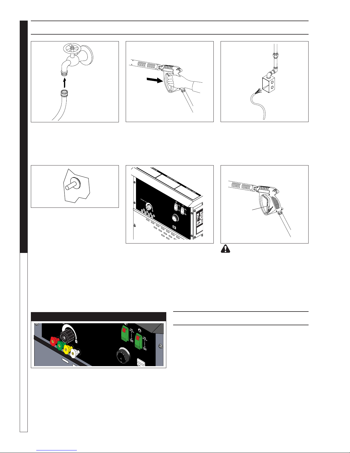
PRESSURE W ASHER
OPERATING INSTRUCTIONS
Cold
Water
Source
Garden
Hose
STEP 1: Review installation instruc-
tions prior to connecting garden
hose to the cold water source and
turn water on completely . Ne ver use
hot water .
OPERATOR’S MANUAL
STEP 4: Depress control knob and
hold it in. After 5 seconds, depress
the red ignitor until you hear a loud
click. Repeat 3 or 4 times if necessary until pilot is lit. If pilot does not
remain lit, repeat operation, allowing a longer period of time before
releasing the knob. After the pilot
lights, continue to hold the control
knob down for 1 minute. Note: Sufficient time must be allowed for a
proper size pilot flame to heat the
thermocouple and hold the safety
magnet in a locked-up position.
STEP 2: Trigger the spray gun to
eliminate trapped air then wait for a
steady flow of water to emerge from
the spray nozzle.
STEP 5: Turn gas cock dial to “PILOT” position.Release dial and turn
to full ON. Push pump s witch ON, or
turn to pump position and pull the
trigger on the spray gun allowing
cold water to flow . T o activ ate the gas
control valve f or hot water , push the
burner switch to the ON position and
pull the trigger on the spray gun.
STEP 3: Have an electrician connect
power supply into junction box according to information shown on the
serial plate before turning gas valve
dial to “pilot” position.
Safety
Latch
WARNING! Never replace
nozzles without engaging the
safety latch on the spray gun trigger.
NOZZLES
The five color-coded quick connect nozzles provide a
wide array of spra y widths from 0° to 45° and are easily
accessible when placed in the conv enient rubber nozzle
holder, which is provided on the front of the machine .
NOTE: For a more gentle rinse, select the white 40° or
green 25° nozzle. To scour the surface, select the yellow 15° or red 0° nozzle. To apply detergent select the
14
black nozzle.
AUTO IGNITION OPTION
If your machine has A uto Ignition option,
follow these steps.
1. Have electrician connect power supply into junction box according to information shown on serial
plate and open main gas supply.
2. Push pump switch to “ON” position, pull trigger on
spray gun.
3. After water and pressure is e xiting pressure nozzle
push burner switch “ON”.
be set at 200°.
4. The pilot will ignite first then you will notice a flash
of light indicating complete ignition.
should hear a clicking sound before the pilot
ignites.
97-610, 97-6152 • REV. 7/04
Note: thermostat should
Note: You
 Loading...