

Page 1

HNG
OPERATOR’S MANUAL
■ HNG-4020 ■ HNG-3530 ■ HNG-5030
L
D
I
S
E
®
T
For technical assistance or the SHARK dealer nearest you, call 1-800-771-1881
or visit our website at www.shark-pw .com
97-610
Page 2

Page 3

Introduction & Important Safety Information 5-6
Component Identification 7
Installation 8
Installation Guide 9-12
Check List Before Starting 12
Assembly Instructions 13
Operating Instructions 14
Detergents & General Cleaning Techniques 13-14
Shut-Down & Cleanup 15
Storage 15
Basic Facts 16
Troubleshooting 18-19
Maintenance & Service 20-23
CONTENTS
Heating Coils 20
Propane Gas 21
Burner Features 21-22
Burner T roubleshooting 22-23
Preventativ e Maintenance Schedule & Oil Change Record 24
Hose & Spray Gun Assembly 25
Exploded Vie w , Left Side 26
Exploded Vie w , Right Side 27
Exploded View , Parts List 28-30
TNG Float Tank Assembly 31
Burner Assembly , Exploded View 32
Burner Assembly, Exploded Vie w, Parts List 33
Control Panel 34
Control Panel, P arts List 35
Electrical Box, Standard 36
Electrical Box, Standard, Parts List 37
3
97-610, 97-6152 • REV. 4/04
Page 4

CONTENTS
Electrical Box, Time Dela y 38
Electrical Box, Time Dela y, Parts List 39
Electrical Box, Auto Start 40
Electrical Box, Auto Start, Parts List 41
Warranty
Model Number ______________________________
Serial Number ______________________________
Date of Purchase ____________________________
The model and serial numbers will be found on a decal attached to
the pressure washer. You should record both serial number and
date of purchase and keep in a safe place f or future reference.
4
97-610, 97-6152 • REV. 4/04
Page 5

INTRODUCTION
WARNING
WARNING
Thank you for purchasing our Pressure Washer.
This manual covers the operation and maintenance of
the 301001D , 301007D, 352001A, 352007A, 402001A,
402007A, 402001B, 402007B, 402001C, 402007C,
502001A, 502007A, 502001B, 502007B, 502001C,
502007C, 353001A, 353007A, 353001B, 353007B,
353001C, 353007C, 503001B , 503007B, 503001C and
503007C model washers. All information in this manual
is based on the latest product information available at
the time of printing.
We reserve the right to make changes at any time without incurring any obligation.
This machine was designed for
maximum use of 4 hours per day,
5 days per week.
Owner/User Responsibility:
The owner and/or user must have an understanding
of the manufacturer’ s operating instructions and warnings before using this pressure washer . W arning information should be emphasized and understood. If the
operator is not fluent in English, the manufacturer’s
instructions and warnings shall be read to and discussed with the operator in the operator’s native language by the purchaser/owner, making sure that the
operator comprehends its contents.
Owner and/or user must study and maintain for future
reference the manufacturers’ instructions
This manual should be considered a permanent
part of the machine and should remain with it if
machine is resold.
When ordering parts, please specify model and
serial number .
IMPORTANT SAFETY
INFORMATION
WARNING: When using this machine basic precautions should always be follo wed, including the f ollowing:
CAUTION
READ OPERATOR’S
MANUAL
THOROUGHLY
PRIOR TO USE.
2. All installations must comply with local codes. Contact your electrician, plumber, utility company or
the selling distributor for specific details.
CAUTION: To reduce the risk of
injury, read operating instructions carefully before using.
1. Read the owner's manual
thoroughly. Failure to follow
instructions could cause malfunction of the machine and
result in death, serious bodily
injury and/or proper ty damage.
97-610, 97-6152 • REV. 4/04
T o comply with the National Electrical code (NFPA
70) and provide additional protection from risk of
electric shock, this pressure washer is equipped
with a UL approved ground f ault circuit interrupter
(GFCI) power cord for machines rated 250V 30
amp or less, single phase.
3. Know how to stop the machine and bleed pressures quickly. Be thoroughly familiar with the controls.
4. Stay alert. Watch what you are doing.
WARNING: Flammable liquids
can create fumes which can ignite causing property damage
or severe injury .
5. Risk of explosion - Do not
spray flammable liquids or
RISK OF EXPLOSION:
DO NOT SPRAY
FLAMMABLE
LIQUIDS.
operate in an explosiv e location. Operate only where
open flame or torch is permitted.
WARNING: Keep water spray
away from electrical wiring or
fatal electric shock may result.
Read warning tag on electrical
cord.
6. To protect the operator from
KEEP WA TER SPRAY
AWAY FROM
ELECTRICAL WIRING.
electrical shock, the machine
must be electrically
grounded. It is the responsibility of the owner to connect
this machine to a UL grounded receptacle of proper
voltage and amperage ratings. Do not spray water on or near electrical components. Do not touch
machine with wet hands or while standing in water. Alwa ys disconnect pow er before servicing.
WARNING: Spray gun kicks back. Hold with both
hands.
7. Grip cleaning wand securely with both hands before starting the cleaner. Failure to do this could
result in injury from a whipping wand.
WARNING
W ARNING: Equipment can produce a high pressure stream of
fluid that can pierce skin and its
underlying tissues, leading to
serious injury and possible
amputation.
RISK OF INJECTION
OR SEVERE INJURY
TO PERSONS. KEEP
CLEAR OF NOZZLE.
8. High pressure developed by
these machines can cause
personal injury or equipment
damage. Use caution when operating. Do not direct discharge stream at anyone or at any part of
the body , or se v ere injury or death will result. This
machine is to be used only by qualified operators.
PRESSURE WASHER
OPERATOR’S MANUAL
5
Page 6

WARNING
CAUTION: Hot discharge fluid.
Do not touch or direct discharge stream at persons.
9. Never make adjustments on
machine while in operation.
EXTREMEL Y HOT :
USE CAUTION WHEN
OPENING LID.
WARNING
PRESSURE W ASHER
WARNING: High pressure can
cause paint chips or other particles to become airborne and
fly at high speeds.
EYEWEAR AND
CLOTHING MUST
OPERATOR’S MANUAL
PROTECTIVE
BE WORN.
WARNING
10. Eye safety devices and foot
protection must be worn
when using this equipment.
WARNING: Risk of asphyxiation. Use this product only in a
well ventilated area.
11. When the machine is working, do not cover or place in
a closed space where venti-
RISK OF
ASPHYXIATION.
USE ONLY IN A WELL
VENTILA TED AREA.
lation is insufficient.
12. Machines with spray guns
should not be operated with
the trigger in the off position
for extensive periods of time as this may cause
damage to the pump.
13. Protect from freezing.
14. Be certain all quick coupler fittings are secured
before using pressure washer.
15. Do not allow acids, caustic, or abrasive fluids to
pass through the pump.
16. Inlet w ater m ust be cold and clean fresh w ater.
17. To reduce the risk of injury, close supervision is
necessary when a machine is used near children.
Do not allow children to operate the pressure
washer. This machine must be attended during
operation.
18. The best insurance against an accident is precaution and knowledge of the machine.
19. Do not operate this product when fatigued or under the influence of alcohol or drugs. K eep operating area clear of all persons.
20. Do not replace LP tank while machine is running.
Serious injury could result.
WARNING
WARNING: Use only vapor pr opane fuel.
21. This equipment is designed
to run on vapor fuel. Do not
use liquid fuel. Ha ve a qualified serviceman install and
RISK OF FIRE.
DO NOT USE WITH
FLAMMABLE LIQUIDS.
service your equipment.
22. Never expose a spark or
flame where unburned gas
may be present.
23. Never attempt to light pilot unless pilot manual
valve has been shut off f or 5 min utes.
24. A conv ersion kit, as supplied by the manuf acturer,
shall be used to convert natural gas to propane.
25. L.P. gases are heavier than air and will spill out on
the floor. Therefore always provide adequate space
and ventilation around these machines. Install
machine 18" above the floor .
26. Manufacturer will not be liable for any changes
made to our standard machines, or any components not purchased from the manufacturer .
27. Do not overreach or stand on unstable support.
Keep good footing and balance at all times .
28. Follow maintenance instructions specified in the
manual.
29. When making repairs disconnect from electrical
source and shut off gas valve.
30. Turn burner off, open spray gun and cool to 100°
F before turning machine off.
WARNING
31. Extinguish any open flame
and test all joints with a soap
solution. If odor persists , call
your gas supplier immediately.
32. Not suitable for connection
RISK OF EXPLOSION:
IF GAS SMELL
PRESENT TURN
OFF SUPPLY
to Type B gas vent if the stack
temperature exceeds 243° C
(470° F).
33. A draft div erter shall be installed if this machine is
going to be permanently installed and vented to
the outside of the building.
6
97-610, 97-6152 • REV. 4/04
Page 7

COMPONENT IDENTIFICATION
Main Gas
Supply Inlet
1/2 psig
PRESSURE WASHER
Wand Quick
Coupler
Detergent
Valve
Pressure
Nozzle
Spray
Wand
Burner
Switch
Pump
Switch
OPERATOR’S MANUAL
Spray
Gun
Trigger
Water Supply
Hose
(not included)
Detergent Bucket
(optional)
Pump — Dev elops high pressure.
Pump/Burner Switch— Controls operation on ma-
chine.
Spray Gun — Controls the application of water and
detergent onto cleaning surface with trigger device. Includes safety latch.
Detergent V alve — Allows you to siphon and mix detergents.
Wand — Must be connected to the spra y gun.
High Pressure
Hose
High Pressure Hose — Connect one end to water
pump discharge nipple and the other end to spray gun.
Wand Quick Coupler — Pulling the br ass collar back
allows the insertion of pressure nozzle.
Note: If trigger on spray gun is released for more
than 2 minutes, water will leak from valve. Warm
water will discharge from pump protector onto
floor. This system prevents internal pump damage.
7
97-610, 97-6152 • REV. 4/04
Page 8

PRESSURE W ASHER
OPERATOR’S MANUAL
INSTALLATION
9.57" I.D.
11-3/4"
High Pressure Out
Fresh Water
In 1.0" GHF
1-1/4"
3.0"
44-1/4"
49-0"
38-3/8"
Gas In
1-1/2" NPT-M
27-1/2"
8
97-610, 97-6152 • REV. 4/04
Page 9

INSTALLATION
PRESSURE WASHER
INSTALLATION
Place machine in a convenient location providing ample
support, drainage and room for maintenance (see page
6).
Location:
The location should protect the machine from damaging
environmental conditions, such as wind, rain and freezing.
1. The machine should be run on a level surface
where it is not readily influenced by outside sources
such as strong winds, freezing temperatures, rain,
etc. The machine should be located consider ing
accessibility for the replacing of components and
the refilling of detergents, adjustments and maintenance. Normal precautions should be taken by
the operator of the machine to prevent excess
moisture from reaching the power unit or electrical controls.
2. It is recommended that a partition be made between the wash area and the machine to prev ent
direct spray from the spray gun from coming in
contact with the machine. Excess moisture reaching the power unit or electrical controls will reduce
the machine’s lif e and may cause electrical shorts.
3. During installation of the machine, beware of poorly
ventilated locations or areas where exhaust fans
may cause an insufficient supply of oxygen. Sufficient combustion can only be obtained when there
is a sufficient supply of oxygen available for the
amount of fuel being burned. If it is necessary to
install a machine in a poorly ventilated area, outside fresh air may hav e to be piped to the burner
and a fan installed to bring the air into the area.
4. Do not locate near any combustible material. K eep
all flammable material at least 20 feet awa y.
Allow enough space for servicing the machine.
Local code will require certain distances from floor
and walls. (Two feet awa y should be adequate).
WARNING: A void small areas or near exhaust fans.
Gas Piping:
Figure 1: DRIP LEG
Drop
Gas
Valve
3"
(7.62 mm)
Minimum
Sediment trap (drip leg) must be
installed in the supply line.
Install a union in the gas line adjacent to and upstream
from the control manifold and downstream from the
manual main shut-off valve. A 1/8" NPT plugged tapping accessible for test gauge connection shall be installed immediately upstream of the gas supply connection for the purpose of determining the gas supply
pressure to the burner, and to pre vent damage to gas
valve.
If a manual gas shut off valve is not in the gas supply
line within six feet of the machine and in an accessible
location, one shall be installed.
Figure 2: UNION LOCATION
Manual
Shut-Off Valve
1/8" NPT Plugged
Pressure Gauge
Flow
Port Location
1/4" Test Port
(6" - 14 W.C.
or 1/2" PSIG)
Gas
Valve
3" (7.62 mm)
Minimum
To
Gas Valve
OPERATOR’S MANUAL
Gas Codes:
Confer with local gas company and with proper municipal officials regarding any specific code or regulations governing the installation. The installation must
conform to local codes.
Electrical:
The machine, when installed, must be electrically
grounded in accordance to local codes. Check for
proper power supply using a volt meter; chec k the serial plate for the correct requirements.
3" (7.62 mm)
Minimum
97-610, 97-6152 • REV. 4/04
Tee
Union
Control Manifold
Pipe
Cap
Floor Level
9
Page 10

INSTALLATION
The following pipe and stac k sizes are just recommendations. Always consult a local plumber and venting
contractor for local codes and regulations during installation.
The following tables are maximum capacity of final
stage pipe in thousands of Btu/hr of commercial propane
From first stage regulator (at tank) to second stage
PRESSURE W ASHER
regulator
The chart below is based on incoming gas pressure of
10 PSI and a pressure drop of 1 PSI. Numbers are f or
straight schedule 40 pipe; fittings further reduce capacity.
ENAPORP
eziSepiPnorI
OPERATOR’S MANUAL
epiPfohtgneL
).tf(
0193332896
0259229974
0334814583
0477518923
0589313292
0676219462
0756117342
0848017622
0971017212
0011699002
0512773161
0020661831
0525854221
0030359011
0538840201
004454949
054624098
005204148
"2/1"4/3
From second stage regulator to machine.
The following chart is based on incoming gas pressure of 11 w.c.i. and a pressure drop of .5 w.c.i. Numbers are for straight schedule 40 pipe; fittings further
reduce capacity .
ENAPORP
fohtgneL
).tf(epip
011928066411
02002814887
03161633236
04731782145
05221552084
06011132534
07201212004
0849891273
0978581943
00148571033
The chart below is based on gas pressure in the range
0-.5 PSI, specific gravity of .6, and pressure loss of
.5 w.c.i. Numbers are for straight schedule 40 pipe;
fittings further reduce capacity.
"2/1"4/3"1
eziSepiPnorI
SAGLARUTAN
fohtgneL
).tf(epiP
01063086004100120593
0205256405906410572
0300257307708110022
040710230660990091
051515820850090861
068310620350180251
075210420940570041
"4/3"1"4/1-1"2/1-1"2
eziSepiPnorI
10
088110220640960031
090115020340560221
0013015910040260511
05148061523005059
00227531082034008
97-610, 97-6152 • REV. 4/04
Page 11

INSTALLATION
PRESSURE WASHER
Venting:
This machine is used indoors which requires ventilation.
When venting the machine, if the machine is to be in
an enclosed area with a vent pipe, be sure it is the
same size as the stack on the machine. P oor dr aft will
cause the machine to soot and not operate efficiently .
When placing the machine for installation, position the
vent pipe to be as straight as possible and to protrude
through the roof of the building at a proper location
and at sufficient height to eliminate down-draft. Venting of a gas fired machine shall be installed with a downdraft diverter located about 3 ft. abo ve machine.
Input - BTU Per Hour Draft Hood & Flue Pipe
Size
250,000 - 320,000 8 inch
320,000 - 410,000 9 inch
410,000 - 600,000 10 inch
600,000 - 750,000 12 inch
NOTE: If the vent pipe e xceeds 10 ft. in length, or contains more than two elbows, use ne xt size larger pipe
and draft diverter or the burner will not ignite. No mo vable vent pipe damper should be used on any installation.
the ceiling, each to be sized on the basis of one square
inch or more of free area for each 1,000 BTU input per
hour (see Figure 4).
When a room is of unusually tight construction and
has a ventilating fan, which ma y be used f or e xhausting air outdoors -or has a vented exhaust — it is recommended that combustion air be supplied to the enclosed room through intakes extending to the outside
of the building and terminating in down-turned fittings.
These should be suitably arranged to prev ent obstruction from snow or rain, and include a protecting screen
not smaller than 1/4 inch mesh.
Figure 4
Ventilating Air Opening.
1 square inch for each
1000 BTU per hour input.
OPERATOR’S MANUAL
Draft Diverter:
Install the draft diverter above the heating coil. The
diverter enhances the draft through the burner by severing the chimney effect created in sections of vent
pipe positioned below . It also helps prevent freezing of
the coil due to wind chill factors.
Figure 3
Optional
When in a tightly closed room without ventilation openings to the outdoors or other rooms, provisions shall
be made for supplying air for comb ustion through special openings, one near the floor and the other near
Illustration showing air openings necessary
to supply air for combustion when installed
in an enclosed room.
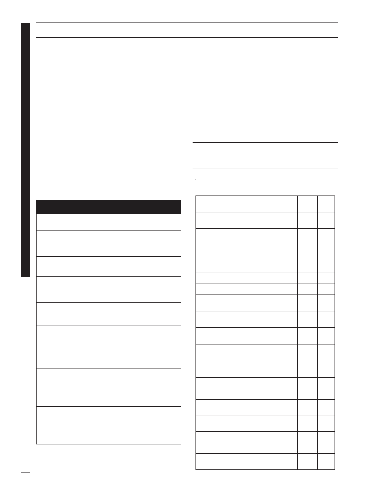
Water Source:
The water source for the machine should be supplied
by a 5/8" I.D . garden hose with a city water pressure of
not less than 30 PSI. If the w ater supply is inadequate,
or if the garden hose is kinked, the machine will run
very rough and the burner will not fire.
Water Connection:
Connect the high pressure hose by pulling the coupler
collar back and then inserting it onto the discharge
nipple. Secure it b y pushing the collar f orward.
Attach the wand into the spray gun using teflon tape
on the pipe threads to avoid leaks .
Inspection and Testing Gas Piping:
The building structure should not be weakened by installing the gas piping. The piping should not be supported by other piping, but should be firmly supported
with gas hooks, straps, bands or hangers. Butt or lap
welded pipe should not be run through or in an air duct
or clothes chute.
11
97-610, 97-6152 • REV. 4/04
Page 12
INSTALLATION
Before turning gas under pressure into piping, all openings from which gas can escape should be closed. Immediately after turning on gas, the system should be
checked for leaks. This can be done by watching the
1/2 cubic foot test dial for 5 minutes f or any mov ement
or by soaping each pipe connection and watching for
bubbles. If a leak is found, make the necessary repairs and repeat the above test.
PRESSURE W ASHER
Defective pipes or fittings should be replaced and not
repaired. Never use a flame or fire in any form to locate gas leaks — use a soap solution.
After the piping and meter have been checked completely , purge the system of air. DO NOT bleed the air
inside an enclosed room.
During pressure testing of the system at test pressures
in excess of 1/2 PSIG, the appliance and its individual
shut-off valve must be disconnected from the gas supply piping system or damage to the gas valve will oc-
OPERATOR’S MANUAL
cur.
GNINRAW
.efilfossolroyrujni
YTEFASRUOYROF
.ecnailppaynathgilotyrttonoD•
.gnidliubruoyni
.snoitcurtsnis'reilppussagehtwolloF.enohp
.noisolpxero
.retawrednu
12
Gas Pressure:
The ideal incoming gas pressure is 11 water column
inches or w.c.i. (min. 6 wc”, max. 14 wc” or 1/2 PSIG).
The correct operating manifold pressure f or natural gas
is 3.5 wc” The operating manifold pressure f or propane
gas is 10 wc” By adjusting the gas valv e pressure regulator between 3 and 4 wc” a side range can be achie ved
for natural gas. Propane is 6-10 wc”.
If the desired input rating cannot be obtained within
the above manif old pressure adjusting range, then the
next size larger or smaller burner orifice should be
used.
CHECK LIST BEFORE
CAUTION! If “NO” is checked on an y of the following sixteen questions, do not operate this machine.
GNITHGILEROFEBDAERYTEFASRUOYROF
roerifa,yltcaxesnoitcurtsniesehtwolloftonoduoyfI
lanosrep,egamadytreporpgnisuac,tluseryamnoisolpxe
.dnahybdethgilebtsumhcihwtolipasahecnailppasihT.A
.yltcaxesnoitcurtsniesehtwollof,tolipehtgnithgilnehW
aeraecnailppaehtdnuorallallemsGNITHGILEROFEB.B
emosesuacebroolfehtottxenllemsoteruseB.sagrof
.roolfehtnoeltteslliwdnarianahtreivaehsisag
"SAGLLEMSUOYFIODOTTAHW"
enohpynaesutonod,hctiwslacirtceleynahcuottonoD•
s'robhgienamorfreilppussagruoyllacyletaidemmI•
.tnemtrapederifehtllac,reilppusruoyhcaertonnacuoyfI•
lortnocsagehtnrutronihsupotdnahruoyylnoesU.C
nrutronihsuptonlliwbonkehtfI.slootesureveN.bonk
ecivresdeifilauqallac;tiriaperotyrtt'nod,dnahyb
erifanitluseryamriaperdetpmettarodecroF.naicinhcet
rednuneebsahtrapynafiecnailppasihtesutonoD.D
otnaicinhcetecivresdeifilauqallacyletaidemmI.retaw
ehtfotrapynaecalperotdnaecnailppaehttcepsni
neebsahhcihwlortnocsagynadnametsyslortnoc
97-610, 97-6152 • REV. 4/04
?yarps
?skael
?sedoc
STARTING:
SEYON
naybdetcepsnineebylppussagsaH
?sedoclacolteemotrotcartnocdezirohtua
dnatfardnwodmorfdetcetorpenihcamsI
?dniwevissecxe
retawroerutsiommorfdedleihsenihcamsI
tiucricehteradnatcerrocegatlovehtsI
etauqedadrocylppusdnarekaerb
etalplairesdnasnoitacificepsotgnidrocca
?noitaton
?dednuorgyllacirtceleenihcamehtsI
?ylppusretawelpmaerehtsI
neebsesagrosdiuqilelbammalfllaevaH
?noitacolnoitallatsnimorfdevomer
UTBehtrofylppussagetauqedaerehtsI
?renrubehtfognitar
neewteberusserpylppussaggnimocnisI
?GISP2/1rosehcninmulocretaw41-6
neebrotalugersagreporpehtsaH
?emulovdnaerusserprofdellatsni
wollaotdetnevylreporpenihcamehtsI
?wolfriaetauqeda
,hguoneegralsknatenaporpehterA
gnizeerftneverpotgnitarotgnidrocca
?)ylnosenihcamenaporpropav(
sagrofdekcehcneebsenilsagevaH
lacolhtiwdekcehcneebsenilsagevaH
enihcamsihtgnisusrotarepollaevaH
daeryehtevah&ylreporpdetcurtsnineeb
?launameht
gnidroccadellatsnineebenihcamehtsaH
?snoitcurtsnilaunams'rotarepoot
Page 13

ASSEMBLY INSTRUCTIONS
PRESSURE WASHER
Spray
Gun
Safety
Latch
High Pressure
Hose
STEP 1: Attach the high pressure
hose to the spray gun using teflon
tape on hose threads.
Pressure
Nozzle
Wand
Coupler
STEP 2: Pull the spring-loaded col-
lar of the wand coupler back to insert your choice of pressure nozzle.
CAUTION: Never replace nozzles
without engaging the safety latch
on the spray gun trigger .
Cold
Water
Source
Garden
Hose
Pressure
Nozzle
Wand
Coupler
Wand
Collar
STEP 3: Release the coupler col-
lar and push the nozzle until the
collar clicks. Pull the nozzle to
make sure it is seated properly.
Garden
Hose
Water Inlet
OPERATOR’S MANUAL
STEP 4: Connect the high pressure
hose to the pump discharge fitting.
Push coupler collar forward until secure.
STEP 5: Connect garden hose to the
cold water source.
STEP 6: Check inlet filters, remove
debris, then connect the garden
hose to pump water inlet.
CAUTION: Do not run the pump
without water or pump damage
will result.
13
97-610, 97-6152 • REV. 4/04
Page 14
PRESSURE W ASHER
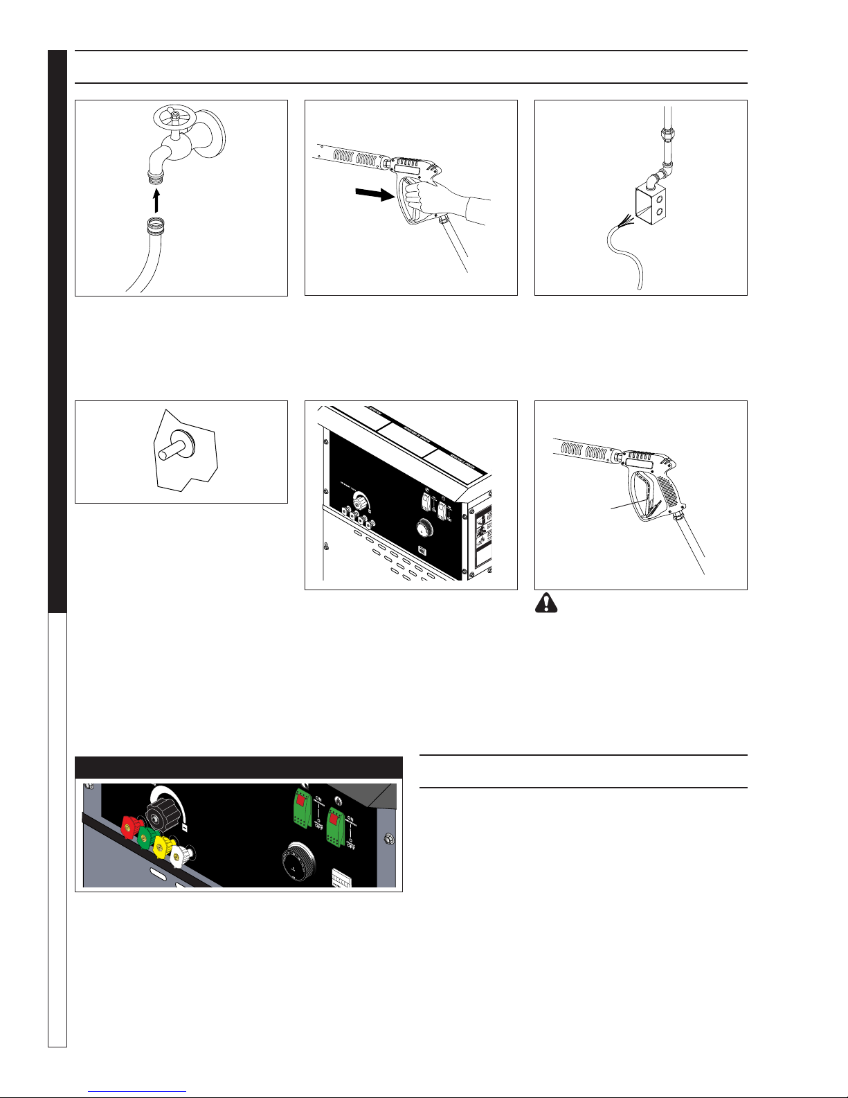
OPERATING INSTRUCTIONS
Cold
Water
Source
Garden
Hose
STEP 1: Review installation instruc-
tions prior to connecting garden
hose to the cold water source and
turn water on completely . Ne ver use
hot water .
OPERATOR’S MANUAL
STEP 4: Depress control knob and
hold it in. After 5 seconds, depress
the red ignitor until you hear a loud
click. Repeat 3 or 4 times if necessary until pilot is lit. If pilot does not
remain lit, repeat operation, allowing a longer period of time before
releasing the knob. After the pilot
lights, continue to hold the control
knob down for 1 minute. Note: Sufficient time must be allowed for a
proper size pilot flame to heat the
thermocouple and hold the safety
magnet in a locked-up position.
STEP 2: Trigger the spray gun to
eliminate trapped air then wait for a
steady flow of water to emerge from
the spray nozzle.
STEP 5: Turn gas cock dial to “PILOT” position.Release dial and turn
to full ON. Push pump s witch ON, or
turn to pump position and pull the
trigger on the spray gun allowing
cold water to flow . T o activ ate the gas
control valve f or hot water , push the
burner switch to the ON position and
pull the trigger on the spray gun.
STEP 3: Have an electrician connect
power supply into junction box according to information shown on the
serial plate before turning gas valve
dial to “pilot” position.
Safety
Latch
WARNING! Never replace
nozzles without engaging the
safety latch on the spray gun trigger.
NOZZLES
The five color-coded quick connect nozzles provide a
wide array of spra y widths from 0° to 45° and are easily
accessible when placed in the conv enient rubber nozzle
holder, which is provided on the front of the machine .
NOTE: For a more gentle rinse, select the white 40° or
green 25° nozzle. To scour the surface, select the yellow 15° or red 0° nozzle. To apply detergent select the
14
black nozzle.
AUTO IGNITION OPTION
If your machine has A uto Ignition option,
follow these steps.
1. Have electrician connect power supply into junction box according to information shown on serial
plate and open main gas supply.
2. Push pump switch to “ON” position, pull trigger on
spray gun.
3. After water and pressure is e xiting pressure nozzle
push burner switch “ON”.
be set at 200°.
4. The pilot will ignite first then you will notice a flash
of light indicating complete ignition.
should hear a clicking sound before the pilot
ignites.
97-610, 97-6152 • REV. 4/04
Note: thermostat should
Note: You
Page 15

DETERGENTS AND GENERAL CLEANING TECHNIQUES
PRESSURE WASHER
WARNING
WARNING: Some detergents
may be harmful if inhaled or ingested, causing severe nausea,
fainting or poisoning. The harmful elements may cause property
damage or severe injury .
STEP 1: Use detergent designed
specifically for pressure washers.
Household detergents could damage the pump. Prepare detergent solution as required by the manufacturer. Fill a container with pressure
washer detergent.
STEP 2: Place siphon tube strainer
into detergent container open detergent valve . Place the filter end of detergent suction tube into the detergent container.
Detergent
Valve
Siphon
Strainer
STEP 3: Pull trigger to operate
machine. Liquid detergent is
drawn into the machine and
mixed with water. Apply detergent to work area. Do not allo w
detergent to dry on surface. Follow operating instructions.
IMPORTANT: You must flush
the detergent siphoning system after each use by
placing the suction tube into a bucket of clean water, then run the pressure washer for 1-2 minutes.
CLEANING TIPS
Pre-rinse cleaning surface with fresh water. Place detergent suction tube directly into cleaning solution and
apply to surface at low pressure (for best results, limit
your work area to sections approximately 6 f eet square
and always apply detergent from bottom to top). Allow
detergent to remain on surface 1-3 minutes. Do not allow detergent to dry on surface. If surface appears to
be drying, simply wet down surface with fresh water. If
needed, use brush to remove stubborn dirt. Rinse at
high pressure from top to bottom in an even sweeping
motion keeping the spray nozzle approximately 1 foot
from cleaning surface. Use overlapping strokes as y ou
clean and rinse any surface. For best surf ace cleaning
action spray at a slight angle.
Recommendations:
• Before cleaning any surface, an inconspicuous
area should be cleaned to test spray pattern and
distance for maximum cleaning results.
• If painted surfaces are peeling or chipping, use
extreme caution as pressure washer ma y remove
the loose paint from the surface.
• Keep the spray nozzle a saf e distance from the surface you plan to clean. High pressure w ash a small
area, then check the surface f or damage. If no damage is found, continue to pressure washing.
CAUTION - Never use:
• Bleach, chlorine products and other corrosive
chemicals
• Liquids containing solvents (i.e., paint thinners,
gasoline, oils)
• Tri-sodium phosphate products
• Ammonia products
• Acid-based products
These chemicals will harm the machine and will damage the surface being cleaned.
RINSING
It will take a few seconds f or the detergent to clear. Apply
safety latch to spray gun. Select and install desired high
pressure nozzle. NOTE: You can also stop detergent
from flowing by removing detergent siphon tube from
bottle.
OPERATOR’S MANUAL
THERMAL PUMP PROTECTION
If you run your pressure washer f or 3-5 minutes without
pressing the trigger on the spray gun, circulating water
in the pump can reach high temperatures. When the
water reaches this temperature, the pump protector engages and cools the pump by discharging the warm
water onto the ground. This thermal device pre vents internal damage to the pump.
15
97-610, 97-6152 • REV. 4/04
Page 16

SHUTTING DO WN AND CLEAN-UP
STEP 2: Tur n/push bur ner
switch to "OFF" position.
Open spray gun allowing
water to cool. Then turn/
push pump switch to “OFF”
position.
PRESSURE W ASHER
STEP 1: Remove detergent suction
tube from container and insert into
one gallon of fresh clean water. Pull
trigger on spray gun and siphon water for one minute.
OPERATOR’S MANUAL
STEP 3: Turn off water
supply.
STEP 4: Press trigger to release water
pressure.
STORAGE
CAUTION: Always store your pressure
washer in a location where the temperature
will not fall below 32°F (0°C). The pump in
this machine is susceptible to permanent damage
if frozen. FREEZE DAMAGE IS NOT COVERED BY
WARRANTY.
1. Stop the pressure washer , squeeze spra y gun trigger to release pressure.
2. Detach water supply hose and high pressure hose.
Safety
Latch
STEP 5: Engage
the spray gun saf ety
lock.
3. Turn on the machine for a few seconds, until remaining water exits. Turn off immediately .
4. Do not allow high pressure hose to become kinked.
5. Store the machine and accessories in a room which
does not reach freezing temperatures.
CAUTION: Failure to follo w the above directions will
result in damage to your pressure washer.
16
97-610, 97-6152 • REV. 4/04
Page 17

BASIC FACTS
o
06nodesaB
UTB000,1xorppAGN.tF.uC1
alumroF 8H3C01H4C
o
)F7.34-1.13
(tnioPnoitaziropaV
)ropaV(ytivarGcificepS 225.1600.2
enaporPenatuB
PRESSURE WASHER
)diuqiL(ytivarGcificepS 805.0485.0
)diuqiL(.laGrep.sbL 32.478.4
)ropaV(.tF.uCrepUTB 365.293.3
)diuqiL(.laGrepUTB 745.19230.201
)diuqiL(.bLrepUTB 195.12122.12
)diuqiL(.bLrep.tF.uC 706.835.6
)diuqiL(.laGrep.tF.uC 54.638.13
rebmuNenatcO 52119
thgieWraluceloM 90.4421.85
:tsoCgninnuRetaluclaCoT.tF.uC1=UTB000,1
mrehT1=.tF.uC001
ruoH1=mrehT1
nuRottsoC=mrehTrepsaGfotsoC
saGlarutaNgnisUelpmaxE
:mrehT¢05ta
enihcaMUTB000,004
OPERATOR’S MANUAL
.tF.uC004
)000,1/000,004(
nuRotruoH/00.2$=¢05x4
sagfotsocx)001/004((
)
PRESSURE EQUIVALENTS
Simply stated, pressure is the force ex erted by a gas or liquid attempting to escape from a container. It is useful
to know how strong this “attempt to escape” is. Pressure can be measured with a manometer or with a pressure
gauge. At the lower lev els, it is e xpressed in “water column inches” i.e . 11 w .c.i. Higher pressures are expressed
in terms of the force ex erted against a square inch of area, for example, 125 lbs. per square inch (125 psi).
hcninmulocretaw1=.ni.qs/.zo05sehcninmulocretaw11= .ni.qs/.zo53.6
sehcninmulocretaw11=.ni.qs/.bl4.ni.qs/.bl1= sehcninmulocretaw17.72
.ni.qs/.bl1=yrucreM"40.2yrucreM"1= ni.qs/.bl93.
erehpsomtA.dtS1=.ni.qs/.sbl37.41
97-610, 97-6152 • REV. 4/04
17
Page 18

TROUBLESHOOTING
PROBLEM POSSIBLE CAUSE SOLUTION
NO SPARK - NO
PILOT GAS
SPARK - BUT NO
PILOT LIGHT
PILOT GAS - BUT
NO SPARK
PILOT LIT - BUT
MAIN BURNER
WON'T COM E ON
PILOT CYCLES
OFF AND ON BY
ITSELF
MAIN BURNER
SHUTS DOWN
PRESSURE WASHER Troubleshooting Guide
LOW OPERATING
PRESSURE
LOW WATER
TEMPERATURE
No main power Restore power.
Faulty limit switch Test/replace.
Faulty wiring Test wiring.
No gas supplied to pilot valve Check for availability of gas.
Manual valves in "OFF" posi tion Turn manual valve and ga s cock to full " ON". Check pilot key
Faulty pilot valve Test gas valve.
Faulty wiring Test wiring.
Restricted p ilot line or clogged pilot orifice Clean pilot tubing and orifices.
Broken or shorted electr od e ass embly Test/replace.
Faulty wiring Test wiring.
Low pilot flame Check inlet pressure, pilot oriface.
Improper alig nment o f sensor in p i lot flame Adjust align ment - see figure 6, pag e 15.
Faulty main gas operator in gas control Test gas valve - repair/replace.
Faulty flame sensor Test sensor, wiring - repair /rep lace.
Faulty pilot valve Test gas valve.
Faulty wiring Test wiring.
Low pilot flame Check inlet pressure, pilot oriface.
Improper alig nment o f sensor in p i lot flame Adjust align ment - see figure 6, pa ge 1 5.
Faulty main gas operator in gas cont rol Test ga s valve - repair/r epl ace.
Faulty flame sensor Test sensor, wiring - repair /rep lace.
Faulty pressure gauge Install new gau ge.
Insufficient water suppl y Use larger garden hose. Clean filter washer at water inl e t.
Old, worn or incorrect s pr ay nozzl e Match nozzle number to machine a nd/ or r ep l ace w i th new
Belt slippage Tighten or replace. Use correct belt.
Plumbing or hose lea k Check plumbing system for leaks. Retape leaks with tef lon
Faulty or misadjusted u nloader valve (where
applicable)
Worn packing in pump Install new packing kit.
Fouled or dirty inlet or discharge valves in
pump
Worn inlet or dischar ge valves Replace with valve kit.
Obstructio n in spr ay nozzle Remove obstruction.
Leaking pressur e contr ol valve (where
applicable)
Detergent meter i ng valve lef t open sucking air
or faulty metering valve
Slow motor RP M Ch e ck i n comin g voltag e.
Improper size of gas li nes See page 8 for sizing of gas l ines.
Low gas pressure Increase gas p ress ur e to machine.
Improper pressure re gula tor Specify BTU, building gas pressur e 11 w.c.i. to machine for
Low gas pressure Increase gas p ress ur e as describe d on page 10.
Soot buildup on coi l s no t allowing heat
transfer
Improper burner no zzle
adjustment.
nozzle.
tape.
Adjust unloader for prope r pres sur e. Install repai r kit whe n
needed.
Clean inlet and d ischa rge valve.
Rebuild or replace as needed.
Close and/or repla ce meter ing valve.
correct sizin g of regul ator.
Clean coils.
See serial plate.
18
97-610, 97-6152 • REV. 4/04
Page 19

TROUBLESHOOTING
MELBORPESUACELBISSOPNOITULOS
RETAW
ERUTAREPMET
TOHOOT
FOECNESERP
LIONIRETAW
GNIPPIRDRETAW
REDNUMORF
PMUP
TONTNEGRETED
GNIWARD
GNINNURPMUP
TUBYLLAMRON
WOLERUSSERP
NOITALLATSNINO
GNITAUTCULF
ERUSSERP
YSIONPMUP
GNIPPIRDLIO
EVISSECXE
NINOITARBIV
ENILYREVILED
EVLAVFEILER
RETAWSKAEL
nrowlaesliO .yrassecenfiecalperdnakcehC
kaelriA .selohrofseniltnegretedkcehC.spmalcllanethgiT
nrowgnikcap
deggulp
)elbacilppa
nrowsevlaV .yrassecenfiecalperdnakcehC
sgnirps
nrowlaesliO .yrassecenfiecalperdnakcehC
hgihooterusserpsaG .erusserpsagreporprofsnoitacificepsrof01egapeeS
riagnikcuseniltnegreteD .selohrofseniltnegretedkcehC.spmalcllanethgiT
hctiwstimilhgihevitcefeD.ecalpeR
eziselzzonrenrubtcerrocnI.etalplaireseeS
deilppusretawtneiciffusnI .enihcamotMPGretawkcehC
wolfretawdetcirtseR .ezisreporp,noitcurtsborofelzzonkcehC
rianiytidimuhhgiH .netfosaeciwtlioegnahcdnakcehC
nrowgnikcapnotsiP .yrassecenfiecalperdnakcehC
nrowreniaterregnulpgniR-O .yrassecenfiecalperdnakcehC
tnegretedfoytisocsivhgiH .snoitacificepsottnegretedetuliD
)s(eniltnegretednieloH.elohriapeR
deggulpteksabreniartS.naelcdnaevomeR
riagnikcuspmuP .egapeesriafoytilibissopdnaylppusretawkcehC
gnikcitssevlaV .yrassecenfiecalperronaelcdnakcehC
ytluaftaesevlavredaolnU .yrassecenfiecalperdnakcehC
dezisyltcerrocnielzzoN rofetalplaireseeS(yrassecenfiecalperdnakcehC
gnikcapnotsipnroW .yrassecenfiecalperdnakcehC
evlavniegakcolB .yrassecenfiecalperdnakcehC
riagnikcuspmuP nistniojtaegapeesriadnaylppusretawkcehC
gnikcapnotsipnroW .yrassecenfiecalperdnakcehC
enilnoitcusniriA .enilnoitcusnosnoitcennocdnaylppusretawkcehC
sevlavnirettamevissecxE .yrassecenfinaelcdnakcehC
sgniraebnroW .yrassecenfiecalperdnakcehC
evitcefedevlavfeileR.riaperroecalpeR
tohromrawenihcamotretawgnimocnI .erutarepmetretawgnimocnirewoL
esohnoitcustnegretednoneercsretliF
esoolevlavrotcelesnosnoitcennoC .snoitcennocepipllanoepatnolfettuP
erehw(gninepotondionelostnegreteD
evlavegrahcsidrotelnikaewronekorB
sevlavehtfogninoitcnufralugerrI .yrassecenfiecalperdnakcehC
rothgittongnikcapevlavgniretemtnegreteD
evlavgniretemgniggulptnegretedpudeirD .ylhguorohtnaelcdnaelbmessasiD
devomerneercsknattaolfdnihebnoitcirtseR.noitcirtserllatsnI
PRESSURE WASHER Troubleshooting Guide
.gnikcaproevlavecalpeR.tunnethgiT
.ecalperronaelC
.dionelostnegretedecalper,hctiwswolfkcehC
.)ezisreporp
.enilnoitcus
.yrassecenfiecalperdnakcehC
19
97-610, 97-6152 • REV. 4/04
Page 20

MAINTENANCE & SERVICE
Spray Nozzles:
Each machine is equipped with one or more spray
nozzles, depending on the model. Different spray
nozzles are calibrated for each machine, depending on
the flow and pressure of that particular model. Spray
nozzles vary in bore size and angle of spray. Popular
spray angles are 0°, 15°, 25°, 40°. When ordering, please
specify size and angle of nozzle. Nozzle size for each
machine is located on the serial plate.
Unloader V alves:
Unloader valves relie ve pressure in the line when a spray
gun is closed. Unloader v alves are preset and tested at
the factory before shipping. Occasional adjustment of
the unloader may be necessary to maintain correct pressure. For valv e adjustment contact y our nearest dealer
or call technical support.
Winterizing Procedure:
Damage due to freezing is not covered by warranty.
Adhere to the following cold weather procedures whenever the washer must be stored or operated outdoors
under freezing conditions.
PRESSURE WASHER Troubleshooting Guide
It is necessary to protect your machine against freezing when temperatures drop below 32° F. Siphoning a
small amount of antifreeze into the system is recommended. This is done by pour ing a 50-50 mix of antifreeze and water into the float tank and then siphoning
100% antifreeze through the detergent line with the
pump on. If compressed air is available, an air fitting
can be screwed into the float tank strainer fitting, and
by injecting compressed air , all w ater will be blo wn out
of the system. The use of a draft diver ter will prevent
the wind chill factor from freezing the coil.
Low Pressure Diagnosis:
(Machines with spray gun)
Refer to Troubleshooting Chart for low pressure. If the
trouble is found to be either the unloader or the pump ,
your next step is to determine which is the problem.
This can be done by eliminating the unloader from the
system and attaching the 50' discharge hose directly to
the pump. If high pressure is dev eloped in this manner ,
the pump is good and the unloader needs to be repaired
or replaced. If low pressure is still present, then the pump
needs repairing.
CAUTION: When using this procedure to test components keep the spray gun open at all times.
High Limit Hot Water Thermostat:
For safety, each machine is equipped with an adjustable thermostat. In the e vent the temperature of the w ater should exceed its operating temperature, the thermostat will turn the burner off until the water cools.
20
97-610, 97-6152 • REV. 4/04
Pumps:
Use only SAE30 weight non-detergent oil. Change oil
after first 50 hours of use. Thereafter , change oil e v ery
three months or at 500 hour intervals. Oil level should
be checked through use of the dipstic k found on the top
of the pump or by the red dot visible through the oil
gauge window . Oil should be maintained at that level.
HEATING COILS
To Check Water Heater Coil for Leaks:
With the main burners "OFF" start the pumping unit and
allow it to run for a few minutes. With a drop light or
flashlight, check the burner compartment. If no leaks
are visible and water is dripping from the coils, then it is
condensation from the flue gases when the burners are
on.
Condensation from Heating Coil:
When cold water is being pumped into the water heater
coils and the burners are on, condensation will form on
the coils and drip down into the burner compartment.
This will give the appearance of a leaking coil, particularly on cold humid days.
Deliming Coils:
In alkaline water areas, lime deposits can accumulate
rapidly inside the coil pipes. This gro wth is increased by
the extreme heat build up in the coil. The best prevention for liming conditions is to use high quality cleaning
detergents. In areas where alkaline water is an extreme
problem, periodic use of Manufacturers Deliming P o wder (part #9-028008) will remove lime and other deposits before coil becomes plugged. (See following Instructions for use of Deliming P o wder .)
Periodic flushing of coils is recommended.
1. Fill a container with 4 gallons of water, then add 1
lb. of deliming po wder. Mix thoroughly .
2. Remove nozzle from spray gun assembly and put
spray gun into container. Secure the trigger on the
spray gun into the open position.
3. Attach a short section (3-5 ft.) of garden hose to
machine to siphon solution from an elevated container, or add mixture to the float tank. Tur n pump
switch on allowing solution to be pumped through
coils and back into the container. Solution should
be allowed to circulate 2-4 hours.
4. After circulating solution, flush entire system with
fresh water. Reinstall w and assembly to spray gun.
Page 21

MAINTENANCE & SERVICE
PRESSURE WASHER Troubleshooting Guide
Gas Valve Regulator Adjustment:
(See Fig. 5)
Adjustment of the built-in regulator isn’t normally necessary, since it is preset at the factory. However, field
adjustment may be accomplished as follo ws:
1. Attach manometer at both inlet and outlet pressure
ports.
2. Remove manifold pressure adjustment scre w cap .
3. With small screwdriver, rotate manifold pressure adjustment screw clockwise to increase or counterclockwise to decrease gas pressure.
4. Replace manifold pressure adjustment screw cap .
Figure 5
Control
Knob
Inlet
View
Pressure
Inlet
Port
Line to
Pilot Light
Outlet
Pressure
Pilot Key
Adjustment
Gas Valve Adjustment
Manifold Pressure
Adjustment Screw
Under Cap
Outlet
View
Port
Pilot Burner Adjustment:
1. Remove pilot adjustment cap.
2. Adjust pilot key to provide properly sized flame.
3. Replace pilot adjustment cap.
Rupture Disk:
If pressure from pump or if thermal expansion should
exceed safe limits, the rupture disk will burst, allowing
high pressure to be discharged through hose to ground.
When the disk ruptures, it will need to be replaced.
Torque to 35 ft. lbs.
PROPANE GAS (Vapor Fuel Only)
General Safety Precautions:
Have a qualified gas service person assist in any gas
burner installation or service. Fe w maintenance people
or mechanics are knowledgeable in gas controls or related safety practices. Since propane gas is heavier than
air, unb urned propane gas will gravitate to the floor rather
than rise out of the stack. Hence , adequate floor space
and good ventilation are especially important with propane systems.
Gas Pressure Requirements:
All propane fired machines operate on gas phase only .
They are designed to operate at a pressure of 11 w .c.i.
(between 1/3 and 1/2 of one PSI), and are often operated at even higher pressures when extra heat is
needed.
Exterior regulators are needed to control the system.
Propane bottles are not included with the machine. A
high pressure regulator should be installed on the propane bottle and a low pressure regulator attached to
the pressure washer.
Propane Cylinder Capacity:
An important consideration with propane systems is the
capacity of the supply cylinder relative to the needs of
the burner. The burner operates on propane as a gas.
As gas is used from the propane cylinder, the liquid in
the cylinder boils to maintain gas pressure. This boiling
process cools the liquid, and in a heavy, continuousdemand situation, the liquid temperature can fall to the
point at which it cannot provide gas as rapidly as is
needed. In this case , it may be necessary to warm the
propane cylinder by directing a warm spray, not over
120°, on the cold cylinder, or by manifolding two propane bottles together to increase total vaporization capacity. It is recommended that a minimum 100 lb. propane bottle be used on the machine, depending on the
length of running time desired.
BURNER FEATURES
Operated Automatic Valve:
This machine is equipped with a thermopile self-powered combination gas control. This system is designed
as a constant burning pilot. Lighting of the pilot is accomplished by manually lighting the pilot. A thermostat
and flow switch control the main solenoid v alv e.
Care of Main Burner:
Because of condensation from the heater coils dripping
down on the burners, scale buildup may occur in the
burner jet orifices.
1. TO REMOVE BURNER MANIFOLD FROM
WATER HEATER COIL:
Tur n off the gas at the main burner by tur ning the
knob to the “OFF” position on the gas valve and
main gas supply.
21
97-610, 97-6152 • REV. 4/04
Page 22

MAINTENANCE & SERVICE
Disconnect the pilot and ignition lines from the gas
valve. Disconnect union in main burner line. (Remove the nuts from the U-bolts, item 21 on page
24). Slide b urner manifold out through shell open-
ing.
2. TO CLEAN B URNER JETS:
Select proper size drill for type of gas inv olved. Use
vise to hold drill and to ream out each jet orifice.
If the water heater will be exposed to freezing weather ,
an antifreeze solution should be circulated through the
coils by whatever means are a vailable f or the particular
system the water heater is used on.
BURNER TROUBLESHOO TING
Millivolt System Check:
This machine has a thermopile self-powered combination gas control. Before checking the millivolt system,
the following operations should be performed and observations made:
1. Inspect system for proper wiring.
PRESSURE WASHER Troubleshooting Guide
2. The switch leads and all wire connections should
be cleaned and tightened to eliminate all unnecessary resistance.
3. Clean and/or adjust pilot for maximum flame impingement on the thermopile.
4. If pilot will not remain lit when gas cock dial is released, check automatic pilot (Step D).
TERM
TH
TH
TP
TERM
The millivolt system and individual components may be
checked with a DC milliv olt meter having a 0-1000 MV
range. Conduct each check as shown in the chart below by connecting the meter test leads to terminals as
indicated. All readings are closed circuit.
A. Complete Millivolt System Chec k
(“A” Reading = Switch contacts CLOSED - Gas
Cock Dial “ON” - Main burner should come ON).
1. If the reading is more than 100 millivolts and the
automatic valve still does not come on, replace
the automatic valve operator.
2. If the closed circuit reading (“A” Reading) is less
than 100 millivolts, determine cause for low reading - proceed as follows:
B. Thermopile Output Reading Check
(“B” Reading = Switch contacts OPEN - Main burner
OFF).
If the minimum 250 millivolt reading is not obtainable, readjust pilot for maximum milliv olt output. If millivolt reading is still below minimum
specified, replace thermopile.
2 Lead Thermopile
Equivalent
To (CP-2)
To Burner
Flow Switch
Igniter
Pilot 2CH-2
or
Equivalent
22
MILLIVOLT
Check
Test
A
B
C
D
TERMINAL
Complete
Thermopile
Resistance
Auto/Pilot
OPERATOR
PANEL
To Test
System
Output
System
Dropout
TP
Connect
Meter
Leads To
Terminals
2 & 3 Cl osed
1 & 2 Open
1 & 3 Closed
1 & 2 Open
Switch
Flow &
Burner
Contacts
TERM
Meter
Reading
Should
Be
100 MV or
More
Greater
than 250
Less than
35
Between
120 - 30
MV
97-610, 97-6152 • REV. 4/04
2 Lead
Thermopile
Connections
Gas
Valve
Page 23

MAINTENANCE & SERVICE
PRESSURE WASHER Troubleshooting Guide
C. System Resistance Check
(“C” Reading = Switch contacts CLOSED - Gas
Cock “ON” - Main burner should be ON)
If the “C” Reading is more than that specified
for the system being checked, this indicates the
resistance in the system is excessive and must
be reduced. To correct:
a. Clean and tighten switch leads and connec-
tions.
b. Shorten switch lead wires and/or replace
with heavier gauge wire.
c. Cycle switch r apidly to clean contacts .
D. Automatic Pilot Dropout Check
1. Hold gas cock dial depressed in pilot position
until maximum output is observed. Then extinguish pilot and observe meter.
2. Dropout of automatic pilot magnet (sound should
be audible) should occur between 120 millivolts
and 30 millivolts. If dropout occurs outside these
limits, change the automatic pilot magnet assembly.
23
97-610, 97-6152 • REV. 4/04
Page 24

PREVENTATIVE MAINTENANCE
This pressure washer was produced with the best availab le materials and quality craftsmanship. Howe ver , you as
the owner have certain responsibilities for the correct care of the equipment. Attention to regular preventative
maintenance procedures will assist in preserving the performance of your equipment. Contact your TUFF, Inc.
dealer for maintenance. Regular prev entative maintenance will add many hours to the life of y our pressure washer .
Perf orm maintenance more often under severe conditions .
ELUDEHCSECNANETNIAM
seniLleuFecalpeRyllaunnA
liOpmuP
retliFrenruBnaelCyllaunnA
noisneTtleBkcehCylhtnoM
lioCelacseD )deriuqerfinetfoerom(-yllaunnA
PRESSURE WASHER Troubleshooting Guide
esoHPHecalpeRraewfongisynasierehtfI
rotoMesaerGsruoh000,01yrevE
evlaVfeileRerusserPyllaunnA
tcepsnIlevellioehttcepsniyliaD
egnahCyllaunnarosruoh005yreveneht,sruoh05tsrifretfA
lioCgnitaeHmorFtooSrenruBevomeRyllaunnA
elzzoNerusserPhgiHecalpeRshtnom6yrevE
stcennoCkciuQecalpeRyllaunnA
retliF/neercStnegreteDdnaretaWnaelCylkeeW
knaTylppuS/taolFnaelCshtnom6yrevE
steJtoliPrenruBkcehCyllaunnA
24
OIL CHANGE RECORD
degnahCliOetaD
raeY/yaD/htnoM
97-610, 97-6152 • REV. 4/04
sruoHgnitarepOdetamitsE
egnahCliOtsaLecniS
Page 25

PRESSURE WASHER
HOSE & SPRAY GUN ASSEMBLY
5
4
3
HOSE & SPRAY GUN PARTS LIST
ITEM PART NO . DESCRIPTION QTY
1 2-2002 Coupler, 3/8" Female 1
2 4-020650C Hose 3/8" x 50', 1 Wire Pressure
Flex w/Coupler 1
4-02093450BC Hose, 3/8” x 50’, 1 Wire Blue,
w/Coupler 1
3 4-01246
4 4-0111021 Lance, Spray, Insulated 1
5 4-12805500 Nozzle, SAQCMEG 0005.5
4-12805515 Nozzle, SAQCMEG 1505.5
4-12805525 Nozzle, SAQCMEG 2505.5
4-12805555 Nozzle, SAQCMEG 4005.5
4-12805000 Nozzle, SAQCMEG 0005
Spray Gun, Shut-Off AP-1000
Red (5030, 3010, 4020) 1
Yellow (5030, 3010, 4020) 1
Green (5030, 3010, 4020) 1
White (5030, 3010, 4020) 1
Red (3520) 1
1
1
2
ITEM PART NO . DESCRIPTION QTY
5 4-12805015 Nozzle, SAQCMEG 1505
Yellow (3520) 1
4-12805025 Nozzle, SAQCMEG 2505
Green (3520) 1
4-12805040 Nozzle, SAQCMEG 4005
White (3520) 1
4-12807000 Nozzle, SAQMEG 0007
Red (5020) 1
4-12807015 Nozzle, SAQMEG 1507
Yellow (5020) 1
4-12807025 Nozzle, SAQMEG 2507
Green (5020) 1
4-12807040 Nozzle, SAQMEG 4007
White (5020) 1
4-12804000 Nozzle, SAQCMEG 0004
Red (3530) 1
4-12804015 Nozzle, SAQCMEG 1504
Yellow (3530) 1
4-12804025 Nozzle, SAQCMEG 2504
Green (3530) 1
4-12804040 Nozzle, SAQCMEG 4004
White (3530) 1
OPERATOR’S MANUAL
25
97-610, 97-6152 • REV. 4/04
Page 26

73
PRESSURE W ASHER
74
OPERATOR’S MANUAL
79
78
13
12
14
75
76
74
EXPLODED VIEW
99
77
72
For
Detail See
Burner
Assembly
Illus.
71
85
68
69
67,86
66
Detergent
65
For
Detail See
Burner
Assembly
Illus.
100
To
Valve
70
92
56
89
57
51,53
87
Detail See
Float T ank
55
For
Pg. 31
88
87
35
88
48
50
49
87
6
52
35
36
58
26
81
80
82
For
Detail See
Control
Panel Pg.
34
Steam
Valve
Option
52
26
61
62
63
Steam
Valve
Option
83
84
6
97-610, 97-6152 • REV. 4/04
59
64
Page 27

47
EXPLODED VIEW
46
PRESSURE WASHER
6
52
5 GPM
Machines
42
26
58
301007,
352007
Models
24
41
Only
37
34
38
44
35
36
33
27
32
43,98
13
30
97
28
28
29
22
45
Steam
Valve
Option
27
60
25
21
OPERATOR’S MANUAL
19
28
13
26
12
14
62
23
17
18
20
24
40
Steam
Valve
39
8
Option
95
94
93
9
10
90
97
15
96
11
97
11
91
91
97
91
For Detail
Electrical Box
Pg. 36
97-610, 97-6152 • REV. 4/04
See
50
1
2
6
4
3
6
27
Page 28

EXPLODED VIEW PARTS LIST
ITEM PART NO. DESCRIPTION QTY
1 95-07163028 Box, Electrical 1
2 95-07163113 Panel, Front 1
3 95-07163114 Cover, E-Box Access 1
4 10-07994 Label, Warning 1
6 90-19711 Screw, 1/4" x 1/2" HH NC,
Whiz Loc 42
PRESSURE W ASHER
8 95-07163119 Brace, Panel 1
9 95-071210136 Platform, Motor 3/16" (3520,
28
95-07121013 Platform, Motor, 3 GPM
10 95-07121112 Rail, Pump or Generator Combo
95-07163136 Rail, Pump, Legacy Pumps
11 90-2007 Nut, 3/8" Hex, NC 3
OPERATOR’S MANUAL
12 90-4002 Washer, 3/8" SAE, Flat 22
13 90-2002 Nut, 3/8", ESNA, NC 14
14 90-4007 Washer, 3/8" x 1-1/2", Fender,
15 90-1025 Bolt, 3/8" x 5-1/2", Tap 2
16 90-2020 s Nut, Cage, 3/8" x 12 GA 8
17 5-511075 Bushing, H x 3/4" (3520) 1
5-511113 Bushing, H x 1-1/8" (4020) 1
5-511138 Bushing, H x 1-3/8"
18 5-512024 Bushing, H x 24mm 1
19 5-40102858 Pulley, Bore, AK 28 x 5/8"
5-40102558 Pulley, AK 25 x 5/8" (301007) 1
5-40203201 Pulley, 2AK 32 H (352001) 1
5-40204901 Pulley, 2AK 49 H (502001) 1
5-40506001 Pulley, 2BK 60 H (502007,
5-40205401 Pulley, 2AK 54 H (402001,
5-40203001 Pulley, 2AK30H (352007) 1
5-40504501 Pulley, 2BK 45 H (353001,
5-40505701 Pulley, 2BK 57 H (503001) 1
20 5-40108401 Pulley, AK 84 H (301001,
5-40206401 Pulley, 2AK 64 H (502001) 1
5-40207401 Pulley, 2AK74H (402007) 1
5-40208401 Pulley, 2AK 84 H (402001,
5-40506701 Pulley, 2BK 67 H (353007, 502007,
5-40507001 Pulley, 2BK 70 H (503001) 1
5-40508001 Pulley, 2BK 80 H (353001) 1
4020, 5020, 3530, 5030) 1
(3010) 1
(301001, 3520, 4020, 5020, 3530,
5030) 1
(301007) 1
SAE 14
(3530, 5020, 5030) 1
(301001) 1
503007) 1
402007) 1
353007) 1
301007) 1
352001, 352007) 1
503007) 1
ITEM PAR T NO. DESCRIPTION QTY
21 5-604035 Belt, BX35 (502007) 2
5-604036 Belt, BX36 (503001, 353001) 2
5-602034 Belt, AX34 (352007, 502001) 2
5-602036 Belt, AX36 (301007) 1
(402007) 2
5-602038 Belt, AX38 (301001) 1
5-604035 Belt, BX35 (503007, 502007) 2
5-602037 Belt, AX37 (352001, 402001) 2
5-604032 Belt, BX32 (353007) 2
22 5-2302 Pump, General, T-991 (301001)1
5-2304 Pump General, T-1011
(402001) 1
5-23040 Pump, General, TS-1011
(352001) 1
5-2307 Pump, General, TS-2021
(353001, 502001, 503001) 1
5-1625 Pump, Legacy WML-2540
(301007, 352007) 1
5-1651 Pump, Legacy, TML-3053
(402007, 502007, 353007,
503007) 1
23 1-190029 Cap, Valve, with 1/4" Gauge Port
(301001, 352001, 402001,
353001, 502001, 503001) 1
15-070042532 Cap, Valve, with 1/4" Gauge
Port, Legacy (301007, 402007,
502007, 353007, 503007,
352007) 1
24 2-300816 Pump Protector, 3/8" PTP
(301007, 352007) 1
2-30082 Pump Protector, 1/2" (All except
301007, 301607, 352007) 1
25 6-021720 Switch, Pressure N/O,
1/4" NPT SS 1
26 2-1042 Tee, 1/2" Street 2
(5 Gpm) 3
27 2-1076 Bushing, Reducer, 1/2" x 1/4" 1
28 2-1089 Hose Barb, 1/4" Barb x 1/4" Pipe,
90° 1
(w/Steam Option) 2
29 2-9000 Clamp, Screw, #4 3
30 2-1037 Tee, 1/4" Branch Male
(Steam Option) 1
32 2-0051 Nipple, 1/2" JIC, 3/8" Pipe 1
33 2-0079 Swivel, 1/2" JIC Fem., 3/8"
Male 1
34 2-10712 Tee, 1/2" x 1/2" JIC 51#
(All except 5020, 5030) 1
35 2-1105 Swivel, 1/2" JIC Fem, Push-On 4
(5020, 5030) 2
2-11050 Swivel, 3/4" SAE Fem, Push-On
(5020, 5030) 2
36 4-02110000 Hose, 1/2", Push-On 3 ft.
4-02120000 Hose, 3/4", Push-On
(5020, 5030) 3 ft.
97-610, 97-6152 • REV. 4/04
Page 29

EXPLODED VIEW PARTS LIST
PRESSURE WASHER
ITEM PAR T NO. DESCRIPTION QTY
37 5-3208 Unloader, AL-VRT 607,
7.8 GPM @ 4200 PSI 1
38 2-106301 Elbow, 1/2" JIC x 3/8", 45° 1
39 2-0031 Elbow, 3/8", Street
(Steam Option) 1
40 2-00682 Bushing, 3/8" x 1/4" Steel
(Steam Option) 1
41 4-02047725 Hose, 3/8" x 25", 2 Wire,
Pressure Loop 1
42 2-0053 Elbow, 1/2" JIC, 3/8", 90° 1
43 5-1047 Motor, 2HP, 1 PH 115/208/230V
3450 RPM (3010D) 1
5-1053 Motor, 5HP 1PH 230V 3450 RPM
(3520A) 1
5-10401 Motor, 6HP 1PH 1725 RPM
(4020A) 1
5-1011 Motor, 6HP 3PH 1725 RPM
(4020B,C) 1
5-1013 Motor, 7.5HP 1PH 1725 RPM
(3530A, 5020A) 1
5-10145 Motor, 7.5HP 3PH 208/230/460
1725 RPM (3530B,C, 5020B,C) 1
5-1018 Motor, 10HP 3PH 230/460V
1725 RPM (5030B,C) 1
44 6-0104 Cord, Electric 12/3 SOWA
(3010D, 3520A) 9.25 ft.
6-0108 Cord, Service, SEO, 10/3
Coleman (4020A) 9.25 ft.
6-0102 Cord, Service, SO, 8/3
Coleman (3530A, 5020A) 9.25 ft.
6-0109 Cord, Service, SEO 10/4
(5020B, 3530B) 9.25 ft.
6-01021 Cord, Service 8/4(5030B) 9.25 ft.
6-0105 Cord, Service 12/4(3530C;
4020B,C; 5020C; 5030C) 9.25 ft.
45 95-07163117Panel, Side, Left 1
46 95-07163116Cover, Top 1
47 10-99075 Label, Operating Instructions 1
48 95-07163102Panel, Rear 1
49 2-0148 Plug, Plastic, 7/8" 1
50 90-2022 Nut, Cage, 1/4" x 16 Gauge 30
51 6-04110 Box, Junction 3 Hole, 3/4" 1
52 2-1062 Elbow, 1/2" JIC x 1/2", 90° 2
(5020, 5030) 1
2-10630 Elbow, 3/4" JIC x 1/2", 90°
(5020, 5030) 2
53 6-0411 Cover Plate, Junction Box,
2" x 4" 1
11-1042 ▲ Ground Label 1
55 4-02100030 Inlet Hose, 30", Water Supply 1
56 4-02100045 Inlet Hose, 45", Water Supply 1
57 2-00602 Elbow, 1/2" JIC x 1/2" Fem, 90°1
97-610, 97-6152 • REV. 4/04
ITEM PAR T NO. DESCRIPTION QTY
58 2-1053 Nipple, 1/2" JIC 1/2" MPT Pipe
(5020, 5030) 2
(All others) 1
59 2-10942 Swivel, 1/2" MP x 3/4" GHF,
w/Strainer 1
60 10-09003 Label, Cold Water Inlet 1
61 2-1100 Adapter, 1/2" x 1/2" Pipe 1
62 2-0108 Bumper Pad, Engine 18
63 2-01041 Pad, Soft Rubber, 50 DURO 6
64 95-07163100Assy, Frame 1
65 2-2007 Nipple, 3/8" x 3/8" NPT ST
Male 1
66 2-00575 Elbow, 3/8" Steel, Street, 45° 1
67 95-07101226Block, Discharge, Brass,
1/2" x 1/2" 1
68 2-3409 Disk, Rupture Assy, 7000 PSI 1
69 2-1108 Hose Barb, 1/2” Barb x 3/8” MPT,
Push-On 1
70 4-05088 Thermostat, Adjustable, 302°F 1
71 2-0008 Nipple 1/2" Hex, Steel 1
72 4-02110000 Hose, 1/2” Push-On 3.33 ft.
73 95-07163099 Top, Burner Wrap, 20" 1
74 10-02025A Label, Hot/Caliente w/Arrows
Warning 2
75 7-01415 Insulation, Tank Head, 20",
10" Opening 1
76 90-50045 Clip, Retaining, U-Type 4
77 95-07121220 Coil, Dura, 20" Dia., SCH. 801
78 95-07163094 Wrap, Outer Assy, 20" Coil 1
79 90-1016 Bolt, 3/8" x 1", NC HH 8
80 95-07163126 Cover, Control Panel, Logo 1
95-07163115 Cover, Control Panel,
Remote 1
81 11-0353 Label, Control Panel, Logo 1
11-0354 Label, Control Panel, Remote
Logo 1
11-0508 Label, Control Panel 1
11-0509 Label, Control Panel, Remote 1
82 95-07163118Panel, Side, Right 1
83 4-02021236 Hose, 1/4" x 36", 2 Wire,
Gauge Hose (Steam Option) 1
84 90-20231 Nut, Cage, 1/4" x 12 Gauge 12
85 2-00681 Bushing, 1/2" x 3/8" Steel 1
86 10-09004 Label, Hot Water Outlet 1
87 2-01411 Bushing, 1" Snap 3
88 2-01081 Plug, Rubber 3
89 2-01037 Grommet, 1-5/16" Rubber 1
90 90-2002 Nut, 3/8" ESNA (3010, 3520) 6
(4020, 3530, 5020) 8
90-2001 Nut, 5/16" ESNA (3010, 3520) 4
OPERATOR’S MANUAL
29
Page 30

EXPLODED VIEW PARTS LIST
ITEM PART NO. DESCRIPTION QTY
91 90-1016 Bolt, 3/8" (3010, 3520) 6
(4020, 3530, 5020) 8
90-1006 Bolt, 5/16" (3010, 3520)
92 10-08021 Label, Disconnect Pwr Supply 1
93 90-1030 Bolt, 8mm x 16mm Hex Head 4
94 90-4008 Washer, 5/16" Lock Split Ring 4
95 90-4001 Washer, 5/16" Flat 4
PRESSURE W ASHER
96 95-07141110 Retainer, Pump Take-Up
97 90-4002 Washer, 3/8" (3010, 3520) 12
90-4001 Washer, 5/16" (3010, 3520) 8
98 6-0517 ▲ Strain Relief, 3/4" (3010;3520
6-05171 ▲ Strain Relief, 1" (3530A;
99 2-1019 Elbow, 3/8” Female 1
OPERATOR’S MANUAL
100 2-00742 Adapter, 1/2” x 1/2” Pipe STL 1
(3010) 8
(4020, 3530, 5020) 16
3530B,C;4020;5020B,C) 1
5020A; 5030B,C;) 1
▲ Not Shown
30
97-610, 97-6152 • REV. 4/04
Page 31

PRESSURE WASHER
FLOA T TANK ASSEMBL Y
4
9
6
10
3
2
8
7
5
1
To Outside
Water
Supply
To Pump
OPERATOR’S MANUAL
ITEM PAR T NO. DESCRIPTION QTY
1 11-0603 Label, TUFF, Stripe 17" 1
2 2-0100379 Adapter, 3/4" x 3/4" MT x Insert,
90° 1
3 2-010058 Bulkhead, 3/4" Polypropylene 1
4 2-01164 Tank, Plastic Universal Float 1
5 2-0151 Plug, Float Tank 1
FLOA T TANK PARTS LIST
ITEM PAR T NO. DESCRIPTION QTY
6 2-1062 Elbow, 1/2" JIC x 1/2", 90° 1
2-1024 Elbow, 1/2" Street (301007) 1
2-10062 Nipple, Modified Close, 3/16 1
7 2-11041 Connector, 1/2" Anchor 1
8 2-1906 Strainer, 1/2" Basket 1
9 2-3014 Valve, Fluidmaster, 400A, Float2
10 4-02120000 Hose, 3/4" Push-On 2 ft.
31
97-610, 97-6152 • REV. 4/04
Page 32

BURNER ASSEMBLY
21
PRESSURE W ASHER
OPERATOR’S MANUAL
15
14
13
10
19
29
20
23
22
31
28
21
25
26
1
2
3
4
5
6
7
9
4
5
16
18
17
5
30
32
12
10
9
11
32
(Elec. Ignition
Only)
97-610, 97-6152 • REV. 4/04
24
(Elec. Ignition
Only)
8
32
4
5
Page 33

BURNER ASSEMBLY PARTS LIST
PRESSURE WASHER
ITEM PART NO . DESCRIPTION QTY
1 7-7021 Jet, Orifice, #54 Natural Gas 44
7-7022 Jet, Orifice, #69 2
2 95-031610/54 Burner Assy, Sq., Small #54 1
95-031610/65 Burner Ring, Small, Square, #65
Nozzles 1
3 2-001359 Bushing, 1" x 3/4", Black, Steel
Hex 1
4 2-00162 Nipple, 3/4" x 3", Black Pipe 3
5 2-00293 Elbow, 3/4", Black, 90° 4
6 2-00164 Nipple, 3/4" x 6", Black Pipe 1
7 2-00163 Nipple, 3/4" x 2", Black 1
8 2-0087 Union, 3/4", Black Pipe 1
9 2-00151 Nipple, 3/4" x Close, Black 2
10 95-07163081Nipple, 1" NPT x 15", Black,
SCH. 40 2
11 2-00295 Elbow, 1" x 3/4", Reducing,
Black 1
12 2-00291 Elbow, 1", Black, 90° 1
13 2-00091 Nipple, 1/2" x 3", Galv. SCH. 801
14 95-0712113 PHW/VNG Insulation Retainer
Plate 1
15 90-2999 Screw, #10 x 1/2", TEK 4
16 95-07163097Cover, Burner Access, 20" Coil 1
17 90-19942 Screw, 10/32" x 3/4", Hex Wash
SL Mach/Blk 2
18 10-99032 Label, Pilot Light Hole 1
10-99077 Label, Pilot Light Warning 1
ITEM PART NO . DESCRIPTION QTY
19 90-2018 Nut, Cage, 10/32" x 16 Gauge 2
20 7-70162 Ignitor, Piezo #1244-42 1
7-70164 Washer, Panel Adapter, Piezo
1244-26 1
21 90-10131 U-Bolt, 5/16" x 3", Pipe 2
22 7-70237 Pilot, Natural Gas Pilot A3-S,
#77623 1
7-7036 Thermopile, 44" MFG 1
23 7-0150 Tubing, Aluminum, 600/Rl, 1/4"
Dead Soft 36
24 7-7000HC Valve, Gas 7000 MVRHC,
#497701404 1
7-70002 Valve, Gas, 7000 DERHC,
#5N2501531 (Elec Ignition) 1
25 2-3006 Valve, Ball, 1/4" Female x 1/4"
Female, UL Listed #12 1
26 2-1118 Connector, 1/4" Tube x 1/4"
MPT 2
27 95-07163085▲ Splash Guard 1
28 90-10130 U-Bolt, 5/16" x 1", Pipe 1
29 10-99077 Label, Pilot Light Warning 1
30 10-02020 Label, Burner Instructions 1
31 10-02024 Label, Natural Gas 1
32 2-001359 Bushing, 1" x 3/4" Black Steel
(Electronic Ignition) 2
▲ Not Shown
OPERATOR’S MANUAL
33
97-610, 97-6152 • REV. 4/04
Page 34

CONTROL PANEL EXPLODED VIEW
7
8
PRESSURE W ASHER
OPERATOR’S MANUAL
10
9
For Internal
Detail See
Electrical Box
Pages 36, 38
& 40
13
Steam
12
11
Valve
Option
15
10
3
16
5,6
7
2
1
34
11
Steam
Valve
Option
1
4
18
17
14
Detergent Remote
Operating System
97-610, 97-6152 • REV. 4/04
Page 35

CONTROL PANEL PARTS LIST
ITEM PAR T NO. DESCRIPTION QTY
1 4-05088 Thermostat, Adjustable 1
2 6-020240 Switch, Rocker, Carling
w/Green Lens 2
3 6-020241 Switch, Rocker, Carling Red
Actuator (Time Delay) 1
4 4-050822 Hour Meter, HOBBS 1
5 2-0103 Grommet, Rubber, Nozzle
Holder 4
6 Nozzle (See Page 21) 1
7 2-30152 Valve, Metering, 1/4" Hose 1
8 4-02080000 Tube, 1/4" x 1/2", Clear Vinyl 10 ft.
9 2-1905 Strainer, 1/4" w/Check Valve 1
10 2-9040 Clamp, Hose, UNI .46 - .54 3
11 2-30151 Valve, Flow Control/Metering
Steam Option 1
12 2-0030 Elbow, 1/4" Street,
Steam Option 1
13 2-00330 Elbow, 45°, 1/4" Street,
Steam Option 1
14 6-2020 Switch, Selector, w/Red Lever 3
15 2-1089 Hose Barb, 1/4" Barb x 1/4"
Pipe, 90° (Steam Option) 1
16 10-99071 Label, Steam Valve
(Steam Option) 3
17 6-2000 Block, Contact, N/C 3
18 6-2001 Block, Contact, N/O 3
PRESSURE WASHER
OPERATOR’S MANUAL
35
97-610, 97-6152 • REV. 4/04
Page 36

STANDARD ELECTRICAL BOX EXPLODED VIEW
PRESSURE W ASHER
OPERATOR’S MANUAL
3
5
Remote
Only
2
7
9
4
8
13
15
Remote
16
5
14
19
1
18
17
3
12
11
20
6
10
Detergent
Valve
36
97-610, 97-6152 • REV. 4/04
Page 37

STANDARD ELECTRICAL BOX PARTS LIST
PRESSURE WASHER
ITEM PAR T NO. DESCRIPTION QTY
1 95-07163028Box, Electrical 1
2 95-07163030Panel, Electrical Box Side 1
11-1042 ▲ Ground Label 1
3 90-1991 Screw,
4 90-2018 Nut, Cage, 10/32" x 16 Gauge 4
5 6-0517 Strain Relief, 3/4" 3
6 6-60111 Transformer, Micron,
6-02294 Fuse, KTK-R1 600V Midget
6-02295 Fuse, KTK-R-1/2 600V Midget
6-0229810 Fuse, Paper, Buss FNM-8/10,
7 6-0504 Block, Ter minal, 4 Pole 1
8 6-4010 Contactor, 120V, CH
6-4013 Contactor, 120V, CH
6-4004 Contactor, 120V, CH (4020C,
6-4018 Contactor, 120V, CH
6-4007 Contactor, 120V, CH (5030C) 1
6-4031 Contactor, DP C25DND225AA
10/32" x 1/2" BHSOC Blk
(Remote Option) 1
240/480V-120V, .075 KVA 1
Fuse (120-230V Models) 2
Fuse (460V Models) 2
250V Midget TD 1
(4020B, 5020B, 3530B) 1
(3520A, 5030B) 1
5020C, 3530C) 1
(3530A, 4020A, 5020A) 1
(3010D) 1
16
ITEM PAR T NO. DESCRIPTION QTY
9 6-5009 Overload, 7.5-11.00 AMP, CH
(4020C) 1
6-5013 Overload, 24.00-32.00 AMP, CH
(5030B) 1
6-5010 Overload, 10.00-14.00 AMP, CH
(5020C, 3530C) 1
6-5015 Overload, 29.00-42.00 AMP, CH
(5020A, 3530A) 1
6-5012 Overload, 18.00-24.00 AMP, CH
(5020B, 3530B) 1
6-5011 Overload, 13.00-19.00 AMP, CH
(5030C, 4020B) 1
10 6-1401590 Valve, Deter. Less Solenoid
(Remote) 1
6-140160 Solenoid Coil, 120V (Remote) 1
11 2-1089 Hose Barb, 1/4" Barb x 1/4" Pipe,
90° (Remote) 2
12 2-9000 Clamp, Screw, #4 (Remote) 2
13 6-021595 Din Rail, 35 mm 4"
(Remote) 8"
14 6-05041 Block
15 6-03541 Base, Relay, SH2B-05, IDEC
16 6-03621 Relay, 120V, RH2B-UL-AC120
17 7-70151 Ignition, Electronic Control 1
18 6-60121 Transformer, Micron,
19 90-017 Nut, 10/32", Keps 13
20 90-199940 Screw 10/32" x 1/4" (Remote) 2
T erminal, 16 P ole
(Remote)
(Remote) 3
(Remote) 3
120/240V-24V,.050KVA,
Electronic Ignition 1
▲ Not Shown
1
OPERATOR’S MANUAL
37
97-610, 97-6152 • REV. 4/04
Page 38

TIME DELAY ELECTRICAL BOX EXPLODED VIEW
PRESSURE W ASHER
OPERATOR’S MANUAL
3
5
Remote
Only
2
7
9
4
8
13
15
Remote
16
14
19
1
5
18
17
3
12
11
20
6
10
Detergent
Valve
38
97-610, 97-6152 • REV. 4/04
Page 39

TIME DELAY ELECTRICAL BOX PARTS LIST
PRESSURE WASHER
ITEM PAR T NO. DESCRIPTION QTY
1 95-07163028Box, Electrical 1
2 95-07163030Panel, Electrical Box Side 1
11-1042 ▲ Ground Label 1
3 90-1991 Screw,
4 90-2018 Nut, Cage, 10/32" x 16 Gauge 4
5 6-0517 Strain Relief, 3/4" 3
6 6-60111 Transformer, Micron,
6-02294 Fuse, KTK-R1 600V Midget
6-02295 Fuse, KTK-R-1/2 600V Midget
6-0229810 Fuse, Paper, Buss FNM-8/10,
7 6-0504 Block, Ter minal, 4 Pole 1
8 6-4010 Contactor, 120V, CH
6-4013 Contactor, 120V, CH
6-4004 Contactor, 120V, CH (4020C,
6-4018 Contactor, 120V, CH
6-4007 Contactor, 120V, CH (5030C) 1
6-4031 Contactor, DP C25DND225AA
10/32" x 1/2" BHSOC Blk
(Remote Option) 1
240/480V-120V, .075 KVA 1
Fuse (120-230V Models) 2
Fuse (460V Models) 2
250V Midget TD 1
( 4020B, 5020B, 3530B) 1
(3520A, 5030B) 1
5020C, 3530C) 1
(3530A, 4020A, 5020A) 1
(3010D) 1
16
ITEM PAR T NO. DESCRIPTION QTY
9 6-5009 Overload, 7.5-11.00 AMP, CH
(4020C) 1
6-5013 Overload, 24.00-32.00 AMP, CH
(5030B) 1
6-5010 Overload, 10.00-14.00 AMP, CH
(5020C, 3530C) 1
6-5015 Overload, 29.00-42.00 AMP, CH
(5020A, 3530A) 1
6-5012 Overload, 18.00-24.00 AMP, CH
(5020B, 3530B) 1
6-5011 Overload, 13.00-19.00 AMP, CH
(5030C, 4020B) 1
10 6-1401590 Valve, Deter. Less Solenoid
(Remote) 1
6-140160 Solenoid Coil, 120V (Remote) 1
11 2-1089 Hose Barb, 1/4" Barb x 1/4" Pipe,
90° (Remote) 2
12 2-9000 Clamp, Screw, #4 (Remote) 2
13 6-021595 Din Rail, 35 mm 4"
(Remote) 8"
14 6-05041 Block
15 6-03541 Base, Relay, SH2B-05, IDEC
16 6-03621 Relay, 120V, RH2B-UL-AC120
17 7-70151 Ignition, Electronic Control 1
18 6-60121 Transformer, Micron,
19 90-017 Nut, 10/32", Keps 13
20 90-199940 Screw 10/32" x 1/4" (Remote) 2
T erminal, 16 P ole
(Remote)
(Remote) 3
(Remote) 3
120/240V-24V, .050 KVA,
Electronic Ignition 1
▲ Not Shown
1
OPERATOR’S MANUAL
39
97-610, 97-6152 • REV. 4/04
Page 40

PRESSURE W ASHER
AUT O START ELECTRICAL BOX EXPLODED VIEW
19
16
8
19
3
7
15
13
OPERATOR’S MANUAL
12
11
2
5
Remote
Only
23
9
4
20
21
Remote
6
14
22
1
5
18
17
3
10
Detergent
Valve
40
97-610, 97-6152 • REV. 4/04
Page 41

AUT O START ELECTRICAL BOX EXPLODED VIEW
PRESSURE WASHER
ITEM PAR T NO. DESCRIPTION QTY
1 95-07163028Box, Electrical 1
2 95-07163030Panel, Electrical Box Side 1
11-1042 ▲ Label, Ground 1
3 90-1991 Screw,
4 90-2018 Nut, Cage, 10/32" x 16 Gauge 4
5 6-0517 Strain Relief, 3/4" 3
6 6-60111 Transformer, Micron,
6-02294 Fuse, KTK-R1 600V Midget
6-02295 Fuse, KTK-R-1/2 600V Midget
6-0229810 Fuse, Paper, Buss FNM-8/10,
7 6-0504 Block, Ter minal, 4 Pole 1
8 6-4010 Contactor, 120V, CH
6-4013 Contactor, 120V, CH
6-4004 Contactor, 120V, CH (4020C,
6-4018 Contactor, 120V, CH
6-4007 Contactor, 120V, CH (5030C) 1
6-4031 Contactor, DP C25DND225AA
9 6-5013 Overload, 24.00-32.00 AMP, CH
6-5010 Overload, 10.00-14.00 AMP, CH
6-5015 Overload, 29.00-42.00 AMP, CH
6-5012 Overload, 18.00-24.00 AMP, CH
6-5011 Overload, 13.00-19.00 AMP, CH
6-5009 Overload, 7.5-11.00 AMP CH
10/32" x 1/2" BHSOC Blk
(Remote) 1
240/480V-120V, .075 KVA 1
Fuse (120-230V Models) 2
Fuse (460V Models) 2
250V Midget TD 1
(4020B, 5020B, 3530B) 1
(3520A, 5030B) 1
5020C, 3530C) 1
(3530A, 4020A, 5020A) 1
(3010D) 1
(5030B) 1
(5020C, 3530C) 1
(5020A, 3530A) 1
(5020B, 3530B) 1
(5030C, 4020B) 1
(4020C) 1
16
ITEM PAR T NO. DESCRIPTION QTY
10 6-1401590 Valve, Deter. Less Solenoid
(Remote) 1
6-140160 Solenoid Coil, 120V (Remote) 1
11 2-1089 Hose Barb, 1/4" Barb x 1/4" Pipe,
90° (Remote) 2
12 2-9000 Clamp, Hose, UNI .46 - .54,
(Remote) 2
13 6-021595 Din Rail, 35 mm 4"
(Remote) 8"
14 6-05041 Blo ck Terminal, 16 Pole
(Remote) 1
15 6-03541 Base, Relay, SH2B-05, IDEC
(Remote) 2
16 6-03621 Relay, 120V, RH2B-UL-AC120
(Remote) 2
17 7-70151 Ignition, Electronic Control 1
18 6-60121 Transformer, Micron,
120/240V-24V, .050 KVA
Electronic Ignition 1
19 6-06880 Timer, Solid State 120V, 5-60 Min.
Auto Start 1
20 6-035210 Relay, Socket, IDEC (Remote) 1
21 6-036210 Relay, Latch, IDEC (Remote) 1
22 90-017 Nut, 10/32", Keps 13
23 90-199940 Screw, 10/32" X 1/4" 2
▲ Not Shown
OPERATOR’S MANUAL
41
97-610, 97-6152 • REV. 4/04
Page 42

Page 43

HNG SERIES PRESSURE WASHER
WARRANTY
SHARK LIMITED NEW PRODUCT WARRANTY
PRESSURE WASHERS
WHA T THIS WARRANTY COVERS
All SHARK PRESSURE WASHERS are warranted by SHARK to the original purchaser to be free from defects in materials and
workmanship under normal use, for the periods specified below . This Limited W arranty is subject to the e xclusions sho wn below ,
is calculated from the date of the original purchase, and applies to the original components only. Any parts replaced under this
warranty will assume the remainder of the part’s warranty period. This warranty applies to the original purchaser and is not
transferable.
LIMITED LIFETIME PARTS WARRANTY:
Components manufactured by SHARK, such as frames, handles, coil wraps, float tanks, and belt guards. Forged brass pump
manifold. All heating coils will have a three year w arranty. Internal components on the oil-end of all pressure washer pumps will
have a seven year warranty.
ONE YEAR PARTS WARRANTY:
All other components, excluding normal wear items as described below, will be warranted for one year on parts. Warranty on
these parts will be for one year regardless of the duration of the original component manufacturer’s part warranty.
WARRANTY PROVIDED BY OTHER MANUFACTURERS:
Motors, generators, and engines, which are warranted by their respective manu facturers, are serviced through these manufacturers’ local authorized service centers. SHARK cannot provide warranty on these items.
WHAT THIS WARRANTY DOES NOT COVER
This warranty does not cover the following items:
1. Nor mal wear items, such as nozzles, guns, discharge hoses, wands, quick couplers, seals, filters, gaskets, O-rings,
packings, pistons, pump valve assemblies, strainers, belts, brushes, rupture disks, fuses, pump protectors.
2. Damage or malfunctions resulting from accidents, abuse, modifications, alterations, incorrect installation, improper
servicing, failure to follow manufacturer’s maintenance instructions, or use of the equipment beyond its stated usage
specifications as contained in the operator’s manual.
3. Damage due to freezing, chemical deter ioration, scale buildup, rust, corrosion, or thermal expansion.
4. Damage to components from fluctuations in electr ical or water supply.
5. Nor mal maintenance ser vice, including adjustments, fuel system cleaning, and clearing of obstructions.
6. Transportation to service center, shop labor charges, field labor charges, or freight damage.
WHAT YOU MUST DO TO OBTAIN WARRANTY SERVICE
While not required for warranty service, we request that you register your SHARK pressure washer by returning the completed
registration card. In order to obtain warranty service on items, you must return the product to an Authorized SHARK Dealer,
freight prepaid, with proof of purchase, within the applicable warranty period. If the product is permanently installed, you must
notify your Authorized SHARK Dealer of the defect. The Authorized Dealer will file a claim, which must subsequently verify the
defect. In most cases, the part must be returned to SHARK freight prepaid with the claim. For warranty service on components
warranted by other manufacturers, the Authorized Dealer can help you obtain warranty service through these manufacturers’
local authorized service centers.
LIMIT A TION OF LIABILITY
SHARK’S liability for special, incidental, or consequential damages is expressly disclaimed. In no event shall SHARK’S liability
exceed the purchase price of the product in question. SHARK makes every effort to ensure that all illustrations and specifications are correct, however, these do not imply a warranty that the product is merchantable or fit for a particular purpose, or that
the product will actually conform to the illustrations and specifications. THE WARRANTY CONTAINED HEREIN IS IN LIEU OF
ALL OTHER WARRANTIES, EXPRESS OR IMPLIED, INCLUDING ANY IMPLIED WARRANTY OF FITNESS FOR A PARTICULAR PURPOSE. SHARK does not authorize any other party , including authorized Dealers, to mak e any representation or
promise on behalf of SHARK, or to modify the terms, conditions, or limitations in any way. It is the buy er’s responsibility to ensure
that the installation and use of SHARK products conforms to local codes. While SHARK attempts to assure that its products
meet national codes, it cannot be responsible for how the customer chooses to use or install the product.
SHARK PRESSURE WASHERS
1-360-833-9100 • 1-800-771-1881 • www.shark-pw.com
PRESSURE WASHER WARRANTY
SHARK HNG • 97-610 • REV. 4/04
Page 44

Form #97-610 • Revised 4/04 • Printed in U.S.A.
 Loading...