

Shark HNG-4020, HNG-3530, HNG-5030 Operator's Manual
HNG
OPERATOR’S MANUAL
HNG-4020 HNG-3530 HNG-5030
For technical assistance or the SHARK dealer nearest you,
visit our website at www.shark-pw.com
97-610


Introduction & Important Safety Information 5-6
Component Identification 7
Installation 8
Installation Guide 9-12
Check List Before Starting 12
Assembly Instructions 13
Operating Instructions 14
Detergents & General Cleaning Techniques 15
Shut-Down & Cleanup 16
Storage 16
Basic Facts 17
Troubleshooting 18-19
Maintenance & Service 20-23
CONTENTS
Heating Coils 20
Propane Gas 21
Burner Features 21-22
Burner Troubleshooting 22-23
Preventative Maintenance Schedule & Oil Change Record 24
Hose & Spray Gun Assembly 25
Exploded View, Left Side 26
Exploded View, Right Side 27
Exploded View, Parts List 28-29
Burner Assembly, Exploded View 30
Burner Assembly, Exploded View, Parts List 31
Control Panel, Exploded View 32
Control Panel, Parts List 33
Float Tank Assembly 34
Electrical Box, Standard, Parts List 35
Electrical Box, Time Delay Exploded View 36
Electrical Box, Time Delay, Parts List 37
3
SHARK HNG • 97-610 • REV. 3/06

CONTENTS
Electrical Box, Auto Start Exploded View 38
Electrical Box, Auto Start, Parts List 39
SM Series Pump Exploded View and Parts List 40-41
Specifications 42-43
AR-AL Unloader Exploded View and Parts List 44
Warranty
Model Number ______________________________
Serial Number ______________________________
Date of Purchase ____________________________
The model and serial numbers will be found on a decal attached
to the pressure washer. You should record both serial number and
date of purchase and keep in a safe place for future reference.
4
SHARK HNG • 97-610 • REV. 3/06
WARNING
WARNING
WARNING
INTRODUCTION & SAFETY INFORMATION
PRESSURE WASHER
Thank you for purchasing our pressure washer.
This manual covers the operation and maintenance
of the 402007A, 353007A, 503007B and 503007C
model washers. All information in this manual is based
on the latest product information available at time of
printing.
We reserve the right to make changes at any time
without incurring any obligation.
Owner/User Responsibility:
The owner and/or user must have an understanding of
the manufacturer’s operating instructions and warnings
before using this pressure washer. Warning information
should be emphasized and understood. If the operator is not fluent in English, the manufacturer’s instructions and warnings shall be read to and discussed
with the operator in the operator’s native language by
the purchaser/owner, making sure that the operator
comprehends its contents.
Owner and/or user must study and maintain for future
reference the manufacturers’ instructions
This manual should be considered a permanent
part of the machine and should remain with it
if machine is resold.
When ordering parts, please specify model and
serial number.
IMPORTANT SAFETY
INFORMATION
WARNING: When using this machine basic precautions should always be followed, including
the following:
CAUTION
READ OPERATOR’S
MANUAL
THOROUGHLY
PRIOR TO USE.
2. All installations must comply with local codes. Contact your electrician, plumber, utility company or
the selling distributor for specific details.
To comply with the National Electrical code (NFPA
70) and provide additional protection from risk of
electric shock, this pressure washer is equipped
with a UL approved ground fault circuit interrupter
(GFCI) power cord for machines rated 250V 30
amp or less, single phase.
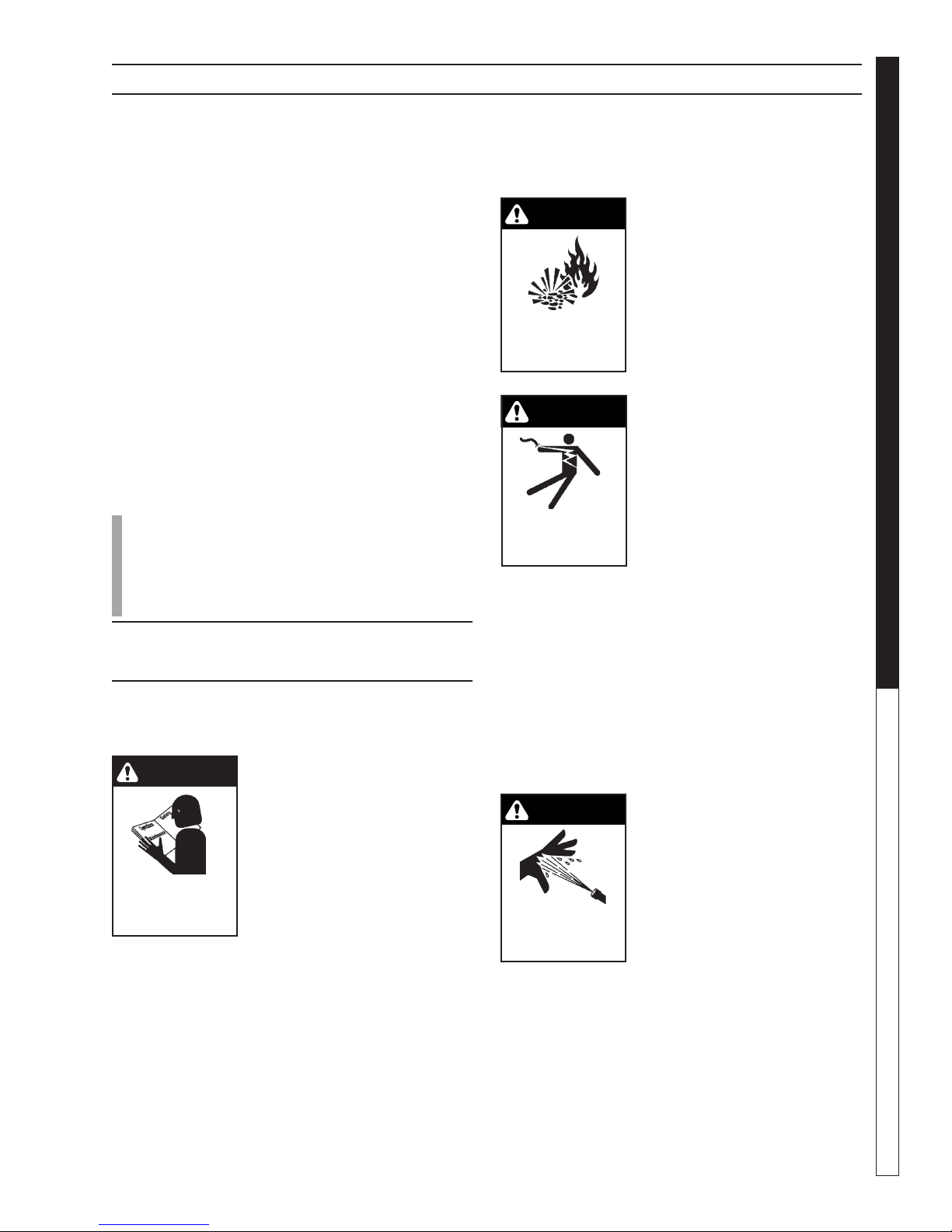
CAUTION: To reduce the risk of
injury, read operating instructions carefully before using.
1. Read the owner's manual
thoroughly. Failure to follow
in str uctions could cause
malfunction of the machine
and result in death, serious
bodily injury and/or property
damage.
3. Know how to stop the machine and bleed pressures quickly. Be thoroughly familiar with the
controls.
4. Stay alert. Watch what you are doing.
WARNING: Flammable liquids
can create fumes which can
ignite causing property damage or severe injury.
5. Risk of explosion - Do not
spray flammable liquids or
RISK OF EXPLOSION:
DO NOT SPRAY FLAM
MABLE
LIQUIDS.
-
operate in an explosive location. Operate only where
open flame or torch is permitted.
WARNING: Keep water spray
away from electrical wiring or
fatal electric shock may result.
Read warning tag on electrical
cord.
6. To protect the operator from
KEEP WATER SPRAY
AWAY FROM
ELECTRICAL WIRING.
electrical shock, the machine
must be electrically grounded. It is the responsibility
of the owner to connect this
machine to a UL grounded receptacle of proper
voltage and amperage ratings. Do not spray water
on or near electrical components. Do not touch
machine with wet hands or while standing in water.
Always disconnect power before servicing.
WARNING: Spray gun kicks back. Hold with both
hands.
7. Grip cleaning wand securely with both hands before starting the cleaner. Failure to do this could
result in injury from a whipping wand.
WARNING: Equipment can produce a high pressure stream of
fluid that can pierce skin and its
underlying tissues, leading to
serious injury and possible
amputation.
RISK OF INJECTION
OR SEVERE INJURY
TO PERSONS. KEEP
CLEAR OF NOZZLE.
8. High pressure developed by
these machines can cause
personal injury or equipment
damage. Use caution when operating. Do not
direct discharge stream at anyone or at any part
of the body, or severe injury or death will result.
This machine is to be used only by qualified operators.
OPERATOR’S MANUAL
5
SHARK HNG • 97-610 • REV. 3/06
WARNING
WARNING
WARNING
WARNING
WARNING
INTRODUCTION & SAFETY INFORMATION
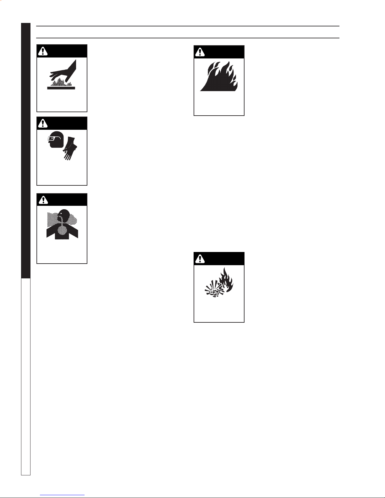
CAUTION: Hot discharge fluid.
Do not touch or direct discharge stream at persons.
9. Never make adjustments on
machine while in operation.
EXTREMELY HOT:
USE CAUTION WHEN
OPENING LID.
PRESSURE WASHER
WARNING: High pressure can
cause paint chips or other particles to become airborne and
fly at high speeds.
10. Eye safety devices and foot
PROTECTIVE EYE-
WEAR AND CLOTHING
OPERATOR’S MANUAL
ASPHYXIATION.
USE ONLY IN A WELL
VENTILATED AREA.
MUST
BE WORN.
RISK OF
for extensive periods of time as this may cause
damage to the pump.
13. Protect from freezing.
14. Be certain all quick coupler fittings are secured
before using pressure washer.
1 5. Do not allow acids, caustic, or abrasive fluids to
pass through the pump.
16. Inlet water must be cold and clean fresh water.
17. To reduce the risk of injury, close supervision is
necessary when a machine is used near children.
Do not allow children to operate the pressure
washer. This machine must be attended dur-
ing operation.
1 8. The best insurance against an accident is pre-
caution and knowledge of the machine.
19. Do not operate this product when fatigued or under
the influence of alcohol or drugs. Keep operating
area clear of all persons.
20. Do not replace LP tank while machine is running.
Serious injury could result.
protection must be worn
when using this equipment.
WARNING: Risk of asphyxiation. Use this product only in
a well ventilated area.
11. When the machine is working, do not cover or place in
a closed space where ventilation is insufficient.
12. Machines with spray guns
should not be operated with
the trigger in the off position
WARNING: Use only vapor propane fuel.
21. This equipment is designed
to run on vapor fuel. Do not
use liquid fuel. Have a qualified serviceman install and
RISK OF FIRE.
DO NOT USE WITH
FLAMMABLE LIQUIDS.
service your equipment.
22. Never expose a spark or
flame where unburned gas
may be present.
23. Never attempt to light pilot unless pilot manual
valve has been shut off for 5 minutes.
24. A conversion kit, as supplied by the manufacturer,
shall be used to convert natural gas to propane.
25. L.P. gases are heavier than air and will spill out on
the floor. Therefore always provide adequate space
and ventilation around these machines. Install
machine 18" above the floor.
26. Manufacturer will not be liable for any changes
made to our standard machines, or any components not purchased from the manufacturer.
27. Do not overreach or stand on unstable support.
Keep good footing and balance at all times.
28. Follow maintenance instructions specified in the
manual.
29. When making repairs disconnect from electrical source
and sh u t off gas val ve .
30. Turn burner off, open spray
gun and cool to 100° F before
turning machine off.
RISK OF EXPLOSION:
IF GAS SMELL
PRESENT TURN
OFF SUPPLY
31. Extinguish any open flame
and test all joints with a
soap solution. If odor persists, call your gas supplier
immediately.
32. Not suitable for connection to Type B gas vent if
the stack temperature exceeds 243° C (470° F).
33. A draft diverter shall be installed if this machine is
going to be permanently installed and vented to
the outside of the building.
6
SHARK HNG • 97-610 • REV. 3/06
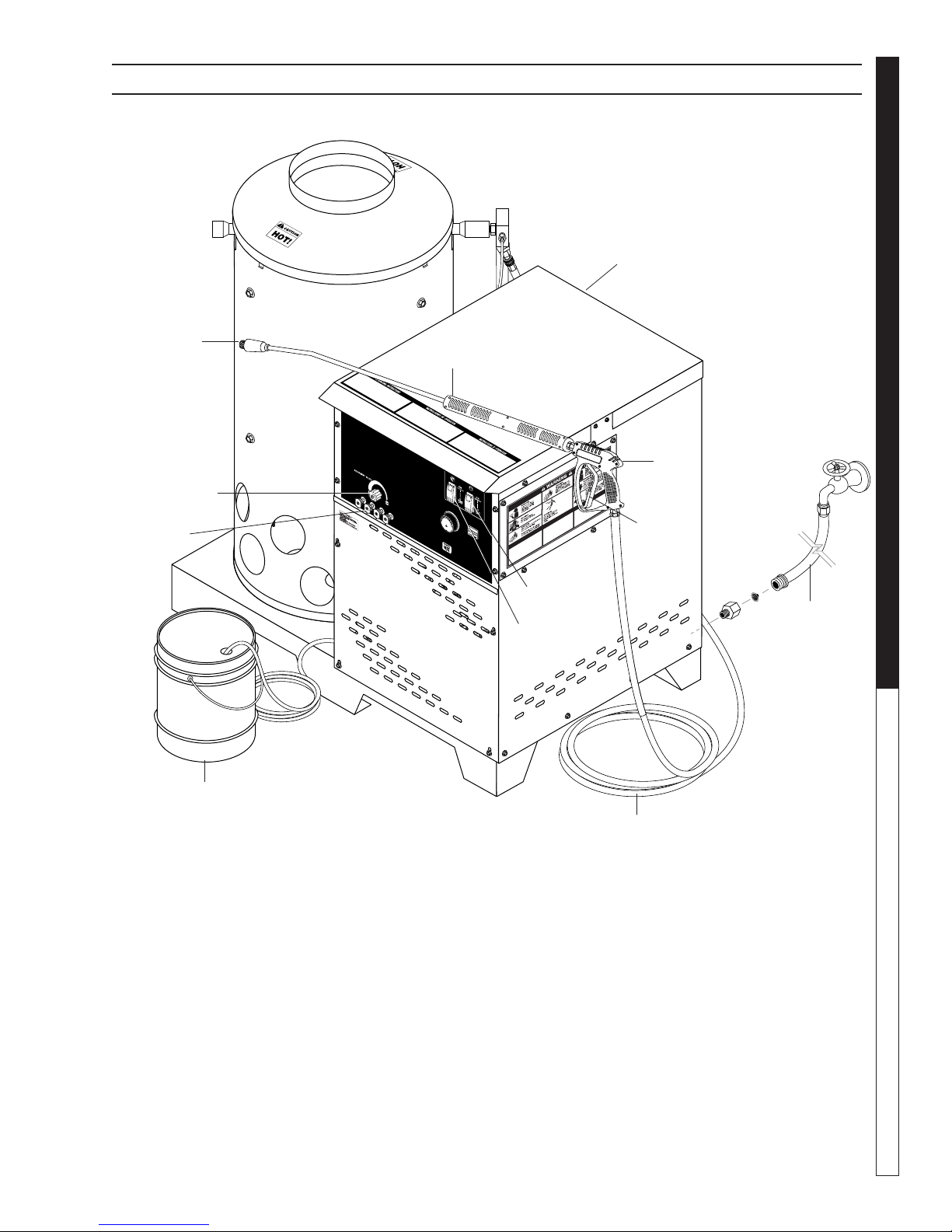
COMPONENT IDENTIFICATION
Main Gas
Supply Inlet
1/2 psig
PRESSURE WASHER
OPERATOR’S MANUAL
Wand Quick
Coupler
Detergent
Valve
Pressure
Nozzles
Spray
Wand
Burner
Switch
Pump
Switch
Spray
Gun
Trigger
Water Supply
Hose
(not included)
Detergent Bucket
(optional)
Pump — Develops high pressure.
Pump/Burner Switch— Controls operation on ma-
chine.
Spray Gun — Controls the application of water and
detergent onto cleaning surface with trigger device.
Includes safety latch.
Detergent Valve — Allows you to siphon and mix
detergents.
Wand — Must be connected to the spray gun.
High Pressure Hose — Connect one end to water
pump discharge nipple and the other end to spray
gun.
Wand Quick Coupler — Pulling the brass collar back
allows the insertion of pressure nozzle.
Note: If trigger on spray gun is released for more
than 2 minutes, water will leak from valve. Warm
water will discharge from pump protector onto
floor. This system prevents internal pump damage.
SHARK HNG • 97-610 • REV. 3/06
High Pressure
Hose
7
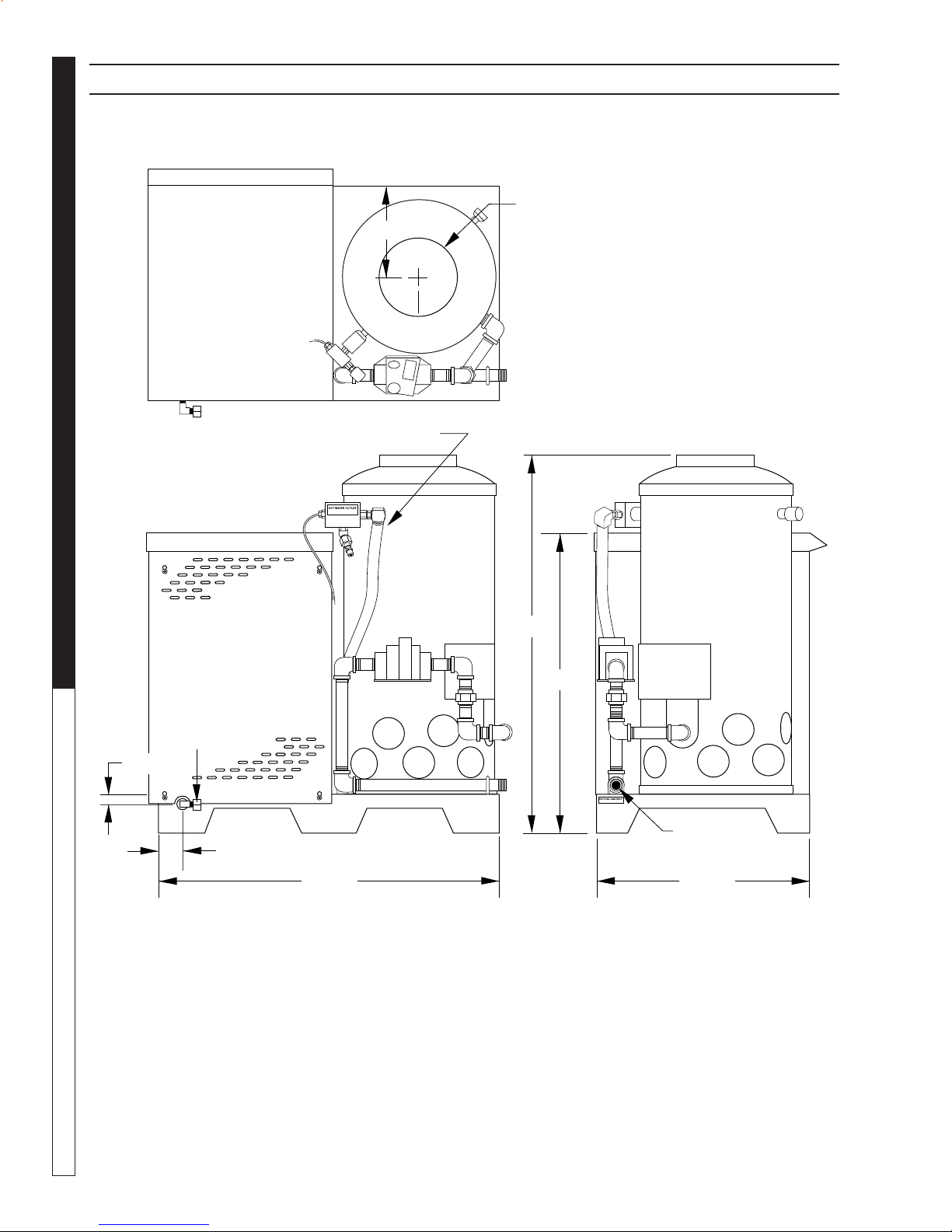
INSTALLATION
9.57" I.D.
11-3/4"
PRESSURE WASHER
OPERATOR’S MANUAL
Fresh Water
In 1.0" GHF
1-1/4"
3.0"
High Pressure Out
44-1/4"
49-0"
38-3/8"
Gas In
1-1/2" NPT-M
27-1/2"
8
SHARK HNG • 97-610 • REV. 3/06
INSTALLATION
PRESSURE WASHER
Place machine in a convenient location providing ample support, drainage and room for maintenance (see
page 8).
Location:
The location should protect the machine from damaging environmental conditions, such as wind, rain
and freezing.
1. The machine should be run on a level surface
where it is not readily influenced by outside sources such as strong winds, freezing temperatures,
rain, etc. The machine should be located considering accessibility for the replacing of components
and the refilling of detergents, adjustments and
maintenance. Normal precautions should be taken
by the operator of the machine to prevent excess
moisture from reaching the power unit or electrical
controls.
2. It is recommended that a partition be made between the wash area and the machine to prevent
direct spray from the spray gun from coming
in contact with the machine. Excess moisture
reaching the power unit or electrical controls will
reduce the machine’s life and may cause electrical
shorts.
3. During installation of the machine, beware of
poorly ventilated locations or areas where exhaust
fans may cause an insufficient supply of oxygen.
Sufficient combustion can only be obtained when
there is a sufficient supply of oxygen available for
the amount of fuel being burned. If it is necessary
to install a machine in a poorly ventilated area, outside fresh air may have to be piped to the burner
and a fan installed to bring the air into the area.
4. Do not locate near any combustible material. Keep
all flammable material at least 20 feet away.
Allow enough space for servicing the machine.
Local code will require certain distances from floor
and walls. (Two feet away should be adequate).
WARNING: Avoid small areas or near exhaust
fans.
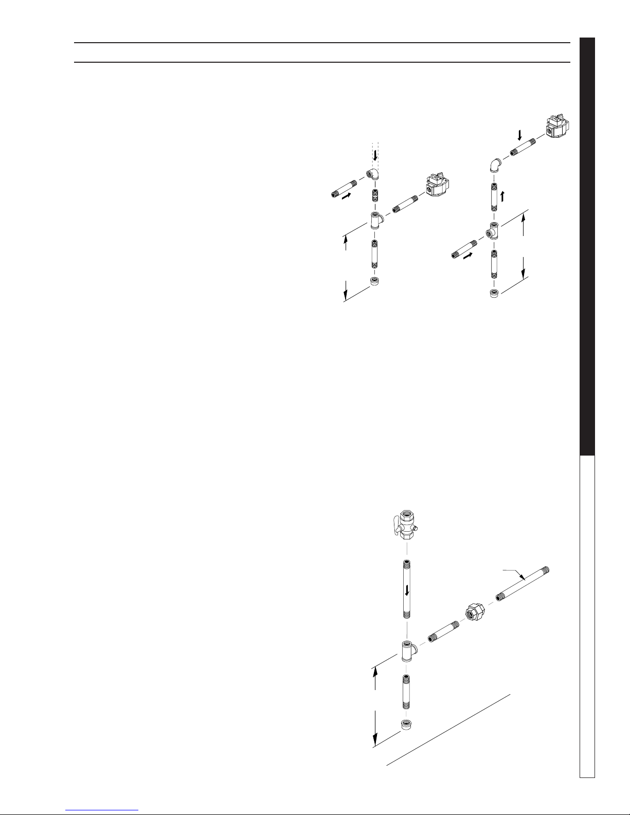
Gas Piping:
Figure 1: DRIP LEG
Drop
Gas
Valve
3"
(7.62 mm)
Minimum
Sediment trap (drip leg) must be
installed in the supply line.
Install a union in the gas line adjacent to and upstream
from the control manifold and downstream from the
manual main shut-off valve. A 1/8" NPT plugged
tapping accessible for test gauge connection shall
be installed immediately upstream of the gas supply
connection for the purpose of determining the gas
supply pressure to the burner, and to prevent damage to gas valve.
If a manual gas shut off valve is not in the gas supply
line within six feet of the machine and in an accessible
location, one shall be installed.
Figure 2: UNION LOCATION
Manual
Shut-Off Valve
1/8" NPT Plugged
Pressure Gauge
Flow
Port Location
1/4" Test Port
(6" - 14 W.C.
or 1/2" PSIG)
Gas
Valve
3" (7.62 mm)
Minimum
To
Gas Valve
OPERATOR’S MANUAL
Gas Codes:
Confer with local gas company and with proper municipal officials regarding any specific code or regulations governing the installation. The installation must
conform to local codes.
Electrical:
The machine, when installed, must be electrically
grounded in accordance to local codes. Check for
proper power supply using a volt meter; check the
serial plate for the correct requirements.
3" (7.62 mm)
Minimum
SHARK HNG • 97-610 • REV. 3/06
Tee
Union
Control Manifold
Pipe
Cap
Floor Level
9

INSTALLATION
PROPANE
Length of Pipe
(ft.)
Iron Pipe Size
1/2" 3/4"
10 3339 6982
20 2295 4799
30 1843 3854
40 1577 3298
50 1398 2923
60 1267 2649
70 1165 2437
80 1084 2267
90 1017 2127
100 961 2009
150 772 1613
200 660 1381
250 585 1224
300 530 1109
350 488 1020
400 454 949
450 426 890
500 402 841
PROPANE
Length of
pipe (ft.)
Iron Pipe Size
1/2" 3/4" 1"
10 291 608 1146
20 200 418 788
30 161 336 632
40 137 287 541
50 122 255 480
60 110 231 435
70 102 212 400
80 94 198 372
90 87 185 349
100 84 175 330
NATURAL GAS
Length
of Pipe
(ft.)
Iron Pipe Size
3/4" 1"
1-1/4-"1-1/2-
"
2"
10 360 680 1400 2100 3950
20 250 465 950 1460 2750
30 200 375 770 1180 2200
40 170 320 660 990 1900
50 151 285 580 900 1680
60 138 260 530 810 1520
70 125 240 490 750 1400
80 118 220 460 690 1300
90 110 205 430 650 1220
100 103 195 400 620 1150
150 84 160 325 500 950
200 72 135 280 430 800
The following pipe and stack sizes are just recommendations. Always consult a local plumber and venting contractor for local codes and regulations during
installation.
The following tables are maximum capacity of final
stage pipe in thousands of Btu/hr of commercial
propane
From first stage regulator (at tank) to second stage
PRESSURE WASHER
regulator
The chart below is based on incoming gas pressure
of 10 PSI and a pressure drop of 1 PSI. Numbers are
for straight schedule 40 pipe; fittings further reduce
capacity.
OPERATOR’S MANUAL
From second stage regulator to machine.
The following chart is based on incoming gas pressure
of 11 w.c.i. and a pressure drop of .5 w.c.i. Numbers
are for straight schedule 40 pipe; fittings further reduce
capacity.
10
The chart below is based on gas pressure in the range
0-.5 PSI, specific gravity of .6, and pressure loss of
.5 w.c.i. Numbers are for straight schedule 40 pipe;
fittings further reduce capacity.
SHARK HNG • 97-610 • REV. 3/06
INSTALLATION
PRESSURE WASHER
Venting:
This machine is to be used indoors and requires
ventilation.
When venting the machine, if the machine is to be in
an enclosed area with a vent pipe, be sure it is the
same size as the stack on the machine. Poor draft will
cause the machine to soot and not operate efficiently.
When placing the machine for installation, position the
vent pipe to be as straight as possible and to protrude
through the roof of the building at a proper location and
at sufficient height to eliminate down-draft. Venting of a
gas fired machine shall be installed with a down-draft
diverter located about 3 ft. above machine.
Input - BTU Per Hour Draft Hood & Flue Pipe
Size
250,000 - 320,000 8 inch
320,000 - 410,000 9 inch
410,000 - 600,000 10 inch
600,000 - 750,000 12 inch
NOTE: If the vent pipe exceeds 10 ft. in length, or
contains more than two elbows, use next size larger
pipe and draft diverter or the burner will not ignite. No
movable vent pipe damper should be used on any
installation.
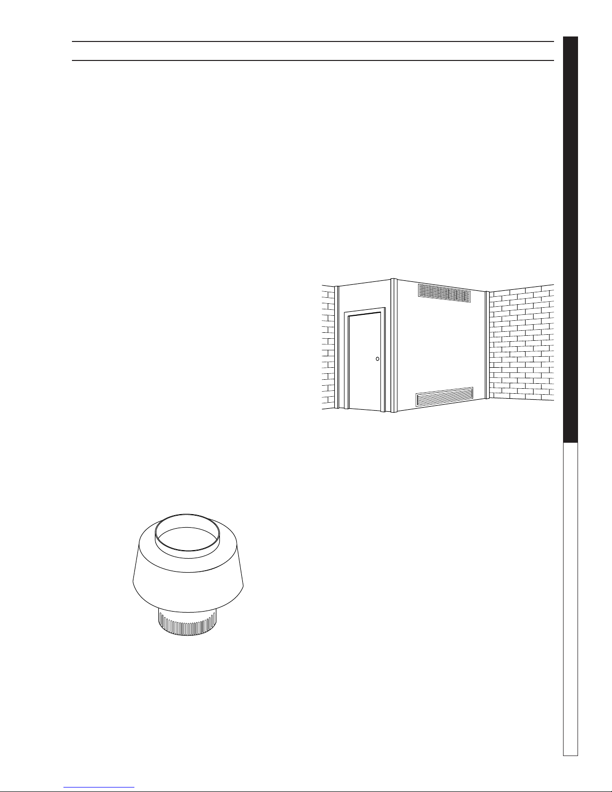
ceiling, each to be sized on the basis of one square
inch or more of free area for each 1,000 BTU input
per hour (see Figure 4).
When a room is of unusually tight construction and
has a ventilating fan, which may be used for exhausting air outdoors -or has a vented exhaust — it
is recommended that combustion air be supplied to
the enclosed room through intakes extending to the
outside of the building and terminating in down-turned
fittings. These should be suitably arranged to prevent
obstruction from snow or rain, and include a protecting
screen not smaller than 1/4 inch mesh.
Figure 4
Ventilating Air Opening.
1 square inch for each
1000 BTU per hour input.
OPERATOR’S MANUAL
Draft Diverter:
Install the draft diverter above the heating coil. The
diverter enhances the draft through the burner by severing the chimney effect created in sections of vent
pipe positioned below. It also helps prevent freezing
of the coil due to wind chill factors.
Figure 3
Optional
When in a tightly closed room without ventilation openings to the outdoors or other rooms, provisions shall be
made for supplying air for combustion through special
openings, one near the floor and the other near the
Illustration showing air openings necessary
to supply air for combustion when installed
in an enclosed room.
Water Source:
The water source for the machine should be supplied
by a 5/8" I.D. garden hose with a city water pressure of
not less than 30 PSI. If the water supply is inadequate,
or if the garden hose is kinked, the machine will run
very rough and the burner will not fire.
Water Connection:
Connect the high pressure hose by pulling the coupler
collar back and then inserting it onto the discharge
nipple. Secure it by pushing the collar forward.
Attach the wand into the spray gun using teflon tape
on the pipe threads to avoid leaks.
Inspection and Testing Gas Piping:
The building structure should not be weakened by
installing the gas piping. The piping should not be
supported by other piping, but should be firmly supported with gas hooks, straps, bands or hangers. Butt
or lap welded pipe should not be run through or in an
air duct or clothes chute.
11
SHARK HNG • 97-610 • REV. 3/06

INSTALLATION
FOR YOUR SAFETY READ BEFORE LIGHTING
WARNING
If you do not follow these instructions exactly, a fire or
explosion may result, causing property damage, personal
injury or loss of life.
A. This appliance has a pilot which must be lighted by
hand.
When lighting the pilot, follow these instructions exactly.
B. BEFORE LIGHTING smell all around the appliance area
for gas. Be sure to smell next to the floor because some
gas is heavier than air and will settle on the floor.
FOR YOUR SAFETY
"WHAT TO DO IF YOU SMELL GAS"
� Do not try to light any appliance.
� Do not touch any electrical switch, do not use any phone
in your building.
� Immediately call your gas supplier from a neighbor's
phone. Follow the gas supplier's instructions.
� If you cannot reach your supplier, call the fire
department.
C. Use only your hand to push in or turn the gas control
knob. Never use tools. If the knob will not push in or turn
by hand, don't try to repair it; call a qualified service
technician. Forced or attempted repair may result in a
fire
or explosion.
D. Do not use this appliance if any part has been under
water. Immediately call a qualified service technician to
inspect the appliance and to replace any part of the
control system and any gas control which has been
under water.
YES NO
Has gas supply been inspected by an
authorized contractor to meet local
codes?
Is machine protected from downdraft and
excessive wind?
Is machine shielded from moisture or
water spray?
Is the voltage correct and are the circuit
breaker and supply cord adequate
according to specifications and serial
plate notation?
Is the machine electrically grounded?
Is there ample water supply?
Have all flammable liquids or gases been
removed from installation location?
Is there adequate gas supply for the BTU
rating of the burner?
Is incoming gas supply pressure between
6 - 14 water column inches or 1/2 PSIG?
Has the proper gas regulator been
installed for pressure and volume?
Is the machine properly vented to allow
adequate air flow?
Are the propane tanks large enough,
according to rating to prevent freezing
(vapor propane machines only)?
Have gas lines been checked for gas
leaks?
Have gas lines been checked with local
codes?
Have all operators using this machine
been instructed properly & have they
read the manual?
Has the machine been installed
according to operator's manual
instructions?
Before turning gas under pressure into piping, all openings from which gas can escape should be closed.
Immediately after turning on gas, the system should
be checked for leaks. This can be done by watching the
1/2 cubic foot test dial for 5 minutes for any movement
or by soaping each pipe connection and watching for
bubbles. If a leak is found, make the necessary repairs
and repeat the above test.
Defective pipes or fittings should be replaced and not
PRESSURE WASHER
repaired. Never use a flame or fire in any form to locate
gas leaks — use a soap solution.
After the piping and meter have been checked completely, purge the system of air. DO NOT bleed the air
inside an enclosed room.
During pressure testing of the system at test pressures in excess of 1/2 PSIG, the appliance and its
individual shut-off valve must be disconnected from
OPERATOR’S MANUAL
the gas supply piping system or damage to the gas
valve will occur.
12
Gas Pressure:
The ideal incoming gas pressure is 11 water column
inches or w.c.i. (min. 6 wc”, max. 14 wc” or 1/2 PSIG).
The correct operating manifold pressure for natural gas
is 3.5 wc” The operating manifold pressure for propane
gas is 10 wc” By adjusting the gas valve pressure
regulator between 3 and 4 wc” a side range can be
achieved for natural gas. Propane is 6-10 wc”.
If the desired input rating cannot be obtained within the
above manifold pressure adjusting range, then the next
size larger or smaller burner orifice should be used.
CHECK LIST BEFORE
STARTING:
CAUTION! If “NO” is checked on any of the following sixteen questions, do not operate this
machine.
SHARK HNG • 97-610 • REV. 3/06
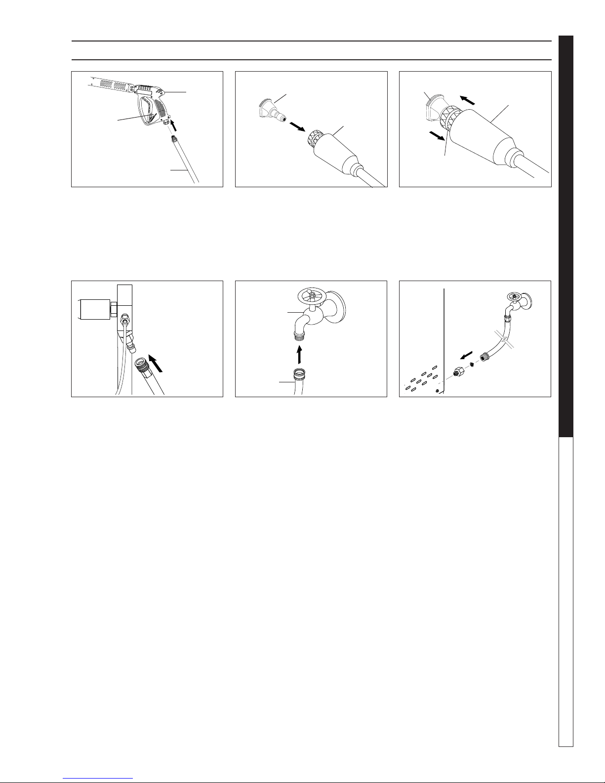
ASSEMBLY INSTRUCTIONS
PRESSURE WASHER
Spray
Gun
Safety
Latch
High Pressure
Hose
STEP 1: Attach the high pressure
hose to the spray gun using teflon
tape on hose threads.
Pressure
Nozzle
Wand
Coupler
STEP 2: Pull the spring-loaded col-
lar of the wand coupler back to insert your choice of pressure nozzle.
CAUTION: Never replace nozzles
without engaging the safety latch
on the spray gun trigger.
Cold Water
Source
Pressure
Nozzle
Wand
Collar
Wand
Coupler
STEP 3: Release the coupler collar
and push the nozzle until the collar
clicks. Pull the nozzle to make sure
it is seated properly.
Garden
Hose
OPERATOR’S MANUAL
STEP 4: Connect the high pressure
hose to the pump discharge fitting.
Push coupler collar forward until
secure.
Garden
Hose
STEP 5: Connect garden hose to
the cold water source.
Water Inlet
STEP 6: Check inlet filters, re-
move debris, then connect the
garden hose to pump water inlet.
CAUTION: Do not run the pump
without water or pump damage
will result.
13
SHARK HNG • 97-610 • REV. 3/06
Cold Water
Source
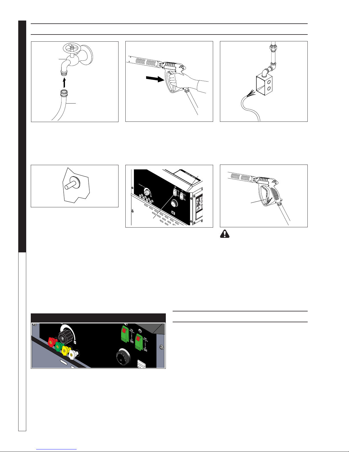
OPERATING INSTRUCTIONS
PRESSURE WASHER
Garden
Hose
STEP 1: Review installation instruc-
tions prior to connecting garden
hose to the cold water source and
turn water on completely. Never use
hot water.
OPERATOR’S MANUAL
STEP 4: Depress control knob and
hold it in. After 5 seconds, depress
the red ignitor until you hear a loud
click. Repeat 3 or 4 times if necessary until pilot is lit. If pilot does
not remain lit, repeat operation,
allowing a longer period of time
before releasing the knob. After the
pilot lights, continue to hold the control knob down for 1 minute. Note:
Sufficient time must be allowed for
a proper size pilot flame to heat the
thermocouple and hold the safety
magnet in a locked-up position.
STEP 2: Trigger the spray gun to
eliminate trapped air then wait for a
steady flow of water to emerge from
the spray nozzle.
Burner
Switch
Pump
Switch
STEP 5: Turn gas cock dial (located
on rear of machine) to “PILOT” position. Release dial and turn to full
ON. Push pump switch ON, or turn
to pump position and pull the trigger
on the spray gun allowing cold water
to flow. To activate the gas control
valve for hot water, push the burner
switch to the ON position and pull
the trigger on the spray gun.
STEP 3: Have an electrician connect power supply into junction box
according to information shown on
the serial plate before turning gas
valve dial to “PILOT” position.
Safety
Latch
WARNING! Never replace nozzles without engaging the safety
latch on the spray gun trigger.
NOZZLES
The five color-coded quick connect nozzles provide a
wide array of spray widths from 0° to 45° and are easily
accessible when placed in the convenient rubber nozzle
holder, which is provided on the front of the machine.
NOTE: For a more gentle rinse, select the white 40°
or green 25° nozzle. To scour the surface, select the
yellow 15° or red 0° nozzle. To apply detergent select
the black nozzle.
14
AUTO IGNITION OPTION
If your machine has Auto Ignition option,
follow these steps.
1. Have electrician connect power supply into junction
box according to information shown on serial plate
and open main gas supply.
2. Push pump switch to “ON” position, pull trigger on
spray gun.
3. After water and pressure is exiting pressure nozzle
push burner switch “ON”. Note: Thermostat should
be set at 200°.
4. The pilot will ignite first then you will notice a flash of
light indicating complete ignition. Note: You should
hear a clicking sound before the pilot ignites.
SHARK HNG • 97-610 • REV. 3/06
 Loading...