

Shark HNG-4020, HNG-3530, HNG-5030, HNG-3010 Operator's Manual

HNG
OPERATOR’S MANUAL
■ HNG-4020 ■ HNG-3530 ■ HNG-5030
L
D
I
S
E
®
T
SHARK PRESSURE WASHERS ■ 4275 N.W. Pacific Rim Blvd. ■ Camas, WA 98607 ■ USA
For technical assistance or the Shark Dealer nearest you, call 1-800-771-1881.

2
CONTENTS
Introduction................................................................................................................................... 3
Important Safety Information .....................................................................................................3-4
Installation ................................................................................................................................. 4-8
Installation Guide .......................................................................................................................... 5
Start-up ..................................................................................................................................... 8-9
Check List Before Starting .......................................................................................................... 10
Component Identification ............................................................................................................ 11
Operating Instructions ................................................................................................................ 12
Preventatative Maintenance........................................................................................................ 12
General Washing Techniques ................................................................................................12-13
Maintenance & Service............................................................................................................... 13
Heating Coils ......................................................................................................................... 13-14
Propane Gas .............................................................................................................................. 14
Burner Features.......................................................................................................................... 15
Burner Troubleshooting .......................................................................................................... 15-16
Hose & Spray Gun Assembly ..................................................................................................... 17
Exploded View, Left Side ............................................................................................................ 18
Exploded View, Right Side .......................................................................................................... 19
Exploded View, Parts List ...................................................................................................... 20-21
Burner Assembly, Exploded View ............................................................................................... 22
Burner Assembly, Exploded View, Parts List ............................................................................... 23
Control Panel .............................................................................................................................. 24
Control Panel, Parts List ............................................................................................................. 25
Float Tank Assembly ................................................................................................................... 26
Electrical Box, Standard ............................................................................................................. 27
Electrical Box, Time Delay ..................................................................................................... 28-29
Electrical Box, Auto Start ....................................................................................................... 30-31
Troubleshooting ................................................................................................................... 332-33
Basic Facts ................................................................................................................................. 34
Pressure Equivalents.................................................................................................................. 34
Preventative Maintenance Schedule ........................................................................................... 35
Oil Change Record ..................................................................................................................... 35
Warranty
Model Number ______________________________
Serial Number ______________________________
Date of Purchase ____________________________
The model and serial numbers will be found on a decal attached to
the pressure washer. You should record both serial number and
date of purchase and keep in a safe place for future reference.
Shark HNG Manual • Form #97-610 • Revised 2/03a
HNG SERIES PRESSURE WASHER
WARNING
WARNING
WARNING
OPERATOR’S MANUAL
3
INTRODUCTION
Thank you for purchasing a Shark Pressure Washer.
This manual covers the operation and maintenance of
the HNG-402001A, 402007A, 353001A, 353007A,
503001B, 503007B, 503001C, and 503007C washers.
All information in this manual is based on the latest product information available at the time of printing.
Shark, Inc. reserves the right to make changes at any
time without incurring any obligation.
The HNG Series was designed for
maximum use of 4 hours per day,
5 days per week.
Owner/User Responsibility:
The owner and/or user must have an understanding of
the manufacturer’s operating instructions and warnings
before using this Shark pressure washer. Warning information should be emphasized and understood. If the
operator is not fluent in English, the manufacturer’s instructions and warnings shall be read to and discussed
with the operator in the operator’s native language by
the purchaser/owner, making sure that the operator comprehends its contents.
Owner and/or user must study and maintain for future
reference the manufacturers’ instructions
This manual should be considered a permanent
part of the machine and should remain with it if
machine is resold.
When ordering parts, please specify model and
serial number.
IMPORTANT SAFETY
INFORMATION
WARNING: When using this machine basic
precautions should always be followed, including the
following:
CAUTION
READ OPERATOR’S
MANUAL
THOROUGHLY
PRIOR TO USE.
CAUTION: To reduce the risk of
injury, read operating instructions
carefully before using.
1. Read the owner's manual
thoroughly. Failure to follow instructions could cause malfunction of the machine and result
in death, serious bodily injury
and/or property damage.
2. All installations must comply with local codes. Contact your electrician, plumber, utility company or the
selling distributor for specific details.
3. Know how to stop the machine and bleed pressures
quickly. Be thoroughly familiar with the controls.
4. Stay alert. Watch what you are doing.
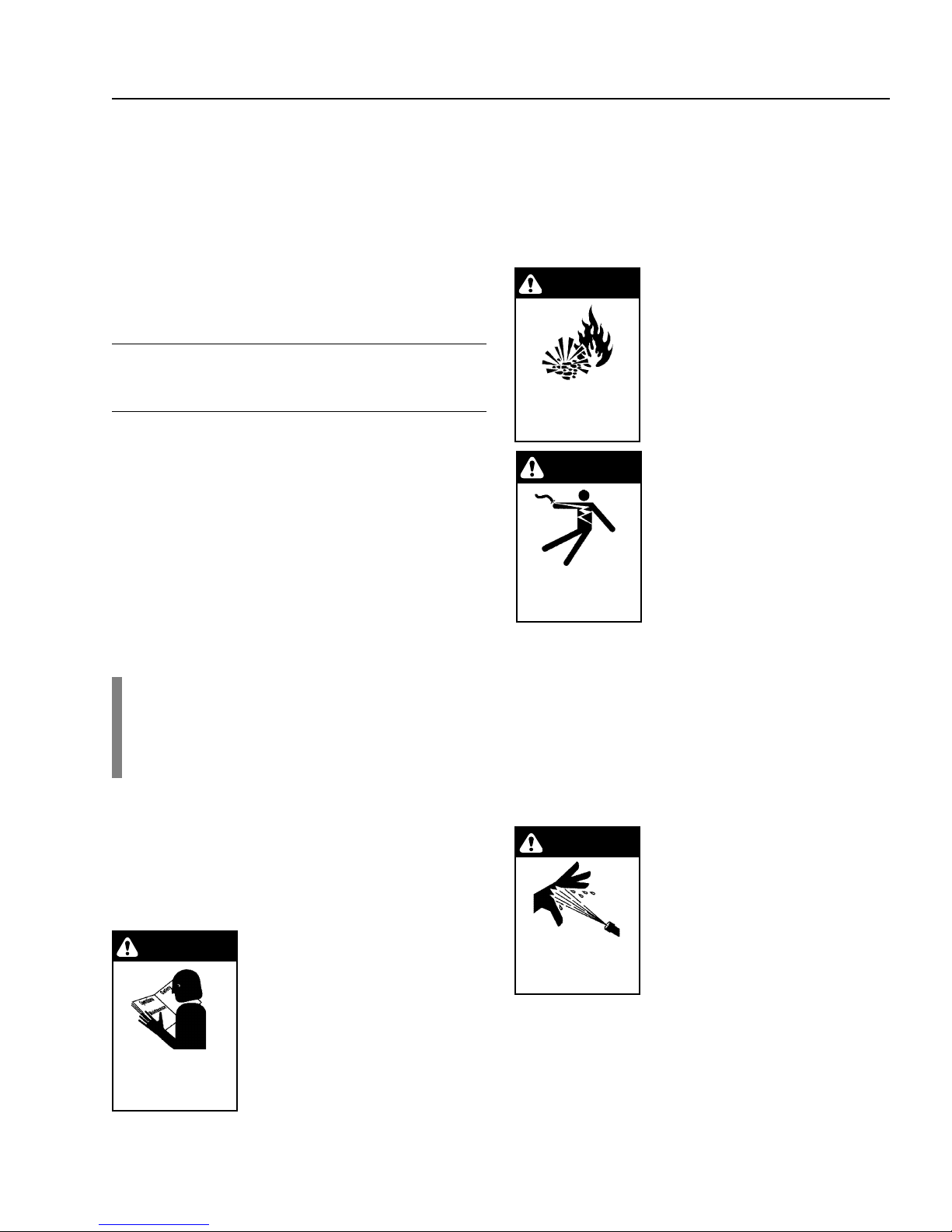
WARNING: Flammable liquids
can create fumes which can ignite
causing property damage or
severe injury.
5. Risk of explosion - Do not spray
flammable liquids or operate in
RISK OF EXPLOSION:
DO NOT SPRAY
FLAMMABLE
LIQUIDS.
an explosive location. Operate
only where open flame or torch
is permitted.
WARNING: Keep water spray
away from electrical wiring or fatal electric shock may result.
Read warning tag on electrical
cord.
6. To protect the operator from
KEEP WATER SPRAY
AWAY F R OM
ELECTRICAL WIRING.
electrical shock, the machine
must be electrically grounded.
It is the responsibility of the
owner to connect this machine
to a UL grounded receptacle of proper voltage and
amperage ratings. Do not spray water on or near
electrical components. Do not touch machine with
wet hands or while standing in water. Always disconnect power before servicing.
WARNING: Spray gun kicks back. Hold with both hands.
7. Grip cleaning wand securely with both hands before
starting the cleaner. Failure to do this could result in
injury from a whipping wand.
WARNING: Equipment can produce a high pressure stream of
fluid that can pierce skin and its
underlying tissues, leading to
serious injury and possible
amputation.
RISK OF INJECTION
OR SEVERE INJURY
TO PERSONS. KEEP
CLEAR OF NOZZLE.
8. High pressure developed by
these machines can cause
personal injury or equipment
damage. Use caution when operating. Do not direct
discharge stream at anyone or at any part of the
body, or severe injury or death will result. This machine is to be used only by qualified operators.
Shark HNG • Rev. 2/03a
4
HNG SERIES PRESSURE WASHER
OPERATOR’S MANUAL
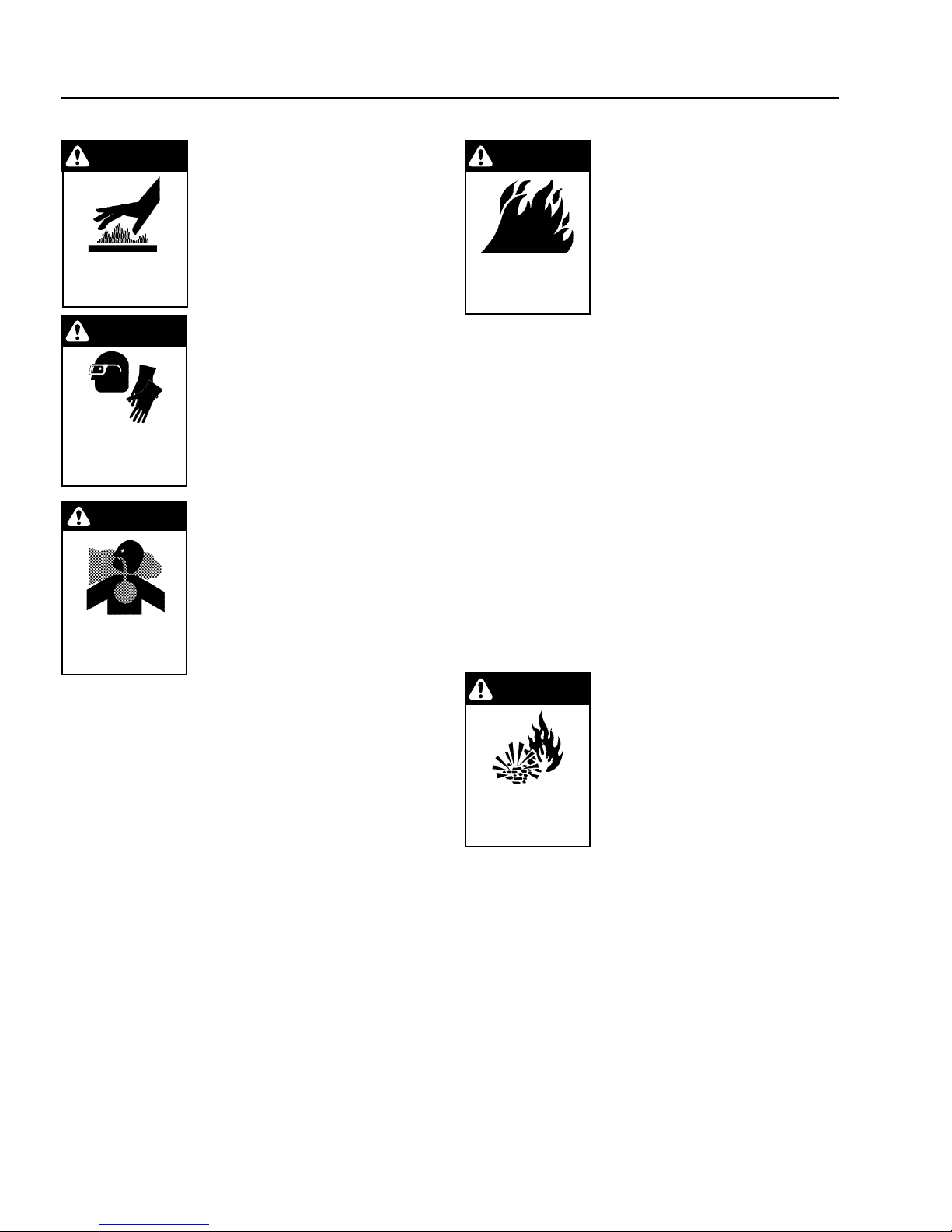
WARNING
CAUTION: Hot discharge fluid. Do
not touch or direct discharge
stream at persons.
9. Never make adjustments on
machine while in operation.
EXTREMELY HOT:
USE CAUTION WHEN
OPENING LID.
WARNING
WARNING: High pressure can
cause paint chips or other particles to become airborne and fly
at high speeds.
10. Eye safety devices and foot pro-
PROTECTIVE
EYEWEAR AND
CLOTHING MUST
BE WORN.
WARNING
tection must be worn when
using this equipment.
WARNING: Risk of asphyxiation.
Use this product only in a well
ventilated area.
11. When the machine is working,
do not cover or place in a closed
space where ventilation is insuf-
RISK OF
ASPHYXIATION.
USE ONLY IN A WELL
VENTILATED AREA.
ficient.
12. Machines with spray guns
should not be operated with the
trigger in the off position for extensive periods of time
as this may cause damage to the pump.
13. Protect from freezing.
14. Be certain all quick coupler fittings are secured
before using pressure washer.
15. Do not allow acids, caustic, or abrasive fluids to pass
through the pump.
16. Inlet water must be cold and clean fresh water.
17. To reduce the risk of injury, close supervision is necessary when a machine is used near children. Do
not allow children to operate the pressure washer.
This machine must be attended during operation.
18. The best insurance against an accident is precaution and knowledge of the machine.
19. Do not operate this product when fatigued or under
the influence of alcohol or drugs. Keep operating area
clear of all persons.
20. Do not replace LP tank while machine is running.
Serious injury could result.
Shark HNG • Rev. 2/03a
WARNING
WARNING: Use only vapor fuel.
21. This equipment is designed to
run on vapor fuel. Do not use
liquid fuel. Have a qualified serviceman install and service
your equipment.
RISK OF FIRE.
DO NOT USE WITH
FLAMMABLE LIQUIDS.
22. Never expose a spark or flame
where unburned gas may be
present.
23. Never attempt to light pilot unless pilot manual valve
has been shut off for 5 minutes.
24. A conversion kit, as supplied by the manufacturer,
shall be used to convert natural gas to propane.
25. L.P. gases are heavier than air and will spill out on
the floor. Therefore always provide adequate space
and ventilation around these machines. Install
machine 18" above the floor.
26. Shark will not be liable for any changes made to our
standard machines, or any components not purchased from Shark.
27. Do not overreach or stand on unstable support. Keep
good footing and balance at all times.
28. Follow maintenance instructions specified in the
manual.
29. When making repairs disconnect from electrical
source and shut off gas valve.
WARNING
30. Turn burner off and cool to
100° F before turning machine
off.
31. Extinguish any open flame and
test all joints with a soap solution. If odor persists, call your
RISK OF EXPLOSION:
IF GAS SMELL
PRESENT TURN
OFF SUPPLY
gas supplier immediately.
32. Not suitable for connection
to Type B gas vent if the stack
temperature exceeds 243° C
(470° F).
33. A draft hood shall be installed if this machine is
going to be permanently installed and vented to the
outside of the building.
INSTALLATION
Place machine in a convenient location providing ample
support, drainage and room for maintenance (see page 5).
Location:
The location should protect the machine from damaging
environmental conditions, such as wind, rain and freezing.
1. The machine should be run on a level surface where
it is not readily influenced by outside sources such
as strong winds, freezing temperatures, rain, etc. The
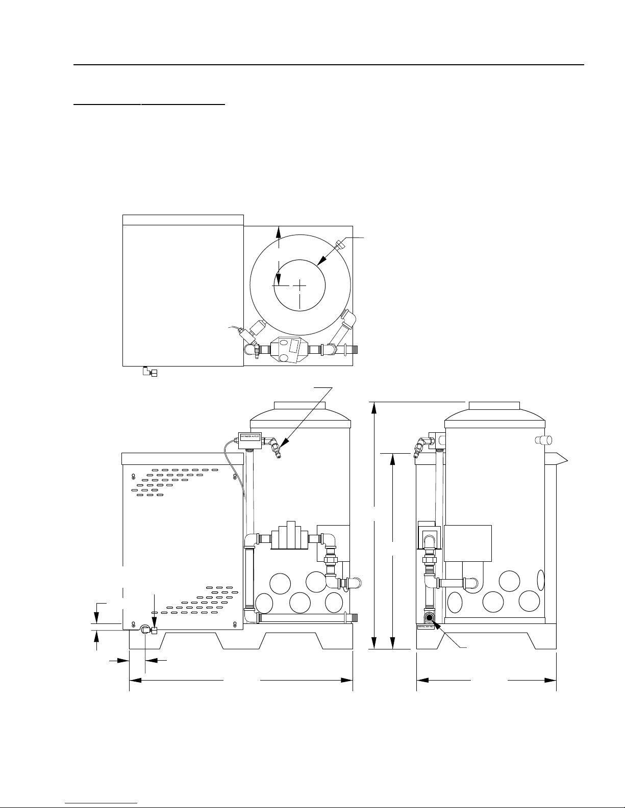
HNG SERIES PRESSURE WASHER
INSTALLATION GUIDE
HNG
9.57" I.D.
11-3/4"
OPERATOR’S MANUAL
5
Fresh Water
In 1.0" GHF
1-1/4"
3.0"
High Pressure Out
44-1/4"
49-0"
38-3/8"
Gas In
1-1/2" NPT-M
27-1/2"
Shark HNG • Rev. 2/03a
6
HNG SERIES PRESSURE WASHER
OPERATOR’S MANUAL
machine should be located considering accessibility for the replacing of components and the refilling
of detergents, adjustments and maintenance. Normal precautions should be taken by the operator of
the machine to prevent excess moisture from reaching the power unit or electrical controls.
2. It is recommended that a partition be made between
the wash area and the machine to prevent direct
spray from the spray gun from coming in contact with
the machine. Excess moisture reaching the power
unit or electrical controls will reduce the machine’s
life and may cause electrical shorts.
3. During installation of the machine, beware of poorly
ventilated locations or areas where exhaust fans may
cause an insufficient supply of oxygen. Sufficient
combustion can only be obtained when there is a
sufficient supply of oxygen available for the amount
of fuel being burned. If it is necessary to install a
machine in a poorly ventilated area, outside fresh
air may have to be piped to the burner and a fan
installed to bring the air into the area.
4. Do not locate near any combustible material. Keep
all flammable material at least 20 feet away.
Allow enough space for servicing the machine.
Local code will require certain distances from floor
and walls. (Two feet away should be adequate).
WARNING: Avoid small areas or near exhaust fans.
Gas Codes:
Confer with local gas company and with proper municipal officials regarding any specific code or regulations
governing the installation. The installation must conform
to local codes.
Electrical:
The machine, when installed, must be electrically
grounded in accordance to local codes. Check for proper
power supply using a volt meter; check the serial plate
for the correct requirements.
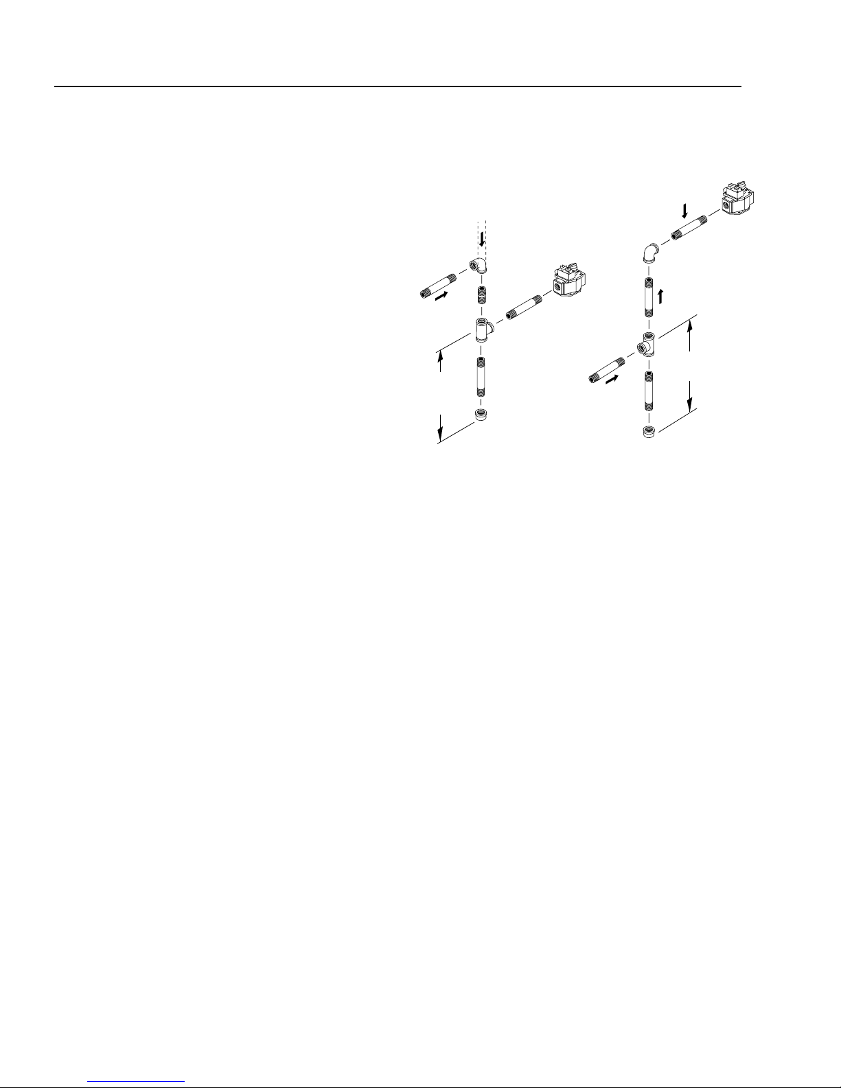
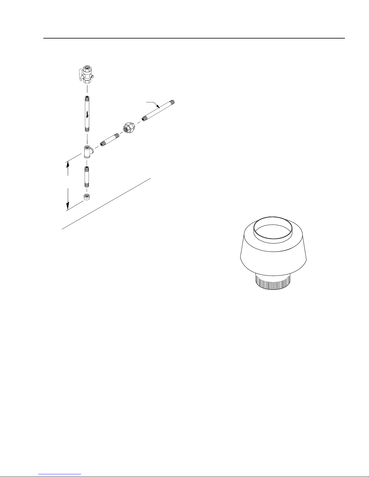
Gas Piping:
Figure 1
Drop
Gas
Valve
3" (7.62 mm)
Minimum
DRIP LEG
Sediment trap (drip leg) must be
installed in the supply line.
Install a union in the gas line adjacent to and upstream
from the control manifold and downstream from the
manual main shut-off valve. A 1/8" NPT plugged tapping
accessible for test gauge connection shall be installed
immediately upstream of the gas supply connection for
the purpose of determining the gas supply pressure to
the burner, and to prevent damage to gas valve.
If a manual gas shut off valve is not in the gas supply line
within six feet of the machine and in an accessible location, one shall be installed.
1/4" Test Port
(6" - 14 W.C.
or 1/2" PSIG)
Gas
Valve
3" (7.62 mm)
Minimum
Shark HNG • Rev. 2/03a
HNG SERIES PRESSURE WASHER
OPERATOR’S MANUAL
7
Figure 2
Manual
Shut-Off Valve
3" (7.62 mm)
Minimum
Flow
Tee
1/8" NPT Plugged
Pressure Gauge
Port Location
Control Manifold
Pipe
Cap
Floor Level
Union
To
Gas Valve
Input - BTU Per Hour Draft Hood & Flue Pipe Size
250,000 - 320,000 8 inch
320,000 - 410,000 9 inch
410,000 - 600,000 10 inch
600,000 - 750,000 12 inch
NOTE: If the flue pipe exceeds 10 ft. in length, or contains more than two elbows, use next size larger pipe
and draft hood or the burner will not ignite. No movable
flue pipe damper should be used on any installation.
Draft Diverter:
Install the draft diverter above the heating coil. The
diverter enhances the draft through the burner by severing the chimney effect created in sections of furnace pipe
positioned below. It also helps prevent freezing of the
coil due to wind chill factors.
Figure 3
Optional
UNION LOCATION
The following pipe and stack sizes are just recommendations. Always consult a local plumber and venting contractor for local codes and regulations during installation.
Distance From Regulator Pipe Size
0 - 59' 1" 1 PS
50' - 100' 1-1/2" 1 PS
100' - 200' 1-3/4" 1 PS
Natural Gas
Distance From Regulator Pipe Size
0 - 50' 1-1/2" 1 PS
50' - 100' 2" 1 PS
100' - 200' 2-1/2" 1 PS
Venting:
If the machine is used indoors, regulations or ventilation
concerns may call for a chimney or furnace pipe.
When venting the machine, if the machine is to be in an
enclosed area with a chimney on it, be sure the chimney
is the same size as the stack on the machine. Poor draft
will cause the machine to soot and not operate efficiently.
When placing the machine for installation, position the
stack to be as straight as possible and to protrude through
the roof of the building at a proper location and at sufficient height to eliminate down-draft. The chimney of a
gas fired machine shall be installed with a down-draft
diverter located about 3 ft. above machine.
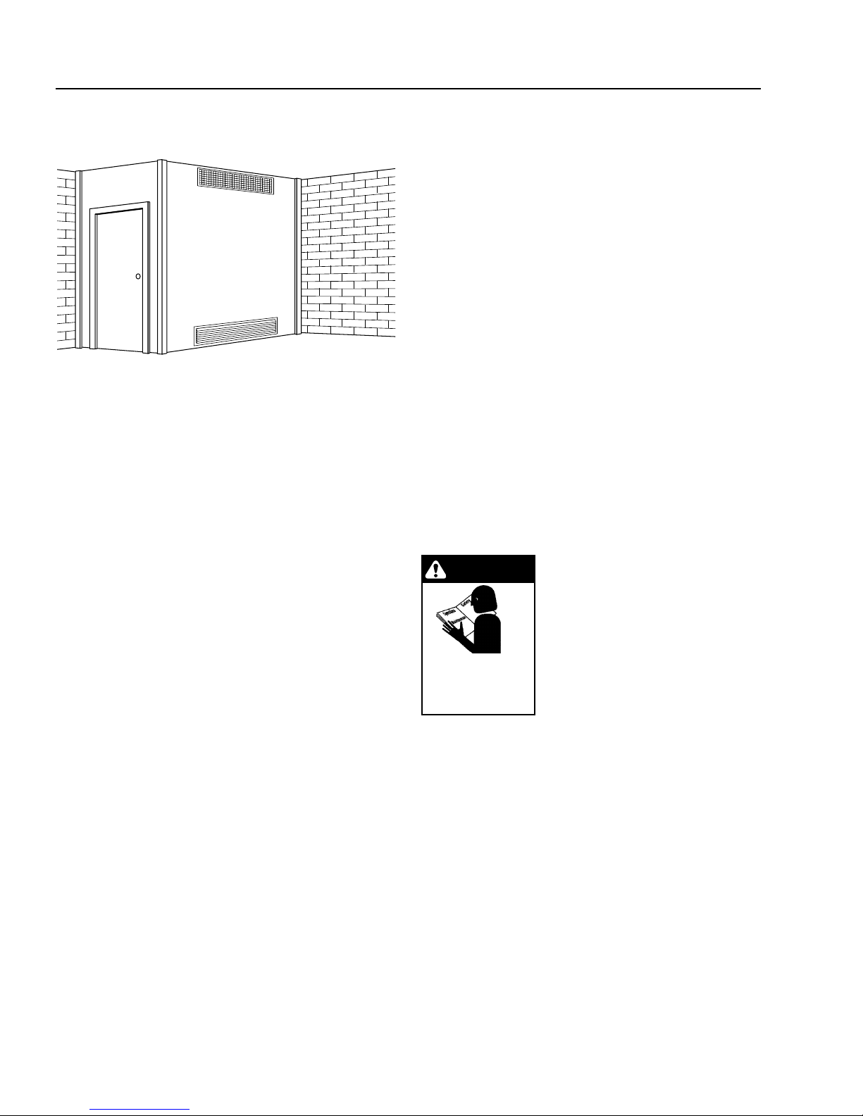
When the heating appliance is installed in a tightly closed
room without ventilation openings to the outdoors or other
rooms, provisions shall be made for supplying air for combustion through special openings, one near the floor line
and the other near the ceiling, each to be sized on the
basis of one square inch or more of free area for each
1,000 BTU input per hour (see Figure 4).
When a room is of unusually tight construction and has
a kitchen and/or bathroom ventilating fan, which may be
used for exhausting air outdoors -or has a vented fireplace — it is recommended that combustion air be supplied to the enclosed room through intakes extending to
the outside of the building and terminating in down-turned
fittings. These should be suitably arranged to prevent obstruction from snow or rain, and include a protecting
screen not smaller than 1/4 inch mesh.
Shark HNG • Rev. 2/03a
8
HNG SERIES PRESSURE WASHER
OPERATOR’S MANUAL
Figure 4
Ventilating Air Opening.
1 square inch for each
1000 BTU per hour input.
Illustration showing air openings necessary
to supply air for combustion when installed
in an enclosed room.
Water Source:
The water source for the machine should be supplied by
a 5/8" I.D. garden hose with a city water pressure of not
less than 30 PSI. If the water supply is inadequate, or if
the garden hose is kinked, the machine will run very rough
and the burner will not fire.
Water Connection:
Connect the high pressure hose by pulling the coupler
collar back and then inserting it onto the discharge nipple.
Secure it by pushing the collar forward.
Attach the wand into the spray gun using teflon tape on
the pipe threads to avoid leaks.
Inspection and Testing Gas Piping:
The building structure should not be weakened by installing the gas piping. The piping should not be supported by other piping, but should be firmly supported
with gas hooks, straps, bands or hangers. Butt or lap
welded pipe should not be run through or in an air duct
or clothes chute.
Before turning gas under pressure into piping, all openings from which gas can escape should be closed. Immediately after turning on gas, the system should be
checked for leaks. This can be done by watching the 1/2
cubic foot test dial for 5 minutes for any movement or by
soaping each pipe connection and watching for bubbles.
If a leak is found, make the necessary repairs and repeat the above test.
Shark HNG • Rev. 2/03a
Defective pipes or fittings should be replaced and not
repaired. Never use a flame or fire in any form to locate
gas leaks — use a soap solution.
After the piping and meter have been checked completely,
purge the system of air. DO NOT bleed the air inside an
enclosed room.
During pressure testing of the system at test pressures
in excess of 1/2 PSIG, the appliance and its individual
shut-off valve must be disconnected from the gas supply piping system or damage to the gas valve will occur.
Gas Pressure:
The ideal incoming gas pressure is 11 water column
inches or w.c.i. (minimum 9 w.c.i, maximum 14 w.c.i. or
1/2 PSIG). The correct operating manifold pressure for
natural gas is 3.5 w.c.i. The operating manifold pressure
for propane gas is 10 w.c.i. By adjusting the gas valve
pressure regulator between 3 and 4 w.c.i. a side range
can be achieved for natural gas.
If the desired input rating cannot be obtained within the
above manifold pressure adjusting range, then the next
size larger or smaller burner orifice should be used.
START-UP
WARNING
READ SAFETY
INSTRUCTIONS
INSTALLING OR
TO
SERVICING
PRIOR
MACHINE
operating valves, pressure regulation, and automatic
shut-off valve for proper operation.
2. Install in a suitable dry location. The machine must
be located in an area properly protected from the
weather.
3. Shut off gas and electricity before starting installation or service. Turn back on to test or operate.
4. DO NOT connect appliances before pressure testing the gas piping. Damage to gas valve may result.
(9 - 14 w.c.i. or 1/2 PSIG)
5. DO NOT insert any object other than suitable pipe
or tubing in the inlet or outlet of the gas valve. Internal damage may occur and result in a hazardous
condition.
6. DO NOT grip gas valve body with a pipe wrench or
vise. Damage may result causing gas leakage. Use
inlet or outlet bosses or a special body wrench.
7. DO NOT short the gas valve terminals.
WARNING: Read and follow instructions carefully when installing or servicing machine. Failure
to do so may result in damage to
property or personal injury.
1. Installation or servicing of gas
appliances and controls must
.
only be performed by qualified
personnel. After installation or
servicing, test manual valve,

HNG SERIES PRESSURE WASHER
8. DO NOT allow any flame to impinge on the regulator vent tubing if supplied. It may clog and cause
gas valve malfunction.
9. DO NOT use the gas cock to adjust gas flow.
10. If main burner fails to shut off, turn off gas supply.
11. Keep all combustible materials away from gas appliances. DO NOT allow lint or dust to collect in burner
area.
12. Dials must only be operated by hand. Never use pliers, wrenches or other tools to turn dials.
13. Leak test with a soap solution after installation or
service with the main burner on. Coat pipe and tubing joints, gaskets, etc.
14. If the machine is installed in an enclosed room, care
should be taken to ensure that an adequate supply
of air is available for combustion and ventilation.
(1 sq. inch per 1000 BTU).
OPERATOR’S MANUAL
9
Shark HNG • Rev. 2/03a

10
HNG SERIES PRESSURE WASHER
OPERATOR’S MANUAL
CHECK LIST BEFORE
STARTING:
CAUTION! If “NO” is checked on any of the following
sixteen questions, do not operate this machine.
YES NO
Has gas supply been inspected by an
authorized contractor to meet local codes?
Is machine protected from downdraft and
excessive wind?
Is machine shielded from moisture or water
spray?
Is the voltage correct and are the circuit
breaker and supply cord adequate
according to s pecifications and serial plate
notation?
Is the machine electrically grounded?
Is there ample water su pply?
Have all flammable liquids or gases been
removed from installation location?
Is there adequate gas supply for the BTU
rating of the burner?
Is incoming gas supply press ure between
6 - 14 water column inches or 1/2 PSIG?
FOR YOUR SAFETY READ BEFORE LIGHTING
WARNING
If you do not follow these instr uctions exactly, a fire or
explosion may result, causing p roper ty damag e, persona l
injury or loss of life.
A. This appliance has a pilot which must be lighted by hand.
When lighting the pilot, follow these instructions exactly.
B. BEFORE LIGHTING smell all a round the appliance area
for gas. Be sure to smell nex t to the floor because some
gas is heavier tha n air and will settle on the floor.
FOR YOUR SAFETY
"WHAT TO DO IF YOU SMELL GAS"
• Do not try to light any appliance.
• Do no t touch any electrical switch, do not use any phone
in your building.
• Immediately call you r gas supplier from a neighbor's
phone. Follow the gas supplier's instructions.
• If you cannot reach your supplier, call the fire department.
C. Use only your hand to push in or turn the gas control
knob. Never use tools. If the knob will not push in or turn
by hand, don't try to repair it; call a qualified service
technician. Forced or attempted repair may result in a fire
or explosion.
Has the proper gas regulator been
installed for pressure and volume?
Is the machine properly vented to allow
adequate air flow?
Are the propane tanks large enough,
according to rating to prevent freezing?
Have gas lines been checked for gas
leaks?
Have gas lines been checked with local
codes?
Have all operators using this machine
been instructed properly & have they read
the manual?
Has the machine been installed acco rding
to operator's manual instructions?
D. Do not use this appliance if any part has be en under
water. Immediately call a qualified service technician to
inspect the appliance and to replace any part of the
control system and any gas control which has been
under water.
Shark HNG • Rev. 2/03a
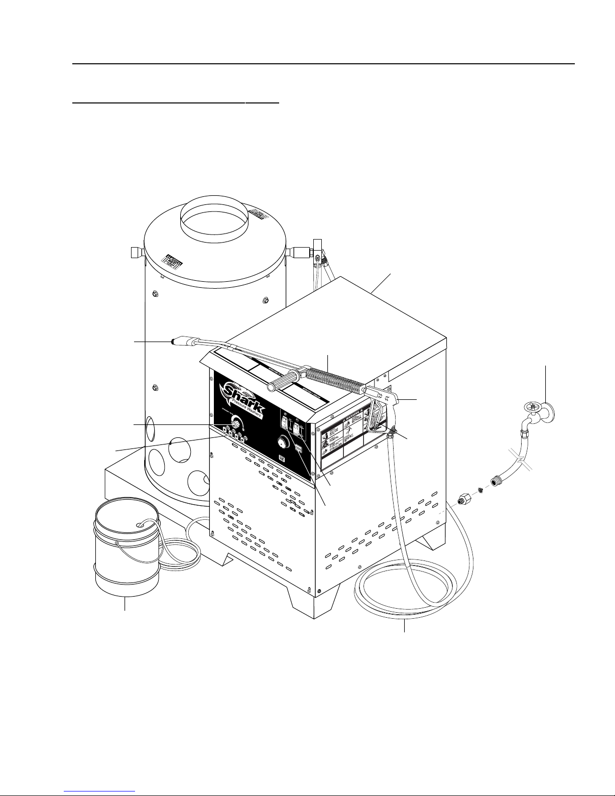
HNG SERIES PRESSURE WASHER
COMPONENT IDENTIFICATION
OPERATOR’S MANUAL
Main Gas
Supply Inlet
11
Wand Quick
Coupler
Detergent
Valve
Pressure
Nozzle
Detergent Bucket
(optional)
Spray
Wand
Pump
Switch
Burner
Switch
Trigger
High Pressure
Hose
Water Supply
(not included)
Spray
Gun
Shark HNG • Rev. 2/03a

12
HNG SERIES PRESSURE WASHER
OPERATOR’S MANUAL
OPERATING INSTRUCTIONS
WARNING
READ OPERATOR’S
THOROUGHLY
MANUAL
4. Connect the water supply hose to the inlet connec-
5. Have an electrician connect power supply into junc-
6. Turn on the main gas supply.
7. Partially depress and turn control knob to the “OFF”
8. Wait five minutes to allow gas, which may have ac-
9. Turn gas cock dial to “PILOT” position.
10. Depress the control knob all the way and hold it in.
11. Release dial and turn to full "ON".
12. Attach the desired high pressure nozzle into the wand
13. Push "ON" switch, or turn to pump position and pull
14. To activate the gas control valve for hot water, push
15. To apply detergent, open the detergent valve counter-
TO USE .
PRIOR
tor and turn the water on. Check for water leaks and
tighten as needed.
tion box according to information shown on the serial plate.
position (see fig.5 on page 14).
cumulated in the main burner compartment, to escape.
After five (5) seconds, depress the red ignitor until
you hear a loud click. Repeat 3 or 4 times if necessary until pilot is lit. If pilot does not remain lit, repeat
the operation allowing a longer period of time before
releasing the gas valve knob. After the pilot lights,
continue to hold the control knob down for about one
(1) minute before releasing.
NOTE: Sufficient time must be allowed for a proper
size pilot flame to heat the thermocouple and hold
the safety magnet in a locked-up position. Also, time
must be allowed for air to escape from the lines during the first operation.
quick coupler by pulling the coupler collar back and
then inserting the nozzle and securing it by pushing
the coupler collar forward.
the trigger on the spray gun allowing cold water to
flow.
the burner switch to the "ON" position and pull the
trigger on the spray gun.
clockwise making sure that the detergent pick up
tube is in the detergent solution and not sucking air.
WARNING: STOP! Read operators manual before operating this
machine.
1. Failure to read operation and
warning instructions may result
in personal injury or property
damage.
2. Turn all switches off.
3. Review installation instructions.
16. To Stop: Turn the burner switch "OFF" and place
the detergent pick up tube into fresh water. Open
the detergent valve and spray gun allowing detergent lines to be flushed and the burner to cool. Otherwise coil damage will result.
17. After water has cooled, push or turn pump switch to
OFF position. If the machine is going to be off for an
extended period of time, put the gas cock dial on the
gas valve into the “OFF” position.
18. Turn water off. Prevent from freezing.
PREVENTATIVE
MAINTENANCE
1. Check to see that the water pump is properly lubricated.
2. Follow winterizing instructions to prevent freeze damage to the pump and coils.
3. Always neutralize and flush detergent from system
after use.
4. If water is known to be high in mineral content, use a
water softener in your water system or descale as
needed.
5. Do not allow acidic, caustic or abrasive fluids to be
pumped through system.
6. Always use high grade quality Shark cleaning
products.
7. Never run pump dry for extended periods of time.
8. Periodically delime coils as per instructions.
It is advisable, periodically, to visually inspect the burner.
Check air inlet to make sure it is not clogged or blocked.
Wipe off any oil spills and keep this equipment clean
and dry.
The areas around the Shark washer should be kept clean
and free of combustible materials, gasoline and other
flammable vapors and liquids.
The flow of combustion and ventilating air to the burner
must not be blocked or obstructed in any manner.
GENERAL WASHING
TECHNIQUES
If dirt comes off relatively easy and no grease and oil are
present, cleaning with cold water will normally suffice.
However, when grease and oil are present, hot water
will greatly speed up the process.
Clean with the spray nozzle a foot or so from the surface
being cleaned. For more difficult cleaning, move the
nozzle in closer.
Shark HNG • Rev. 2/03a
 Loading...