

Page 1

MODEL: HE
OPERATING INSTRUCTION
AND PARTS MANUAL
■ HE-2010 ■ HE-2015
For technical assistance or the SHARK dealer nearest you, call 1-800-771-1881
or visit our website at www.shark-pw .com
97-717
Page 2

CONTENTS
Important Safety Information................................................................3-4
Component Identification ........................................................................ 5
Assembly Instructions.............................................................................6
Operating Instructions............................................................................. 7
Applying Detergent and General Operating Techniques..........................8
Shut Down and Clean-Up ....................................................................... 9
Storage ................................................................................................... 9
Troubleshooting .................................................................................... 10
Prev entative Maintenance..................................................................... 11
Oil Change Record ............................................................................... 11
Exploded View ...................................................................................... 12
Exploded View Parts List ...................................................................... 13
Hose and Spray Gun Assembl y............................................................ 14
Downstream Injector............................................................................. 14
Warranty
Model Number ______________________________
Serial Number ______________________________
Date of Purchase ____________________________
The model and serial numbers will be found on a decal attached to
the pressure washer. You should record both serial number and
date of purchase and keep in a safe place f or future reference.
2
96-723, 97-715, 97-716, 97-717 • REV. 2/04
Page 3
INTRODUCTION
Thank you for purchasing a Pressure Washer.
All information in this manual is based on the latest prod-
uct information availab le at the time of printing.
We reserve the right to make changes at any time with-
out incurring any obligation.
This machine was designed for maximum
use of 1 hour a day, 5 days a week.
Owner/User Responsibility:
The owner and/or user must hav e an understanding of
the manufacturer’ s operating instructions and warnings
before using this pressure washer . W arning information
should be emphasized and understood. If the operator
is not fluent in English, the manufacturer’s instructions
and warnings shall be read to and discussed with the
operator in the operator’s native language by the purchaser/owner, making sure that the operator comprehends its contents.
Owner and/or user must study and maintain for future
reference the manufacturers’ instructions.
This manual should be considered a permanent
part of the machine and should remain with it if
machine is resold.
When ordering parts, please specify model and
serial number .
IMPORTANT SAFETY
INFORMATION
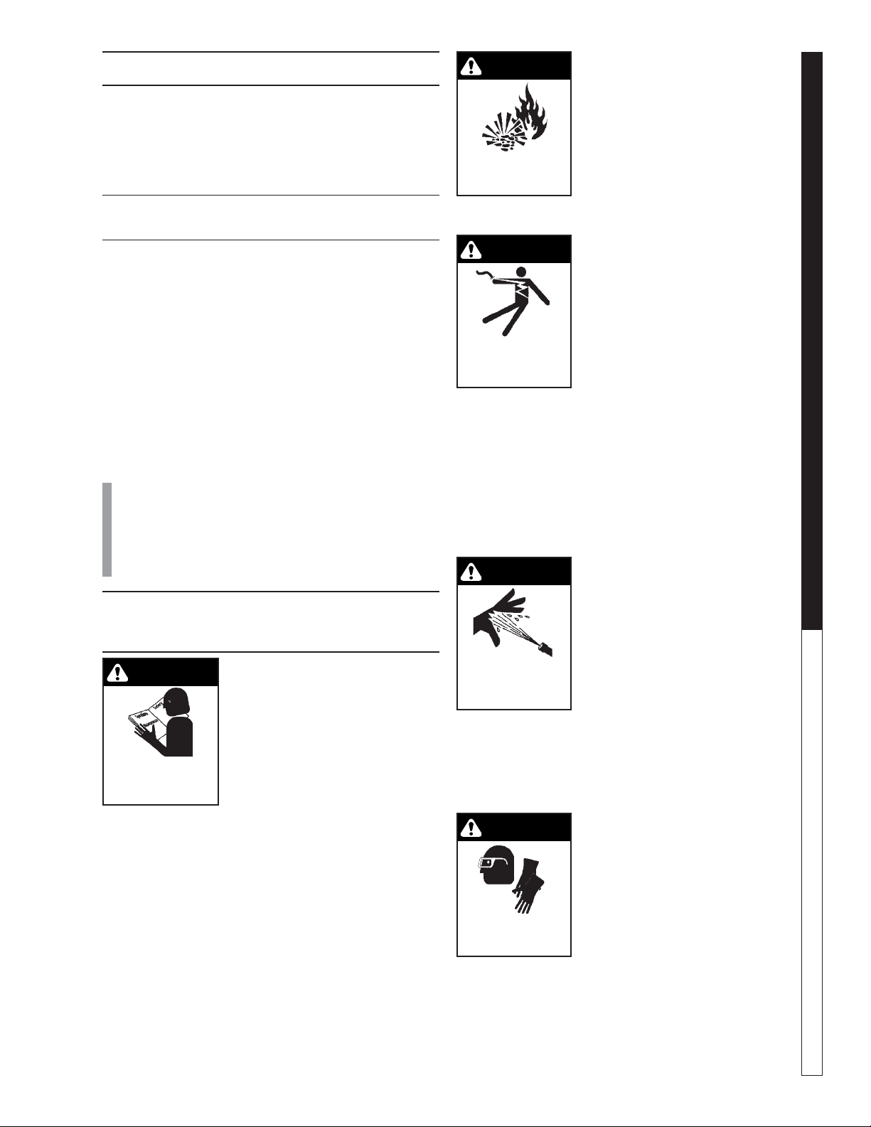
WARNING
READ OPERA TOR’S
MANUAL THOR OUGHLY
PRIOR TO USE.
2. Know how to stop the machine and bleed pressures
quickly. Be thoroughly f amiliar with the controls.
3. Stay alert – watch what your are doing.
4. All installations must comply with local codes. Contact your electrician, plumber, utility company or the
selling distributor for specific details. To comply with
the National Electrical code (NFP A 70) and provide
additional protection from risk of electric shock, this
pressure washer is equipped with a UL approved
ground fault circuit interrupter (GFCI) power cord.
WARNING: To reduce the risk of
injury, read operating instructions carefully before using.
1. Read the owner's manual thoroughly. Failure to follow instructions could cause malfunction of the machine and
result in death, serious bodily
injury and/or property damage.
96-723, 97-715, 97-716, 97-717 • REV. 2/04
WARNING
WARNING: Flammable liquids
can create fumes which can ignite, causing property damage or
severe injury . Do not spra y flammable liquids.
RISK OF EXPLOSION:
DO NOT SPRAY
FLAMMABLE LIQUIDS.
5. Risk of explosion - do not spra y
flammable liquids or operate in
an explosiv e location. Operate
only where open flame or torch
is permitted.
WARNING
WARNING: Keep water spray
away fr om electrical wiring or fatal electric shock may result.
6.
WARNING: To protect the
operator from electrical
shock, the mac hine must be
KEEP WA TER
SPRAY AWAY FROM
ELECTRICAL WIRING.
electrically grounded. It is
the responsibility of the
owner to connect this machine to a UL grounded
receptacle of proper v oltage and amperage ratings. Do not spray water on or near electrical
components. Do not touch machine with wet
hands or while standing in water. Always disconnect power before servicing.
7. Grip cleaning wand securely with both hands before starting the pressure washer. F ailure to do this
could result in injury from a whipping wand.
WARNING
WARNING: Equipment can produce a high pressure stream of
fluid that can pierce skin and its
underlying tissues, leading to serious injury and possible ampu-
HIGH PRESSURE
STREAM CAN
PIERCE SKIN AND
TISSUES.
tation.
8. High pressure developed by
these machines will cause personal injury or equipment
damage. Use caution when operating. Do not direct discharge stream at people, or severe injury or
death will result.
9. Never make adjustments on machine while in operation.
WARNING
WARNING: High pressure can
cause paint chips or other particles to become airborne and fly
at high speeds.
10. Eye safety devices, foot pro-
USE PROTECTIVE
CLOTHING WHEN
OPERATING.
tection and protective clothing
must be worn when using this
equipment.
11. Machines with spray gun should not be operated
with the trigger in the off position for extensive periods of time as this may cause damage to the pump.
12. The best insurance against an accident is precaution and knowledge of the machine.
PRESSURE WASHER
OPERATOR’S MANUAL
3
Page 4

13. We will not be liable for any changes made to our
standard machines, or any components not purchased from us.
14. Be certain all quick coupler fittings are secured before using pressure washer .
15. Never run pump dry or leave spray gun closed
longer than 5 minutes.
16. T o reduce the risk of injury , close supervision is necessary when a machine is used near children. Do
not allow children to operate the pressure washer .
This machine must be attended during opera-
PRESSURE W ASHER
tion.
17. Protect from freezing.
18. When the machine is working, do not cover or place
in a closed space where ventilation is insufficient.
OPERATOR’S MANUAL
4
96-723, 97-715, 97-716, 97-717 • REV. 2/04
Page 5
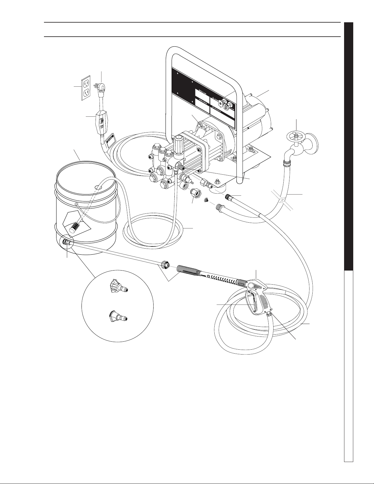
Plug
(120V)
PRESSURE WASHER
COMPONENT IDENTIFICATION
Power
Supply
GFCI
Detergent Bucket
(not included)
Nozzle
Quick
Coupler
Wand
Oil Dip
Stick
Inlet
Connector
Pick-up T ube
Detergent
Discharge
Nipple
Quick Coupler
Spray
Gun
Electric
Motor
Water
Faucet
OPERATOR’S MANUAL
Water Supply
Hose
(not included)
Pressure Nozzle
Brass Soap
Nozzle
Detergent Injector - Allows you to siphon and mix de-
tergents.
High Pressure Hose - Connect one end to water pump
discharge nipple and the other end to spray gun.
Nozzle Quick Coupler Pump - Develops high pressure.
Spray Gun - Controls the application of water and de-
tergent onto cleaning surface with trigger device. Includes safety latch.
96-723, 97-715, 97-716, 97-717 • REV. 2/04
Trigger
High
Pressure
Hose
Swivel
Connector
Swivel Connector - Allows free range of movement to
avoid coiling hoses.
Wand - Must be connected to the spra y gun.
Note: If trigger on spray gun is released for more
than 2 minutes, water will leak from valve. Warm
water will discharge from pump protector onto floor .
This system prevents internal pump damage.
5
Page 6

ASSEMBLY INSTRUCTIONS
Spray
Gun
Safety
Latch
PRESSURE W ASHER
STEP 1: Attach the high
High Pressure
Hose
pressure hose to the spray
gun using teflon tape on
hose threads.
Pressure
Nozzle
OPERATOR’S MANUAL
Wand
Collar
Wand
Coupler
STEP 4: Release the coupler col-
lar and push the nozzle until the
collar clicks. Pull the nozzle to
make sure it is seated properly.
Nozzle
Extension
Spray Gun/
Wand
STEP 2: Attach nozzle extension to spray
gun/wand. Tighten both by hand.
Dipstick
STEP 5: Remove shipping cap and
install oil dipstick. Check pump oil
lev el b y using dipstic k. Use 30 wt.
non detergent oil.
Pressure
Nozzle
Wand
Coupler
STEP 3: Pull the spring-loaded col-
lar of the wand coupler back to insert your choice of pressure nozzle.
Pump
Discharge
Fitting
High
Pressure
Hose
Coupler Collar
STEP 6: Connect the high pressure
hose to the pump discharge fitting.
Push coupler collar forward until
secure.
Cold
Water
Source
Garden
Hose
STEP 7: Connect garden hose to
the cold water source.
Pump
Water Inlet
Garden
Hose
STEP 8: Connect the garden hose to pump water inlet. In-
spect inlets.
CAUTION: Do not run the pump without wa-
ter or pump damage will result.
6
96-723, 97-715, 97-716, 97-717 • REV. 2/04
Page 7

OPERATING INSTRUCTIONS
Cold
Water
Source
Garden
Hose
STEP 1: Connect garden hose to the
cold water source and turn water on
completely. Nev er use hot w ater.
STEP 2: T rigger the spray gun to
eliminate trapped air then wait f or
a steady flow of water to emerge
from the spray nozzle.
STEP 4: Connect to appropriate power supply.
PRESSURE WASHER
OPERATOR’S MANUAL
STEP 4: Tur n machine on by flipping
switch at rear of motor .
NOZZLES
Safety
Latch
WARNING! Never replace
nozzles without engaging the
safety latch on the spray gun trigger.
The two color-coded quick connect nozzles are
easily accessible when placed in the convenient rubber nozzle holder, which is provided
on the front of the machine.
NOTE: To rinse, select the yello w. To apply detergent select the black nozzle.
96-723, 97-715, 97-716, 97-717 • REV. 2/04
7
Page 8

DETERGENTS AND GENERAL OPERATING TECHNIQUES
WARNING
PRESSURE W ASHER
OPERATOR’S MANUAL
STEP 2: Apply safety latch to spra y gun trigger. Secure
black detergent nozzle into quick coupler. NOTE: De-
tergent cannot be applied using the Yellow nozzle.
IMPORT ANT : You m ust flush the detergent injection
system after each use by placing the suction tube
into a bucket of clean water, then run the pressure
washer in low pressure for 1-2 minutes.
WARNING: Some detergents
may be harmful if inhaled or ingested, causing severe nausea,
fainting or poisoning. The harmful elements may cause property
damage or severe injury .
STEP 1: Use detergent designed
specifically for pressure washers.
Household detergents could damage the pump. Prepare detergent
solution as required by the manufacturer . Fill a container with pressure washer detergent. Place the
filter end of detergent suction tube
into the detergent container.
STEP 3: With the engine running, pull trigger to operate machine. Liquid detergent is
drawn into the machine and
mixed with water . Apply detergent to work area. Do not allow detergent to dry on surface.
THERMAL PUMP PROTECTION
pump protector engages and cools the pump by discharging the warm water onto the ground. This thermal
device prev ents internal damage to the pump .
CLEANING TIPS
Pre-rinse cleaning surface with fresh water . Place detergent
suction tube directly into cleaning solution and apply to surface at low pressure (for best results , limit your work area to
sections approximately 6 feet square and alw a ys apply detergent from bottom to top). Allow detergent to remain on
surface 1-3 minutes. Do not allow detergent to dry on surface. If surface appears to be drying, simply wet down surface with fresh water . If needed, use brush to remove stubborn dir t. Rinse at high pressure from top to bottom in an
even sweeping motion keeping the spray nozzle approximately 1 foot from cleaning surface . Use overlapping strok es
as you clean and rinse any surface. For best surface cleaning action spray at a slight angle.
Recommendations:
• Before cleaning any surface, an inconspicuous
area should be cleaned to test spray pattern and
distance for maximum cleaning results.
• If painted surfaces are peeling or chipping, use
extreme caution as pressure washer ma y remove
the loose paint from the surface.
• Keep the spray nozzle a safe distance from the
surface you plan to clean. High pressure wash a
small area, then check the surface for damage. If
no damage is found, continue to pressure washing.
CAUTION - Never use:
• Bleach, chlorine products and other corrosive
chemicals
• Liquids containing solvents (i.e., paint thinners,
gasoline, oils)
• Tri-sodium phosphate products
• Ammonia products
• Acid-based products
These chemicals will harm the machine and will damage the surface being cleaned.
RINSING
• It will take a fe w seconds f or the detergent to clear .
Apply safety latch to spray gun. Remov e black soap
nozzle from the quick coupler . Select and install the
desired high pressure nozzle. NOTE: You can also
stop detergent from flowing by simply removing detergent siphon tube from bottle.
If you run the engine on your pressure washer for 3-5
minutes without pressing the trigger on the spray gun,
circulating water in the pump can reach high temperatures. When the water reaches this temperature, the
8
96-723, 97-715, 97-716, 97-717 • REV. 2/04
Page 9

SHUTTING DO WN AND CLEAN-UP
CAUTION
PRESSURE WASHER
STEP 1: Remove de-
tergent suction tube
from container and insert into one gallon of
fresh water. Slide
nozzle forward f or lo w
pressure or to connect
black detergent
nozzle. Pull trigger on
spray gun and siphon
water for one minute .
Pump
Water
Inlet
STEP 5: Disconnect the garden
hose from the water inlet on the
machine.
STEP 2: Turn off machine by
flipping switch on rear of motor.
STEP 3: Turn off water supply .
High
Pressure
Outlet
STEP 6: Disconnect the high
pressure hose from high pressure outlet.
STEP 4: Press trigger
to release water pressure.
OPERATOR’S MANUAL
Safety
Latch
STEP 7: Engage
the spray gun
safety lock.
STORAGE
Pump Storage
CAUTION: Always store your pressure washer in a location where the
temperature will not fall below 32° F
(0° C). The pump in this machine is
susceptible to permanent damage if
frozen.
FREEZE DAMA GE IS NOT CO VERED
BY WARRANTY .
If you must store your pressure washer in a location
where the temperature is below 32° F, you can minimize the chance of damage to your machine by draining your machine as follo ws:
1. Stop the pressure washer and detach supply hose
and high pressure hose. Squeeze the trigger of the
spray gun to drain all water from the wand and
hose.
2. Restart pressure washer and let it run briefly (about
5 seconds) until water no longer discharges from
the high pressure outlet.
96-723, 97-715, 97-716, 97-717 • REV. 2/04
9
Page 10

TROUBLESHOOTING
PROBLEM POSSIBLE CAUSE SOLUTION
PUMP RUNNING
NORMALLY BUT
PRESSURE LOW ON
INSTALLA TION
FLUCTUATING
PRESSURE
PRESSURE LOW AFTER
PERIOD OF NORMAL USE
PUMP NOISY
PRESSURE WASHER Troubleshooting Guide
PRESENCE OF WATER IN
PUMP OIL
WATER DRIPPING FROM
UNDER PUMP
WATER DRIPPING FROM
PUMP PROTECTOR
OIL DRIPPING
EXCESSIVE VIBR ATI ON I N
HIGH PRESSURE HOSE
MOTOR DOES NOT START
WHEN SWITCHED ON
WHEN SWITCHING ON
THE MACHINE, MOTOR
HUMS BUT DOES NOT
RUN
MOTOR ST OPS
Pump sucking air Check water supply and possibility of air seepage.
Check valves sticking Check and clean or replace if necessary.
Unloader valve seat faulty Check and replace if necessary.
Nozzle incorrectly sized Check and replace if necessar y.
Worn piston packing Check and replace if necessary.
Valves worn Check and replace if necessary.
Blockage in valve Check and replace if necessary.
Pump sucking air Check water supply connections.
Worn piston packing Check and replace if necessary.
Insufficient water Check filter and hose for breakage.
Nozzle worn Check and replace if necessary.
Suction or delivery valves worn Check and replace if necessary.
Suction or delivery lines blocked Check and clean if necessar y.
Unloader valve seat worn Check and replace if necessary.
Worn piston package Check and replace if necessary.
Water temperature excessive Reduce to below 140
Air in suction line Check water supply and connections on suction line.
Broken or weak suction or delivery valve
spring.
Foreign matter in valves Check and clean if necessary.
Worn bearings Check and replace if necessary.
Water temperature excessive Reduce to below 160
Oil seal worn Check and replace if necessary.
High humidity in air Check and replace if necessary.
Piston packing wor n Check and replace if necessary.
Piston packing wor n Check and replace if necessary.
O-ring plunger retainer worn Check and replace if necessary.
Water supply pressure too high
(over 90 psi)
Spray gun i s in the off position for over 5
minutes
Oil seal worn Check and replace if necessary.
Irregular functioning of the pump valves Check and replace if necessary.
Plug not well connected or lack of power
supply
Main voltage is insufficient, lower than the
minimu m r e qu i r ed .
The pump is stuck or frozen Check by tur ning the motor manually.
Tripped thermal overload due to
overheating
Check and replace if necessary.
Lower water supp l y pr ess ur e us i n g r egu l at or.
Turn machine off if not in use for over 5 minutes.
Check plug, cable and switch.
Check to make sur e mai n power su p pl y i s
adequate.
Check that main voltage corresponds to specifications
for the machine. Wait a few minutes before turning on
the machine again by resetting the GFCI on the cord.
o
F.
o
F.
10
96-723, 97-715, 97-716, 97-717 • REV. 2/04
Page 11

PREVENTATIVE MAINTENANCE
This pressure washer was produced with the best av ailable materials and quality craftsmanship. Howe ver , you as
the owner have certain responsibilities for the correct care of the equipment. Attention to regular preventative
maintenance procedures will assist in preserving the performance of your equipment. Contact your dealer for
maintenance. Regular preventativ e maintenance will add many hours to the life of y our pressure washer . P erform
maintenance more often under severe conditions .
PRESSURE WASHER
Pump Oil
Inspect Daily inspect the oil level
Change After first 50 hours, then every 500 hours or annually
Replace High Pressure Nozzle Every 6 months
Replace Quick Connects Anually
Clean Water Screen/Filter Weekly
Replace HP Hose Anually if there is any sign of wear
Grease Motor Every 10,000 hours or annually
General Inspection Inspect the motor at regular intervals, approximately every 500 hours of operation,
or every 3 months, whichever occurs first. Keep the motor clean and the ventilation
openings clear. The f ollowing steps should be perf ormed at each inspection:
WARNING: Do not touch electrical connections before you first ensure that power
has been disconnected. Electrical shock can cause serious or f atal injury . Only qualified personnel should attempt the installation, operation and maintenance of this
equipment.
1. Chec k that the motor is clean. Check that the interior and exterior of the motor
is free of dirt, oil, grease, water, etc. Oily vapor , paper pulp , te xtile lint, etc. can
accumulate and block motor v entilation. If the motor is not properly ventilated
overheating can occur and cause early motor failure .
2. Check all electrical connectors to be sure that they are tight.
Lubrication & Bearings Bearing grease will lose its lubricating ability over time, not suddenly. The lubricating
ability of a grease (over time) depends primarily on the type of grease, the size of the
bearing, the speed at which the bearing operates and the severity of the operating
conditions. Good results can be obtained if the following recommendations are used in
your maintenance program.
Type of Grease A high grade ball or roller bearing grease should be used. Recommended greases
standard service conditions are: Shell Dolium R (Factory installed) or Chevron SRI
OPERATOR’S MANUAL
Date Oil Chang ed
Month/Day/Year
OIL CHANGE RECORD
Estimated Operating
Hours Since La st
Oil Change
96-723, 97-715, 97-716, 97-717 • REV. 2/04
Date Oil Chang ed
Month/Day/Year
Estimated Operating
Hours Since La st
Oil Change
11
Page 12

EXPLODED VIEW
PRESSURE W ASHER
OPERATOR’S MANUAL
32
Models 201406D, 2015070
24
1
7
7
31
22
2
3
4
5
8
6
8
16
10
9
23
1
11
Models
201006D,
201007D,
2-11026D
13
12
14
15
27
33
34
35
30
34
36
28
29
25
19
20
18
14
21
13
26
17
13
14
25
14
14
21
12
96-723, 97-715, 97-716, 97-717 • REV. 2/04
Page 13

EXPLODED VIEW P ARTS LIST
PRESSURE WASHER
ITEM PART # DESCRIPTION QTY
1 6-01062 GFCI, 120V, 15 Amp w/36' 12-3
Cord (201006D, 201007D,
211026D) 1
6-01060 GFCI, 120V 20 Amp w/36' 12-3
Cord (201406D, 201507D) 1
2 6-03911 Lid, Plastic Carlon
(201406D, 201507D) 1
3 6-020204 Switch, 2 Pos. 120V-600V
(201406D, 201507D) 1
4 6-03910 Box, Plastic Carlon
(201406D, 201507D) 1
11-1042 ▲ Label, Ground 1
5 6-051595 Strain Relief, STRT, LQ Tite
Large (201406D, 201507D) 1
6-05172 ▲ Locknut, 3/4" 1
6 6-0104 Cord, Service, SOWA, 12/3
(201406D, 201507D) 2 ft.
7 90-1991 Screw, 10/32" x 1/2" BHSOC
(201406D, 201507D) 6
8 90-017 Nut, 10/32" Keps
(201406D, 201507D) 9
9 90-100030 Screw, 10-32" x 3/4" RH, SL,
BLK (201406D, 201507D) 1
10 95-07111118 Switch Box BRKT
(201406D, 201507D) 1
11 5-1046 Motor, 1.5 HP, 1 PH, 3450 RPM,
C-Face (201006D, 2-11026D,
201007D) 1
6-05152 ▲ Strain Relief, STRT, LQ TITE 3
(201006D, 201007D) 1
6-05181A ▲ Locknut, 1/2" (201006D,
201007D) 1
5-1047 Motor, 2 HP, 1 PH, 3450 RPM,
(201406D, 201407D) 1
6-0517 ▲ Strain Relief, 3/4"
(201406D, 201407D) 1
12 6-02049 Switch, Toggle, Assy (201006D,
201007D, 2-11026D) 1
13 90-2001 Nut, 5/16" ESNA, NC 8
14 90-4001 Washer, 5/16" Flat SAE 12
15 11-0350F Label, French Warning 1
16 11-0314 Label, Instr. (TE Models) 1
11-0311 Label, Instr. (HE Models) 1
10-99073 Label, Instr. (ZE Models) 1
11-0325 Label, Instr. (ET Models) 1
17 95-07200126 Handle Assy, Red (TE, HE,
ET Models) 1
95-07102116 Handle Assy, Black (Model
ZE) 1
18 4-16540 Nozzle, Compl. QCEM-6540
w/Blk Nylon (Soap Nozzle) 1
ITEM PART # DESCRIPTION QTY
19 4-12804015 Nozzle, SAQCMEG 1504
Yellow (201006D, 201007D,
2-11026D) 1
4-12803015 Nozzle, SAQCMEG 1503 Yellow
(201406D, 201507D) 1
20 2-0103 Grommet, Rubber, Nozzle
Holder 2
21 90-1006 Bolt, 5/16" x 3/4" NC 4
22 10-08021 Label, Disconnect Power 1
23 10-08018 Label, Warning, Service
Cord 1
24 6-05154 Strain Relief 90° (201406D)1
6-05181 ▲ Locknut, 1/2" Conduit
(201406D) 1
25 2-01023 Mount, Vibration, 5/16”-18 x
9/16” Stud, 30 Duro 4
26 10-08016 Label, Intended For Indoor
Use 1
27 10-9999 Label, Clear Lexan,
2-1/4" x 4-1/2" 1
28 2-300816 Pump Protector, 3/8" PTP 1
29 2-2006 Nipple, 3/8" x 3/8" NPT ST
Female 1
30 2-10943 Swivel, 3/8" MP x 3/4" (201001D,
201501D, 301001D) 1
31 90-4002 Washer, 3/8" Flat SAE 4
32 90-1016 Bolt, 3/8" x 1", NC 4
33 5-2107 Pump, Comet AXD2020E
(201006D, 201406D,
2-11026D) 1
5-1618 Pump, Legacy , WMH2521
(201007D, 201507D) 1
34 2-9040 Clamp, Hose UNI .46 - .54 2
35 4-02080000 Hose, 1/4” x 1/2” Clear
Vinyl 4 ft.
36 2-1904 Strainer, 1/4” Barb 1
OPERATOR’S MANUAL
96-723, 97-715, 97-716, 97-717 • REV. 2/04
13
Page 14

HOSE & SPRAY GUN ASSEMBLY
5
4
PRESSURE W ASHER
6
Pressure Nozzle
7
OPERATOR’S MANUAL
Brass Soap
Nozzle
HOSE & SPRAY GUN ASSEMBLY PARTS LIST
ITEM PART NO. DESCRIPTION QTY
1 2-2002 Coupler, 3/8" Female 1
2-0121 ▲ Quick Coupler O-Ring 1
2 4-0203030C Hose, 30' x 3/8" w/Coupler (ET,
ZE Models) 1
4-020930BSC Hose, 30’ x 3/8” w/Coupler (HE
TE Models) 1
3 4-011137 Spray Gun, Shut-Off (ET, ZE
Models) 1
4-01246 Spray Gun, Shut-Off (HE, TE
Models) 1
4 4-011106 Wand, Straight (ET, ZE
Models) 1
4-0110531 Wand, SS 15.5” (TE, HE
Models) 1
1
2
3
ITEM PART NO. DESCRIPTION QTY
5 2-2000 Coupler, 1/4” Female 1
2-0119 Quick Coupler O-Ring 1
6 4-12803015 Nozzle, 3.0 15° Yellow
(201406D, 201507D
2-11026D) 1
Nozzle, 4.0 15° Yellow (201006D,
201007D) 1
7 4-16540 Nozzle, Brass Soap 1
▲ Not Shown
14
96-723, 97-715, 97-716, 97-717 • REV. 2/04
Page 15

HE SERIES PRESSURE WASHER
WARRANTY
SHARK LIMITED NEW PRODUCT WARRANTY
PRESSURE WASHERS
WHA T THIS W ARRANTY COVERS
All SHARK PRESSURE WASHERS are warranted by SHARK to the original purchaser to be free from defects in materials and
workmanship under normal use, for the periods specified below . This Limited W arranty is subject to the e xclusions sho wn below ,
is calculated from the date of the original purchase, and applies to the original components only. Any parts replaced under this
warranty will assume the remainder of the part’s warranty per iod. This warranty applies to the original purchaser and is not
transferable.
LIMITED LIFETIME PARTS WARRANTY:
Components manufactured by SHARK, such as frames, handles, coil wraps, float tanks, and belt guards. Forged brass pump
manifold. All heating coils will have a three year warranty. Internal components on the oil-end of all pressure washer pumps will
have a seven year warranty.
ONE YEAR PARTS WARRANTY:
All other components, excluding normal wear items as described below, will be warranted for one year on parts. Warranty on
these parts will be for one year regardless of the duration of the original component manufacturer’s par t warranty.
WARRANTY PROVIDED BY OTHER MANUFACTURERS:
Motors, generators, and engines, which are warranted by their respective manufacturers, are serviced through these manuf acturers’ local authorized service centers. SHARK cannot provide warranty on these items.
WHAT THIS WARRANTY DOES NOT COVER
This warranty does not cover the following items:
1. Normal wear items, such as nozzles, guns, discharge hoses, wands, quick couplers, seals, filters, gaskets, O-rings,
packings, pistons, pump valve assemblies, strainers, belts, brushes, rupture disks, fuses, pump protectors.
2. Damage or malfunctions resulting from accidents, abuse, modifications, alterations, incorrect installation, improper
servicing, failure to follow manufacturer’s maintenance instructions, or use of the equipment beyond its stated usage
specifications as contained in the operator’s manual.
3. Damage due to freezing, chemical deterioration, scale buildup, rust, corrosion, or thermal expansion.
4. Damage to components from fluctuations in electrical or water supply.
5. Normal maintenance service, including adjustments, fuel system cleaning, and clearing of obstructions.
6. Transportation to service center, shop labor charges, field labor charges, or freight damage.
WHAT YOU MUST DO TO OBTAIN WARRANTY SERVICE
While not required for warranty service, we request that you register your SHARK pressure washer by returning the completed
registration card. In order to obtain warranty service on items, you must return the product to an Authorized SHARK Dealer,
freight prepaid, with proof of purchase, within the applicable warranty period. If the product is permanently installed, you must
notify your Authorized SHARK Dealer of the defect. The Authorized Dealer will file a claim, which must subsequently verify the
defect. In most cases, the part must be returned to SHARK freight prepaid with the claim. For warranty service on components
warranted by other manufacturers, the Authorized Dealer can help you obtain warranty service through these manufacturers’
local authorized service centers.
LIMIT A TION OF LIABILITY
SHARK’S liability for special, incidental, or consequential damages is expressly disclaimed. In no event shall SHARK’S liability
exceed the purchase price of the product in question. SHARK makes every effort to ensure that all illustrations and specifications are correct, however, these do not imply a warranty that the product is merchantable or fit for a particular purpose, or that
the product will actually conform to the illustrations and specifications. THE WARRANTY CONTAINED HEREIN IS IN LIEU OF
ALL OTHER WARRANTIES, EXPRESS OR IMPLIED, INCLUDING ANY IMPLIED WARRANTY OF FITNESS FOR A PARTICULAR PURPOSE. SHARK does not authorize any other party , including authorized Dealers, to mak e any representation or
promise on behalf of SHARK, or to modify the terms, conditions, or limitations in any way. It is the buyer’s responsibility to ensure
that the installation and use of SHARK products conforms to local codes. While SHARK attempts to assure that its products
meet national codes, it cannot be responsible for how the customer chooses to use or install the product.
SHARK PRESSURE WASHERS
1-360-833-9100 • 1-800-771-1881 • www.shark-pw.com
PRESSURE WASHER WARRANTY
SHARK HE • 97-717 • REV. 2/04
Page 16

Form #97-717 • Revised 2/04 • Printed in U .S.A.
 Loading...