

SGS Thomson Microelectronics TS824ILT-2.5, TS824AILT-2.5, TS824-2.5 Datasheet
TS824-2.5
HIGH THERMAL STABILITY
MICROPOWER SHUNT VOLTAGE REFERENCE
■ LOW Tc: 50 ppm/°C MAXIMUM
■ 2.5V OUTPUT VOLTAGE
■ LOW OPERAT ING CURRE NT: 60µA max @
25°C
■ HIGH PRECISION AT 25°C: ±0.5% AND
±1%
■ STABLE WHEN USED WITH CAPACIT IVE
LOADS
■ INDUSTRIAL TEMPERAT URE RANGE:
-40 to +85°C
DESCRIPTION
The TS824-2.5 is a low power shunt voltage
reference featuring a very low temperature
coefficient of 50ppm/°C as a maximum value.
Providing a 2.5V output vo lta ge, the TS824-2.5
operates over the industrial temperature range
(-40 to +85°C). Ideal for battery-powered
equipments whe re power conservation is critical,
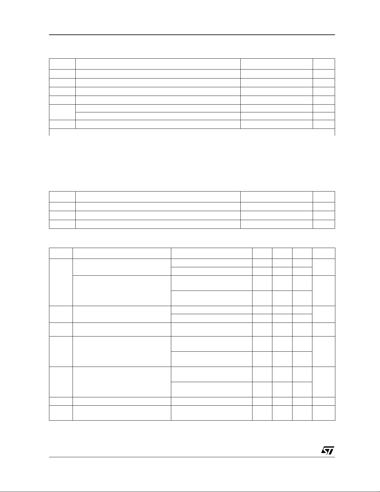
the TS824 is hous ed in a tiny SOT23-3 packa ge
allowing space saving.
The TS824 is typically stable with a ny capacitive
loads within the entire temperature range. The
product is thus easy to use and t he des ign simplified.
L
SOT23-3L
(Plastic Micropacka ge)
PIN CONNECTIONS (top view)
APPLICATION
■ Instrumentation,
■ Data acquisition systems,
■ Portable, Battery powered equipments
■ Power management
ORDER CODE
Voltage Precision SOT23-3
2.5V
Single temperature range: -40 to +85°C
LT = Tiny Package (SOT23- 3) - only available in Tape & Reel (LT)
March 2002
±1% TS824ILT-2.5 L252
±0.5% TS824AILT-2.5 L253
SOT23
Marking
1/5
TS824-2.5
ABSOLUTE MAXIMUM RATINGS
Symbol Parameter Value Unit
I
Reverse Breakdown Current 20 mA
K
I
Forward Current 10 mA
F
P
Power Dissipation (note1) SOT23-3 360 mW
D
T
ESD Human Body Model (HBM) (note2) 2 kV
T
Storage Temperature -65 to +150 °C
Std
Machine Model (MM) (note 2) 200 V
Lead Tempera ture (solde ring, 10 second s) 260 °C
Lead
Note 1: The maximum power dissipation mus t be derated at high temperat ure. It can be ca l culated using T
perat u re), R
temperature is P
Note 2: T he Human Body Model (H B M) is defined as a 100pF capacitor disc harge through a 1.5kΩ resistor into each pin.
The Machine Mode (MM) is defin ed as a 200pF capacitor discharge directly into each pins.
(Thermal resistance junction to ambient) and TA (Ambient temperature). The maximum power dissipation formula at any
THJA
DMAX
= (T
JMAX
- TA) / R
THJA. RTHJA
is 340°C/ W f or the SOT23-3 package.
(max i m um j un c tion tem-
JMAX
OPERATING CONDITIONS
Symbol Parameter Value Unit
I
I
T
Minimum Operating Current 60
min
Maximum Operating Current 15 mA
max
Operating Free Air Temperature Range -40 to +85 °C
oper
ELECTRICAL CHARACTERISTICS (note 3)
= 25°C (unless otherwise specified)
T
amb
Symbol Parameter Test Condition Min. Typ. Max. Unit
= 100µA, ±0.5%
I
Reverse Breakdown Voltage
V
K
Reverse Breakdown Voltage Tolerance
I
Minimum Operating Current
KMIN
Average Temperature Coefficient (note
/∆T
V
∆
K
5)
Reverse Breakdown Voltage Change
/∆I
V
∆
K
K
with Operating Current Range
R
Static Impedance
KA
K
Long Term Stability
VH
E
Wide Band Noise
N
K
= 100µA, ±1%
I
K
= 100µA, ±0.5%
I
K
-40°C < T
I
= 100µA, ±1%
K
-40°C < T
= 25°C
T
amb
-40°C < T
< +85°C
amb
< +85°C
amb
< +85°C
amb
IK = 100µA
< IK < 1mA
I
KMIN
-40°C < T
1mA < I
-40°C < T
= I
I
∆
K
-40°C < T
= 1mA to 15mA
I
∆
K
-40°C < T
I
= 100µA, t = 1000hrs
K
I
= 100µA
K
amb
< 15mA
K
amb
to 1mA
KMIN
amb
amb
< +85°C
< +85°C
< +85°C
< +85°C
100Hz < f < 10kHz
2.4875 2.500 2.5125
2.475 2.500 2.525
-12.5
-20
-25
-33
+12.5
+20
+25
+33
50 60
65
50 ppm/°C
0.4 1
1.2
4.5 8
10
0.4 1
1.2
0.3 0.6
0.7
120 ppm
350 nV/√Hz
mV
mV
A
µ
V
A
µ
Ω
Note 3: Limits are 100% producti on tested at 25 °C. Limits over temperat ure are guaranteed through correlat i on and by design.
Note 4: The total tolerance within the industrial range, where the maximum ∆T versus 2 5°C is 65°C, is explained hereafter:
±
1 % + (± 50 ppm/°C x 65 °C) = ± 1.325 %
2/5
 Loading...