

SGS Thomson Microelectronics TS822IDT, TS822ID, TS822BIZ, TS822BILT, TS822BID Datasheet
...
1/8
■ 2.50V TYP. OUTPUT VOLTAGE
■ ULTRA LOW CURRENT CONSUMPTION:
40µA TYP.
■ HIGH PRECISION @25°C
±2% (Standard version)
±1% (A grade)
■ HIGH STABILITYWHEN USED WITH
CAPACITICE LOAD
■ INDUSTRIAL TEMPERATURE RANGE:
-40 to +85°C
■ 100ppm/°C MAXIMUM TEMPERATURE
COEFFICIENT
DESCRIPTION
The TS822 is a low power shunt voltage reference
providing a stable 2.5V output voltage over the industrial temperature range (-40 to +85°C). Availabe in SOT23-3 surface mount package, it can be
designed in applications where space saving is a
critical issue.
The low operating current is a key advantage for
power restricteddesigns. In addition, the TS822 is
very stable and can be used in a broad range of
application conditions.
APPLICATION
■ Computers
■ Instrumentation
■ Battery chargers
■ Switch Mode Power Supply
■ Battery operated equipments
ORDER CODE
Z=TO92 Plastic package
LT = Tiny Package (SOT23-5) - only available in Tape & Reel (LT)
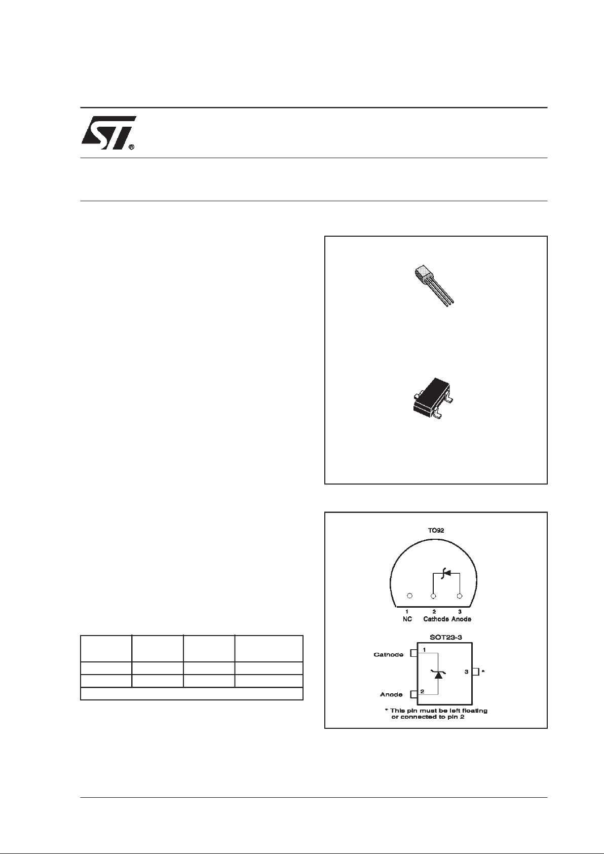
PIN CONNECTIONS (top view)
Precision TO92 SOT23-3
SOT23
Marking
2% TS822IZ TS822IL L223
1% TS822AIZ TS822AIL L222
Single temperature range: -40 to +85°C
Z
TO-92
(Plastic Package)
L
SOT23-3L
(Plastic Micropackage)
TS822
2.5V MICROPOWER SHUNT VOLTAGE REFERENCE
March 2000

TS822
2/8
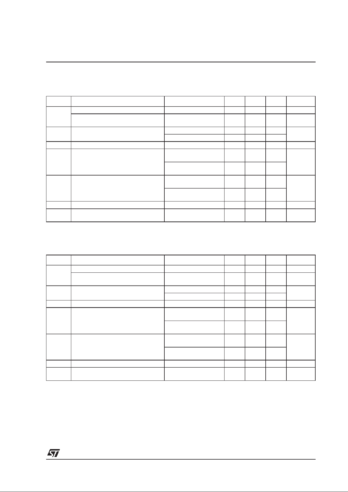
ABSOLUTE MAXIMUM RATINGS
OPERATING CONDITIONS
Symbol Parameter Value Unit
I
k
Reverse Breakdown Current 20 mA
I
f
Forward Current 10 mA
P
d
Power Dissipation
1)
SOT23-3
TO-92
360
625
mW
T
oper
Operating Free Air Temperature Range -40 to +85 °C
T
std
Storage Temperature -65 to +150 °C
ESD Human Body Model (HBM) 2 kV
Machine Model (MM) 200 V
T
lead
Lead Temperature (soldering, 10 seconds) 260 °C
1. Pd has been calculated with Tamb = 25°C and Rthja = 200°C/W for the TO92 package
Rthja = 340°C/W for the STO23-3L package
Symbol Parameter Value Unit
I
kmin
Minimum Operating Current 50 µA
I
kmax
Maximum Operating Current 15 mA
TS822
3/8
ELECTRICAL CHARACTERISTICS
TS822 (2% Precision)
Tamb = 25°C (unless otherwise specified)
ELECTRICAL CHARACTERISTICS
TS822A (1% Precision)
Tamb = 25°C (unless otherwise specified)
Note : Limits are 100% production tested at 25°C. Limits over temperature are guaranteed through correlation and by design.
Symbol Parameter Test Condition Min. Typ. Max. Unit
Vk
Reverse Breakdown Voltage Ik = 100µA 2.45 2.5 2.55 V
Reverse Breakdown Voltage Tolerange
Ik = 100µA
-40°C < T < +85°C
-50
-66
50
66
mV
Ikmin Minimum Operating Current
T=25°C4050
µA
-40°C < T < +85°C60
∆Vref/∆T Average Temperature Coefficient Ik = 100µA 30 100 ppm/°C
∆Vk/∆Ik
Reverse Breakdown Voltage Change
with Operating Current Range
Ikmin < Ik < 1mA
-40°C < T < +85°C
0.4 1
1.2
mV
1mA < Ik < 15mA
-40°C < T < +85°C
2.5 8
10
Rka Reverse Static Impedance
Ik = Ikmin to 1mA
-40°C < T < +85°C
0.4 1
1.2
Ω
Ik = 1 to 15mA
-40°C < T < +85°C
0.2 0.6
0.7
Kvh Long Term Stability Ik = 100µA, t = 1000hrs 120 ppm
En Wide Band Noise
Ik = 100µA
10Hz < f < 10kHz
35 µVrms
Note : Limits are 100% production tested at 25°C. Limits over temperature are guaranteed through correlation and by design.
Symbol Parameter Test Condition Min. Typ. Max. Unit
Vk
Reverse Breakdown Voltage Ik = 100µA 2.475 2.5 2.525 V
Reverse Breakdown Voltage Tolerange
Ik = 100µA
-40°C < T < +85°C
-25
-41
25
41
mV
Ikmin Minimum Operating Current
T=25°C4050
µA
-40°C < T < +85°C60
∆Vref/∆T Average Temperature Coefficient Ik = 100µA 30 100 ppm/°C
∆Vk/∆Ik
Reverse Breakdown Voltage Change
with Operating Current Range
Ikmin < Ik < 1mA
-40°C < T < +85°C
0.4
1
1.2
mV
1mA < Ik < 15mA
-40°C < T < +85°C
2.5 8
10
Rka Reverse Static Impedance
Ik = Ikmin to 1mA
-40°C < T < +85°C
0.4 1
1.2
Ω
Ik = 1mA to 15mA
-40°C < T < +85°C
0.2 0.6
0.7
Kvh Long Term Stability Ik = 100µA, t = 1000hrs 120 ppm
En Wide Band Noise
Ik = 100µA
10Hz < f < 10kHz
35 µVrms
 Loading...