

SGS Thomson Microelectronics TPN3021 Datasheet
TPN3021
ApplicationSpecific Discretes
A.S.D.
FEATURES
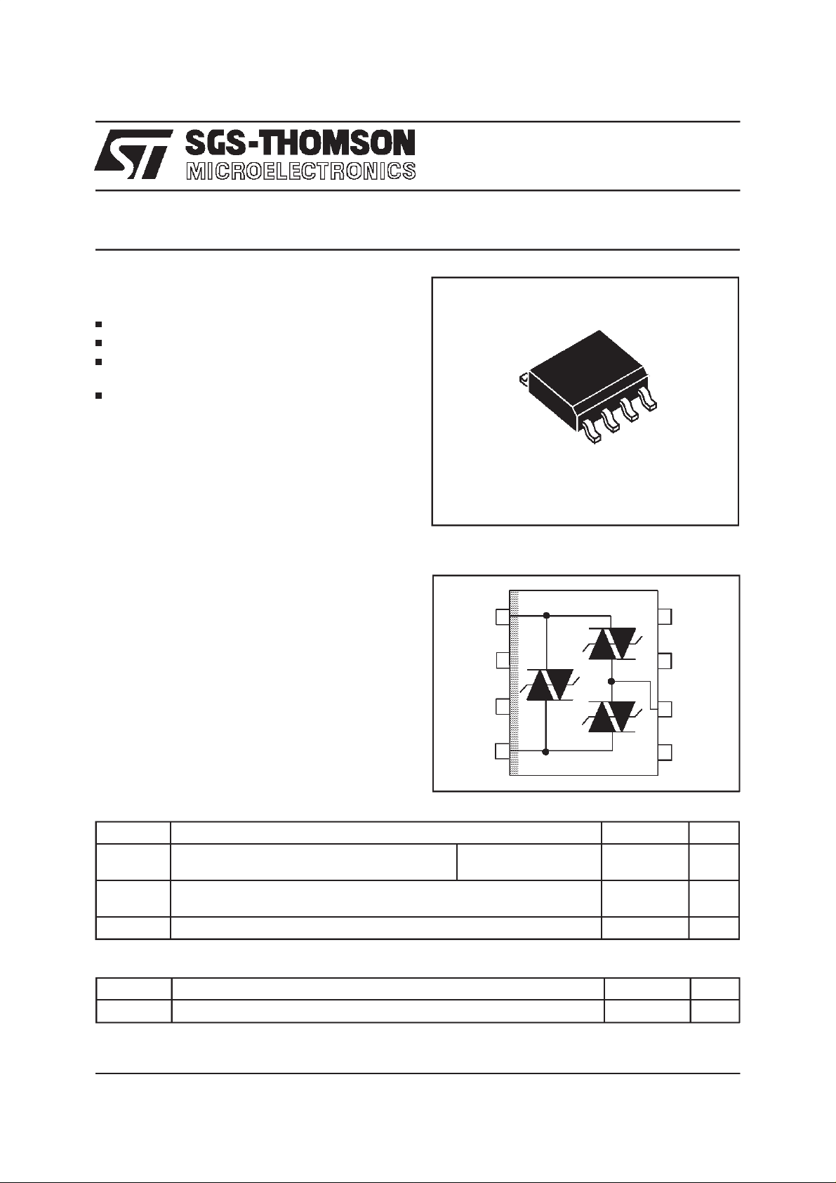
TRIPLECROWBARPROTECTION
PEAKPULSECURRENT:I
VERYLOW CAPACITANCE:
C = 30 pF
PROTECTS HIGH-SPEED LINE DRIVERS /
RECEIVERS
DESCRIPTION
Dedicated to dataline protection, this device
provides a triple protection function. It ensures
the same protection capability with the same
breakdown voltage both in common mode and
in differential mode.
Witha stand-off voltage of 28Vand a very low capacitance,thisdevice isable to protecthigh-speed
interfacessuchas T1/E1interface.
=30A,10/1000µs
PP
TRIPOLAR OVERVOLTAGE PROTEC-
TION FOR NETWORK INTERFACES
SO8
SCHEMATICDIAGRAM
I/O
1
1
NC
8
COMPLIESWITHTHEFOLLOW INGSTANDAR DS:
NC
NC
2
7
- IEC801-2 15kV (airdischarge)
- IEC801-4 40A (repetitive2.5kHz)
- IEC801-5 1.2/50µs 4kV
8/20µs 100A
ABSOLUTEMAXIMUMRATINGS (T
amb
=25°C)
NC
I/O
3
4
2
GND
6
NC
5
Symbol Parameter Value Unit
I
pp
Peakpulsecurrent 10/1000µs
8/20 µs
T
stg
Tj
T
L
Storagetemperaturerange
Maximumjunctiontemperature
Maximumleadtemperaturefor solderingduring 10s 260 °C
30
150
- 40 to + 150
150
THERMAL RESISTANCE
Symbol Parameter Value Unit
R
th(j-a)
TM: ASD is a trademark of SGS-THOMSON Microelectronics.
February 1998 - Ed : 2
Junctionto ambient 170 °C/W
A
A
°C
°C
1/4
TPN3021
ELECTRICALCHARACTERISTICS
Symbol Parameter
V
RM
V
BO
V
BR
I
H
I
BO
I
RM
I
PP
Stand-offvoltage
Breakovervoltage
Breakdownvoltage
Holdingcurrent
Breakovercurrent
Leakagecurrentat V
Peak pulsecurrent
C Capacitance
αT Temperaturecoefficient
Type I
RM
@V
RM
max.
note1
µAV VmAmApFpF10
(T
RM
amb
=25°C)
V
BO@IBO
max.
I
H
min.
note2
I
I
PP
I
BO
I
H
I
RM
C
typ. max.
note3
V
RM BO
αT
typ.
note 4
-4
V
V
/°C
TPN3021 4 28 38 100 30 25 30 8
Note 1 :
Between any I/Opin and Ground or between I/O1and I/O2.
Note 2 :
See the functional holding current (IH) test circuit.
Note 3 :
Between any I/Opin and GNDor betweenI/O1and I/O2at 0V bias, V
Note 4 :
∆VBO= αTx(T
-25) x VBO(25°C).
amb
=30 mV, F = 1 MHz.
RMS
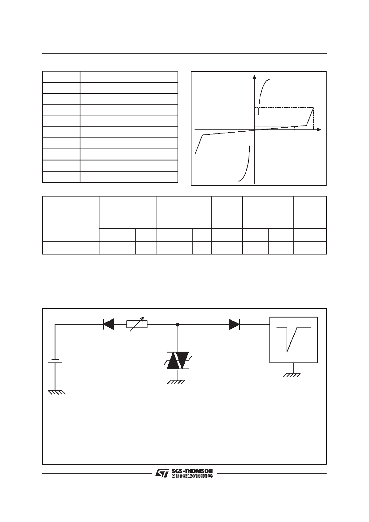
FUNCTIONAL HOLDINGCURRENT (IH) TEST CIRCUIT : GO-NOGO TEST
R
-V
P
D.U.T
V
BAT
=
-
48 V
Thisis a GO-NOGO test which allowsto confirmthe holding current(IH)levelin a functionaltest circuit.
Surge generator
TESTPROCEDURE :
- Adjust the current level at the I
- Fire the D.U.T.with a surgecurrent : I
valueby short circuitingthe D.U.T.
H
= 10A,10/1000µs.
pp
- The D.U.T.will comeback to theoff-state within a durationof 50ms max.
2/4
 Loading...