

SGS Thomson Microelectronics TPI12011N, TPI8011N Datasheet
TPI8011N
ApplicationSpecific Discretes
A.S.D.
FEATURES
BIDIRECTIONALTRIPLE CROWBAR
PROTECTION.
PEAKPULSECURRENT:
I
=30A , 10/1000 µs.
PP
BREAKDOWN VOLTAGE:
TPI80xxN: 80V
TPI120xxN: 120V.
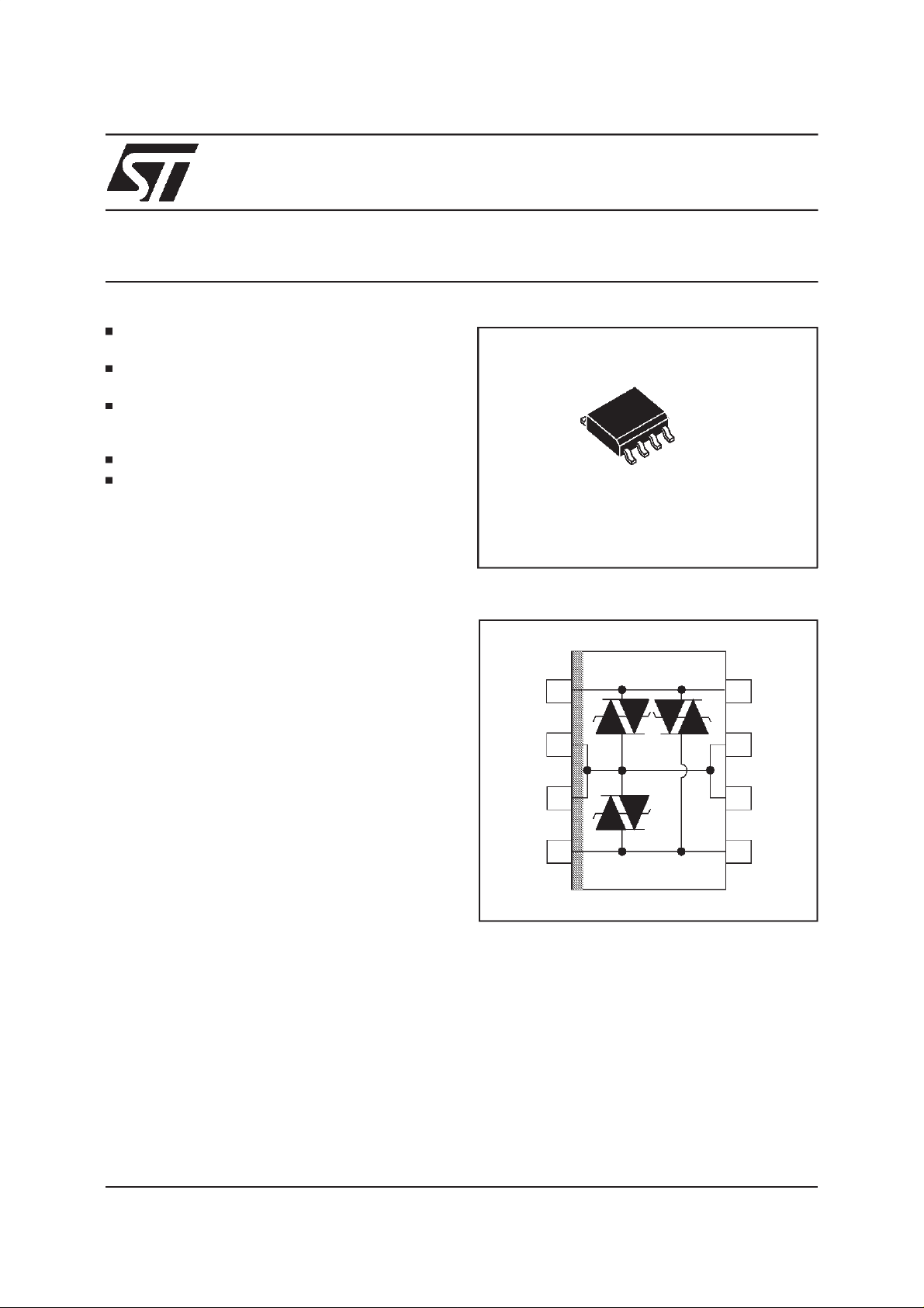
AVAILABLEIN SO8 PACKAGES.
LOWDYNAMICBREAKOVER VOLTAGE:
TPI80N: 150V
TPI120:200V
DESCRIPTION
Dedicateddevices forISDNinterfaceand high
speeddatatelecomline protection.Equivalentto
a triple TRISILwithlow capacitance.
Thesedevices provide:
low capacitance from lines to ground, allowing
-
high speed transmission without signal
attenuation.
- good capacitance balance between lines in
ordertoensurelongitudinalbalance.
- fixed breakdown voltage in both common and
differentialmodes.
- the same surge current capability in both
commonand differentialmodes.
A particular attention has been given to the
-
internalwirebonding.The”4-point”configuration
ensures a reliable protection, eliminating
overvoltages introduced by the parasitic
inductances of the wiring (Ldi/dt), especially for
veryfasttransientovervoltages.
TPI12011N
TRIPOLAR PROTECTION
FOR ISDN INTERFACES
SO8
SCHEMATIC DIAGRAM
Tip
GND
GND
Ring
1
2
3
4
8
Tip
GND
7
GND
6
5
Ring
COMPLIESWITHTHEFOLLOWINGSTANDARDS:
CCITTK17 -K20 10/700 µs 1.5 kV
5/310µs38A
VDE0433 10/700 µs2kV
5/310µs50A
VDE0878 1.2/50µs 1.5 kV
1/20 µs40A
CNET 0.5/700µs 1.5 kV
0.2/310µs38A
TM: ASD is atrademark of SGS-THOMSONMicroelectronics.
November 1999 Ed : 3A
1/7
TPI8011N/TPI12011N
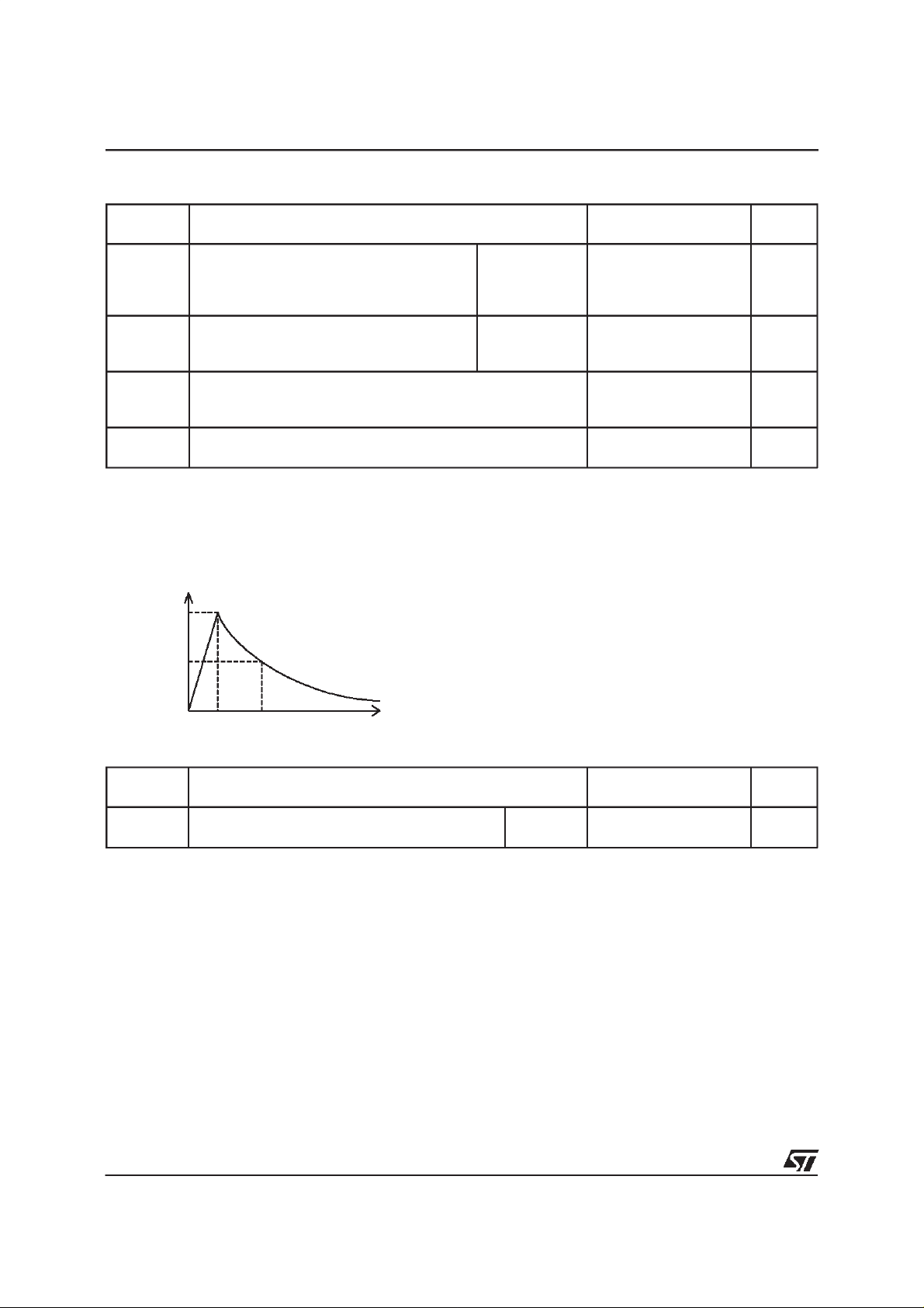
ABSOLUTE MAXIMUM RATINGS(T
amb
=25°C)
Symbol Parameter Value Unit
I
I
TSM
PP
Peak pulsecurrent (seenote 1)
Non repetitivesurge peak on-state
current (F = 50 Hz).
T
stg
T
j
T
L Maximumleadtemperaturefor solderingduring10s
Note 1 :
Storagetemperaturerange
Maximumjunctiontemperature
Pulse waveform :
10/1000µst
5/310µst
2/10µst
%I
PP
100
=10µst
r
=5µst
r
=2µst
r
=1000µs
p
=310µs
p
=10µs
p
10/1000µs
5/320µs
2/10 µs
tp= 10ms
t=1s
30
40
90
8
3.5
- 55 to + 150
150
260 °C
A
A
°C
50
0
t
t
rp
t
THERMAL RESISTANCES
Symbol Parameter Value Unit
R
th (j-a) Junctionto ambient
SO8 170
°
C/W
2/7
TPI8011N/TPI12011N
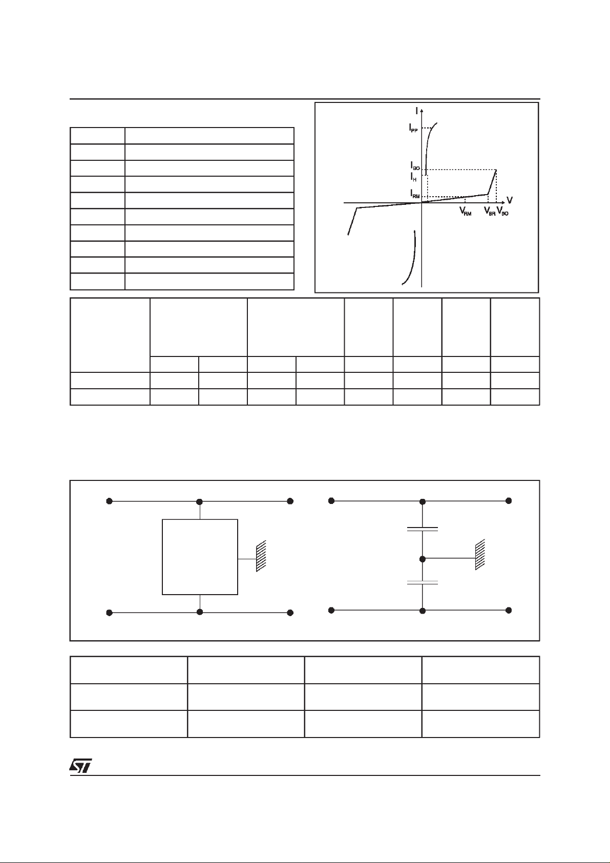
ELECTRICALCHARACTERISTICS
Symbol Parameter
V
RM Stand-offvoltage
I
RM Leakagecurrent
V
BR
V
BO
I
H
I
BO Breakovercurrent
I
PP Peakpulsecurrent
V
F ForwardVoltageDrop
C
Types
Breakdownvoltage
Breakovervoltage
Holdingcurrent
Capacitance
@V
I
RM
RM
max. min. max. typ. max. min.
µAV VmAV VmAmA
TPI8011N
TPI12011N
10 70 80 1 120 150 800 150
10 105 120 1 180 200 800 150
(
Tamb
=25°C)
VBR@I
R
V
BO
VBO
dyn.
I
BO
I
H
note1 note2 note1 note3
Note 1: Seethe reference testcircuit 1.
Note 2: Surgetest according toCCITT 1.5kV,10/700 µs betweenTip or Ringand ground.
Note 3: Seefunctional holding currenttest circuit2.
CAPACITANCES CHARACTERISTICS
LINE A
LINE A
TPIxx
LINE B
CONFIGURATION
=1V
V
A
=56V
V
B
V
=56V
A
=1V
V
B
(pF)
C
A
max
70 50 30
50 70 30
LINE B
CB(pF)
max
C
A
C
B
CA-CB(pF)
max
3/7
 Loading...