

SGS Thomson Microelectronics TPA270, TPA220, TPA240, TPA200, TPA68 Datasheet
...
FEATURES
BIDIRECTIONALCROWBARPROTECTION.
VOLTAGERANGE:FROM 62 V TO270 V.
HOLDINGCURRENT:
=150mAmin.
I
H
REPETITIVEPEAKPULSECURRENT :
I
= 50 A, 10/1000 µs.
PP
TPA SERIES
TRISIL
F126
DESCRIPTION
The TPA seriesare TRISIL devices especiallydesigned for protecting sensitive telecommunication
equipmentagainstlightning and transientvoltages
induced by AC power lines. They are available in
theF126 axial package.
TRISIL devices provide bidirectional protection
by crowbar action. Their characteristic response
to transientovervoltagesmakesthem particularly
suited to protect voltage sensitive telecommunication equipment.
COMPLIESWITH THE
FOLLOWINGSTANDARDS:
(CCITT)ITU-K20 1000 10/700 5/310 25 (CCITT)ITU-K17 1500 10/700 5/310 38 VDE0433 2000 10/700 5/310 50 VDE0878
IEC-1000-4-5
FCCPart 68, lightningsurge
type A
FCCPart 68, lightningsurge
type B
BELLCORETR-NWT-001089
Firstlevel
BELLCORETR-NWT-001089
Secondlevel
CNETl31-24 1000 0.5/700 0.8/310 25 -
PeakSurge
Voltage
(V)
2000 1.2/50 1/20 50 -
level3
level4
1500
800
1000 9/720 5/320 25 -
2500
1000
5000 2/10 2/10 150 11.5
SCHEMATIC DIAGRAM
Voltage
Waveform
(µs)
10/700
1.2/50
10/160
10/560
2/10
10/1000
Current
Waveform
5/310
10/160
10/560
10/1000
(µs)
8/20
2/10
Admissible
Ipp
(A)
50
100
75
55
150
50
Necessary
Resistor
(Ω)
-
-
12.5
6.5
11.5
10
October 1998- Ed: 9A
1/5
TPA SERIES
ABSOLUTEMAXIMUMRATINGS(T
Symbol Parameter Value Unit
P Powerdissipationon infinite heatsink T
I
PP
I
TSM
2
tI
I
Peakpulse current 10/1000µs
Nonrepetitivesurgepeak on-statecurrent tp = 20 ms 30 A
2
t value for fusing tp = 20 ms 9 A2s
dV/dt Critical rate of riseof off-statevoltage V
T
stg
T
j
T
L
Storagetemperaturerange
Maximumjunction temperature
Maxi m umleadtemperatureforsolderingduring10sat5mmfromcase
THERMALRESISTANCES
Symbol Parameter Value Unit
(j-l) Junctionto leads(L
R
th
(j-a)
R
th
Junctionto ambient on printed circuit(L
lead
ELECTRICALCHARACTERISTICS
(T
=25°C)
amb
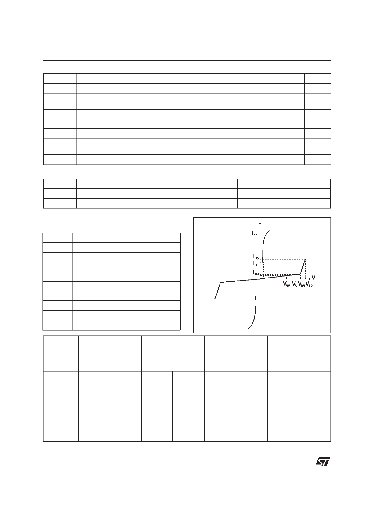
Symbol Parameter
V
RM
I
RM
V
V
BR
V
BO
I
H
I
BO
I
PP
C
Stand-offvoltage
Leakagecurrent at stand-offvoltage
ContinuousReversevoltage
R
Breakdownvoltage
Breakovervoltage
Holdingcurrent
Breakovercurrent
Peak pulse current
Capacitance
=25°C)
amb
C 1.7 W
=50
amb
°
8/20µs
RM
- 55to +150
= 10mm) 60
lead
= 10 mm)
100
50
100
5 kV/µs
150
230 °C
°C
°C
C/W
°
C/W
°
A
Type IRM@V
RM
IR@V
R
max. max.
note 1
AV
µ
TPA62
TPA68
TPA100
TPA120
TPA130
TPA180
TPA200
TPA220
TPA240
TPA270
Note 1: IRmeasured at VRguarantee V
Note 3: See test circuit 2. Note 4: V
2/5
2
2
2
2
2
2
2
2
2
2
56
61
90
108
117
162
180
198
216
243
BRmin
AV VmAmApF
µ
≥ V
50
50
50
50
50
50
50
50
50
50
R
62
68
100
120
130
180
200
220
240
270
Note 2: Measured at 50 Hz (1 cycle) - See test circuit 1.
VBO@I
BO
max.
note 2
82
90
133
160
173
240
267
293
320
360
= 1V, F = 1MHz. Refer tofig.3 for C versus VR.
R
800
800
800
800
800
800
800
800
800
800
I
H
min.
note3
150
150
150
150
150
150
150
150
150
150
C
max.
note 4
150
150
100
100
100
100
100
100
100
100
 Loading...