

SGS Thomson Microelectronics TDA9109-N Datasheet
TDA9109/N
LOW-COST DEFLECTIONPROCESSOR
FOR MULTISYNC MONITORS
June 1998
SHRINK32
(Plastic Package)
ORDER CODE : TDA9109/N
HORIZONTAL
.
SELF-ADAPTATIVE
.
DUALPLLCONCEPT
.
150kHzMAXIMUM FREQUENCY
.
X-RAYPROTECTIONINPUT
.
I2C CONTROLS : H-POSITION, FREQUENCY
GENERATORFOR BURN-IN MODE
VERTICAL
.
VERTICALRAMP GENERATOR
.
50 TO165Hz AGC LOOP
.
GEOMETRYTRACKINGWITHVPOS& VAMP
.
I2C CONTROLS:
VAMP, VPOS, S-CORR, C-CORR
.
DC BREATHING COMPENSATION
I
2
C GEOMETRYCORRECTIONS
.
VERTICALPARABOLAGENERATOR
(Pincushion,Keystone)
.
HORIZONTALDYNAMICPHASE
(SidePin Balance& Parallelogram)
.
HORIZONTALAND VERTICALDYNAMIC FOCUS (Horizontal Focus Amplitude, Horizontal
FocusSymmetry,VerticalFocus Amplitude)
GENERAL
.
SYNCPROCESSOR
.
12V SUPPLYVOLTAGE
.
8V REFERENCEVOLTAGE
.
HOR.& VERT. LOCK/UNLOCK OUTPUTS
.
READ/WRITEI2C INTERFACE
.
VERTICALMOIRE
.
B+REGULATOR
- INTERNAL PWM GENERATOR FOR B+
CURRENT MODE STEP-UP CONVERTER
- S WITCHABL E TO STEP-DOWN CONVERTER
-I
2
CADJUSTABLEB+REFERENCE VOLTAGE
- OUTPUT PULSES SYNCHRONIZED ON
HORIZONTALFREQUENCY
- INTERNALMAX. CURRENT LIMITATION
.
COMPARED WITH THE TDA9109,
THE TDA9109/NHAS:
-NOI
2
C FREE RUNNING FREQUENCY AD-
JUSTMENT
- FIXED HORIZONTALDUTY CYCLE (48%)
- INCREASEDMAX.STORAGETIME OF THE
HORIZONTALSCANNING TRANSISTOR
DESCRIPTION
The TDA9109/N is a monolithic integrated circuit
assembledin32-pinshrinkdual in lineplasticpackage.ThisIC controlsall thefunctionsrelatedtothe
horizontal and vertical deflection in multimode or
multi-frequencycomputerdisplaymonitors.
The internal sync processor, combined with the
very powerful geometrycorrection block makethe
TDA9109/N suitable for very high performance
monitors,using very few externalcomponents.
Thehorizontaljitter levelisverylow.Itisparticularly
well suited forhigh-end 15” and 17” monitors.
Combined with the ST7275Microcontroller family,
TDA9206 (Video preamplifier) and STV942x (OnScreen Display controller) the TDA9109/N allows
fullyI
2
Cbus controlled computer display monitors
to be built with a reduced number of external
components.
1/32

1
2
3
4
5
6
7
8
9
10
11
12
13
14
15
16
22
23
24
25
26
21
20
19
18
17
5V
SDA
SCL
V
CC
GND
HOUT
XRAY
EWOUT
VOUT
VCAP
V
REF
VAGCCAP
VGND
BREATH
B+GNDI
SENSE
REGIN
COMP
HREF
HFLY
HGND
FOCUS-OUT
HFOCUSCAP
HPOSITION
PLL1F
R0
C0
PLL2C
HLOCKOUT
H/HVIN
VSYNCIN
32
31
30
29
28
27
BOUT
9109N-01.EPS
PIN CONNECTIONS
TDA9109/N
2/32
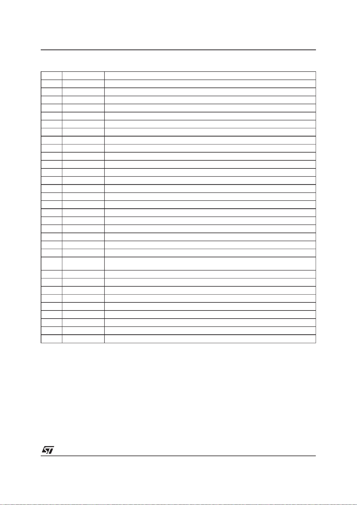
PIN CONNECTIONS
Pin Name Function
1 H/HVIN TTL compatible Horizontal sync Input (separate or composite)
2 VSYNCIN TTL compatible Vertical sync Input (for separated H&V)
3 HLOCKOUT First PLL Lock/Unlock Output (0V unlocked - 5V locked)
4 PLL2C Second PLL LoopFilter
5 C0 Horizontal Oscillator Capacitor
6 R0 Horizontal Oscillator Resistor
7 PLL1F First PLL Loop Filter
8 HPOSITION HorizontalPosition Filter (capacitor to be connected to HGND)
9 HFOCUSCAP Horizontal Dynamic Focus Oscillator Capacitor
10 FOCUSOUT Mixed Horizontal and Vertical Dynamic Focus Output
11 HGND Horizontal Section Ground
12 HFLY Horizontal Flyback Input (positivepolarity)
13 HREF Horizontal Section ReferenceVoltage (to be filtered)
14 COMP B+ Error Amplifier Output for frequency compensation and gain setting
15 REGIN Regulation Input of B+ control loop
16 I
SENSE
Sensing ofexternal B+ switching transistor current, or switch for step-down converter
17 B+GND Ground (related toB+ reference adjustment)
18 BREATH DC Breathing Input Control (compensation of vertical amplitude against EHV variation)
19 VGND Vertical Section Ground
20 VAGCCAP Memory Capacitor for Automatic Gain Control Loop in Vertical Ramp Generator
21 V
REF
Vertical Section Reference Voltage (to be filtered)
22 VCAP Vertical Sawtooth Generator Capacitor
23 VOUT Vertical Ramp Output(withfrequencyindependantamplitude and S or C Correctionsif any).
It is mixed with vertical position voltage and vertical moiré.
24 EWOUT Pin Cushion - E/W Correction Parabola Output
26 HOUT Horizontal Drive Output (internal transistor, open collector)
25 XRAY X-RAY protection input (with internal latch function)
27 GND General Ground (referenced to V
CC
)
28 BOUT B+ PWMRegulator Output
29 V
CC
Supply Voltage (12V typ)
30 SCL I
2
C Clock Input
31 SDA I
2
C Data Input
32 5V Supply Voltage (5V typ.)
9109N-01.TBL
TDA9109/N
3/32
QUICK REFERENCE DATA
Parameter Value Unit
Horizontal Frequency 15 to 150 kHz
Autosynch Frequency (for given R0 and C0) 1 to 4.5 f0
æ Horizontal Sync Polarity Input YES
Polarity Detection (on bothHorizontal and Vertical Sections) YES
TTL Composite Sync YES
Lock/Unlock Identification (on both Horizontal 1st PLL and Vertical Section) YES
I
2
C Control for H-Position
±
10 %
XRAY Protection YES
Fixed I
2
C Horizontal Duty Cycle 48 %
I
2
C Free Running Frequency Adjustment NO
Stand-by Function YES
Dual Polarity H-Drive Outputs NO
Supply Voltage Monitoring YES
PLL1 Inhibition Possibility NO
Blanking Outputs NO
Vertical Frequency 35 to 200 Hz
Vertical Autosync (for 150nF on Pin 22 and 470nF on Pin 20) 50 to 165 Hz
Vertical S-Correction YES
Vertical C-Correction YES
Vertical Amplitude Adjustment YES
DC Breathing Control on VerticalAmplitude YES
Vertical Position Adjustment YES
East/West (E/W) Parabola Output (also known as Pin Cushion Output) YES
E/W Correction Amplitude Adjustment YES
Keystone Adjustment YES
Internal Dynamic Horizontal Phase Control YES
Side Pin Balance Amplitude Adjustment YES
Parallelogram Adjustment YES
Tracking of Geometric Corrections with Vertical Amplitude and Position YES
Reference Voltage (both on Horizontal and Vertical) YES
Dynamic Focus (both Horizontal and Vertical) YES
I
2
C Horizontal Dynamic Focus Amplitude Adjustment YES
I
2
C Horizontal Dynamic Focus Symmetry Adjustment YES
I
2
C Vertical Dynamic Focus Amplitude Adjustment YES
Detection of Input Sync Type (biased from 5V alone) YES
Vertical Moiré Output YES
I
2
C Controlled V-Moiré Amplitude YES
Frequency Generator for Burn-in YES
Fast I
2
C Read/Write 400 kHz
B+ Regulation adjustable by I
2
C YES
9109N-02.TBL
TDA9109/N
4/32
V
REF
4
131211
5
9
3
1
67 26
2
Amp & Symmetry
2 x 5 bits
HFOCUSCAP
HREF
HGND
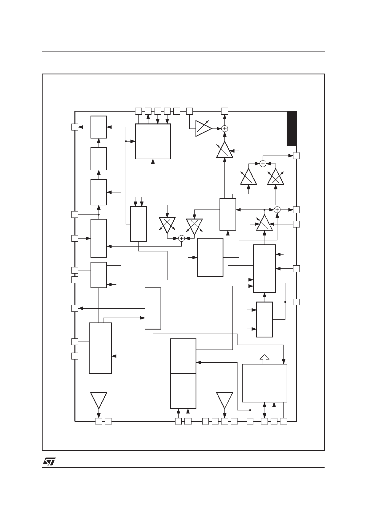
SYNC
PROCESSOR
SYNC INPUT
SELECT
(1 bit)
B+
CONTROLLER
LOCK/UNLOCK
IDENTIFICATION
PHASE
COMPARATOR
PHASE
SHIFTER
H-DUTY
(48%)
HOUT
BUFFER
VCO
Forced
Frequency
2 bits
VAMP
7 bits
21
22 23
30
192432
31
27
V
REF
VGND
5V
SDA
SCL
GND
V
REF
S AND C
CORRECTION
VERTICAL
OSCILLATOR
RAMP GENERATOR
GEOMETRY
TRACKING
6 bits 6 bits
Keyst.
6 bits
E/W
7 bits
TDA9109/N
PLL1F
HLOCKOUT
HPOSITION
R0
C0
HFLY
PLL2C
HOUT
V
CAP
V
AGCCAP
V
OUT
VSYNCIN
H/HVIN
EWOUT
X
2
X
2
X
25
29
XRAY
V
CC
RESET
GENERATOR
I
2
C INTERFACE
VPOS
7 bits
20
VAMPVDF
6 bits
10 FOCUS
Parallelogram
6 bits
Spin Bal
6 bits
X
2
X
2
VSYNC
SAFETY
PROCESSOR
XRAY
V
CC
17
BGND
16
I
SENSE
15 REGIN
28 B+OUT
14 COMP
B+ Adjust
7 bits
18
BREATH
PHASE/FREQUENCY
COMPARATOR
H-PHASE(7 bits)
8
VERTICAL
MOIRE
CANCEL
5 BITS+ON/OFF
9109N-02.EPS
BLOCKDIAGRAM
TDA9109/N
5/32

ABSOLUTE MAXIMUMRATINGS
Symbol Parameter Value Unit
V
CC
Supply Voltage (Pin 29) 13.5 V
V
DD
Supply Voltage (Pin 32) 5.7 V
V
IN
Max Voltage on Pin 4
Pin 9
Pin 5
Pins 6, 7, 8, 14, 15, 16, 20, 22
Pin 10, 18, 23, 24, 25, 26,28
Pins 1, 2, 3, 30, 31
4.0
5.5
6.4
8.0
V
CC
V
DD
V
V
V
V
V
V
VESD
ESD susceptibility Human Body Model,100pF Dischargethrough 1.5kΩ
EIAJ Norm,200pF Discharge through 0Ω
2
300
kV
V
T
stg
Storage Temperature -40, +150
o
C
T
j
Junction Temperature +150
o
C
T
oper
Operating Temperature 0, +70
o
C
9109N-03.TBL
THERMAL DATA
Symbol Parameter Value Unit
R
th (j-a)
Junction-Ambient Thermal Resistance Max. 65
o
C/W
9109N-04.TBL
SYNC PROCESSOR
OperatingConditions (V
DD
=5V,T
amb
=25oC)
Symbol Parameter Test Conditions Min. Typ. Max. Unit
HsVR Voltage on H/HVIN Input Pin 1 0 5 V
MinD Minimum Horizontal Input Pulses Duration Pin 1 0.7 µs
Mduty Maximum Horizontal Input Signal Duty Cycle Pin 1 25 %
VsVR Voltage on VSYNCIN Pin2 0 5 V
VSW Minimum Vertical Sync Pulse Width Pin 2 5 µs
VSmD Maximum Vertical SyncInput Duty Cycle Pin 2 15 %
VextM Maximum Vertical Sync Widthon TTLH/Vcomposite Pin 1 750
µ
s
I
HLOCKOUT
Sink and Source Current Pin3 250 µA
ElectricalCharacteristics(VDD=5V,T
amb
=25oC)
Symbol Parameter Test Conditions Min. Typ. Max. Unit
VINTH Horizontal and Vertical Input Logic Level
(Pins 1, 2)
Low Level
High Level 2.2
0.8 V
V
RIN Horizontal and Vertical Pull-Up Resistor Pins 1, 2 200 k
Ω
TfrOut Fall and Rise Time, Output CMOS Buffer Pin 3, C
OUT
= 20pF 200 ns
VHlock Horizontal1st PLLLock OutputStatus (Pin 3) Locked, I
LOCKOUT
= -250µA
Unlocked, I
LOCKOUT
= +250µA 4.405
0.5 V
V
VoutT Extracted Vsync Integration Time (% of T
H
)
on H/V Composite (see Note 1)
C0 = 820pF 26 35 %
Note 1 : THisthe horizontal period.
I2C READ/WRITE (see Note 2)
ElectricalCharacteristics(V
DD
=5V,T
amb
=25oC)
Symbol Parameter Test Conditions Min. Typ. Max. Unit
I
2
C PROCESSOR
Fscl Maximum Clock Frequency Pin 30 400 kHz
Tlow Low period of the SCLClock Pin30 1.3
µ
s
Thigh High period of the SCL Clock Pin30 0.6
µ
s
Vinth SDA and SCL Input Threshold Pins 30,31 2.2 V
VACK Acknowledge Output Voltage on SDA input with 3mA Pin 31 0.4 V
Note 2 : See also I2C Table Control and I2C Sub Address Control.
9109N-05.TBL
TDA9109/N
6/32
HORIZONTAL SECTION
OperatingConditions
Symbol Parameter Test Conditions Min. Typ. Max. Unit
VCO
R
0(Min.)
Minimum Oscillator Resistor Pin 6 6 k
Ω
C
0(Min.)
Minimum Oscillator Capacitor Pin 5 390 pF
F
(Max.)
Maximum Oscillator Frequency 150 kHz
OUTPUT SECTION
I12m Maximum Input Peak Current Pin 12 5 mA
HOI Horizontal Drive Output Maximum Current Pin 26, Sunk current 30 mA
ElectricalCharacteristics(VCC=12V,T
amb
=25oC)
Symbol Parameter Test Conditions Min. Typ. Max. Unit
SUPPLY AND REFERENCE VOLTAGES
V
CC
Supply Voltage Pin 29 10.8 12 13.2 V
V
DD
Supply Voltage Pin 32 4.5 5 5.5 V
I
CC
Supply Current Pin 29 50 mA
I
DD
Supply Current Pin 32 5 mA
V
REF-H
Horizontal Reference Voltage Pin 13, I = -2mA 7.4 8 8.6 V
V
REF-V
Vertical Reference Voltage Pin 21, I = -2mA 7.4 8 8.6 V
I
REF-H
Max. Sourced Current on V
REF-H
Pin 13 5 mA
I
REF-V
Max. Sourced Current on V
REF-V
Pin 21 5 mA
1st PLL SECTION
HpolT Delay Time for detecting polarity change
(see Note 3)
Pin 1 0.75 ms
V
VCO
VCO Control Voltage (Pin 7) V
REF-H
=8V f
0
fH(Max.)
1.3
6.2
V
V
Vcog VCO Gain (Pin 7) R
0
= 6.49kΩ,C0= 820pF,
dF/dV = 1/11R
0C0
17.1 kHz/V
Hph Horizontal Phase Adjustment(see Note 4) % of Horizontal Period ±10 %
Vbmin
Vbtyp
Vbmax
HorizontalPhaseSetting Value (Pin8) (seeNote4)
Minimum Value
Typical Value
Maximum Value
Sub-Address 01
Byte x1111111
Byte x1000000
Byte x0000000
2.8
3.4
4.0
V
V
V
IPll1U
IPll1L
PLL1 Filter Current Charge PLL1is Unlocked
PLL1 is Locked
±140
±1
µA
mA
f
0
Free Running Frequency R0= 6.49kΩ,C0= 820pF,
f
0
= 0.97/8R0C
0
22.8 kHz
df0/dT Free RunningFrequency Thermal Drift
(No drift on external components) (see Note 5)
-150 ppm/C
CR PLL1 Capture Range (see Note 6) R
0
= 6.49kΩ,C0= 820pF,
from f
0
+0.5kHz to 4.5f
0
fH(Min.)
f
H
(Max.) 90
25 kHz
kHz
FF Forced Frequency FF1 Byte 11xxxxxx
FF2 Byte 10xxxxxx
Sub-Address 02 2f0
3f0
Notes: 3. This delay is mandatory to avoid a wrong detection of polarity change in the case of a composite sync.
4. See Figure 10 for explanation of referencephase.
5. These parameters are not tested on each unit. They are measured during our internal qualification.
6. This PLL capturerange may be obtained only if f0is adjusted (for instanceby adjusting R0) . If not, more marginmust be provided
between f
H
(Min.) and f0, to cope withthe components spread.
9109N-05.TBL
TDA9109/N
7/32
HORIZONTAL SECTION (continued)
ElectricalCharacteristics(V
CC
=12V,T
amb
=25oC) (continued)
Symbol Parameter Test Conditions Min. Typ. Max. Unit
2nd PLL SECTION AND HORIZONTAL OUTPUT SECTION
FBth Flyback Input Threshold Voltage (Pin 12) 0.65 0.75 V
Hjit Horizontal Jitter At 31.4kHz 70 ppm
HD Horizontal Drive OutputDuty-Cycle Pin 26, see Note 7 48 %
XRAYth X-RAY Protection Input ThresholdVoltage Pin 25, see Note 8 8 V
Vphi2 Internal Clamping Levels on 2nd PLL
Loop Filter (Pin 4)
Low Level
High Level
1.6
4.0
V
V
VSCinh Threshold Voltage to Stop H-Out,V-Out,
B-Out and Reset XRAY
when V
CC
< VSCinh (see Note 8)
Pin 29 7.5 V
HDvd Horizontal Drive Output (low level) Pin 26, I
OUT
= 30mA 0.4 V
HORIZONTAL DYNAMIC FOCUS FUNCTION
HDFst HorizontalDynamic FocusSawtooth
MinimumLevel
MaximumLevel
Pin 9, capacitor on
HFOCUSCAP and C0 = 820pF,
T
H
=20µs
2
4.7
V
V
HDFdis Horizontal Dynamic Focus Sawtooth
Discharge Width
Start by HFLY center 400 ns
HDFDC Bottom DC Output Level R
LOAD
= 10kΩ, Pin10 2 V
TDHDF DC Output VoltageThermal Drift
(see Note 5)
200 ppm/C
HDFamp Horizontal Dynamic Focus Amplitude
Min Byte xxx11111
Typ Byte xxx10000
Max Byte xxx00000
Sub-Address 03, Pin 10,
f
H
= 50kHz, Symmetry Typ. 1
1.5
3
V
PP
V
PP
V
PP
HDFKeyst Horizontal Dynamic Focus Symmetry
Min A/B Byte xxx11111
Typ Byte xxx10000
Max A/B Byte xxx00000
Sub-Address 04, f
H
= 50kHz,
Typ. Amp
B/A
A/B
A/B
223.5
1.0
3.5
VERTICAL DYNAMIC FOCUS FUNCTION (positiveparabola)
AMPVDF Vertical Dynamic Focus Parabola (added
to horizontal)Amplitude with VAMP and
VPOS Typical
Min. Byte 000000
Typ. Byte 100000
Max. Byte 111111
Sub-Address 0F
0
0.5
1
V
PP
V
PP
V
PP
VDFAMP Parabola Amplitude Function of VAMP
(tracking between VAMP and VDF) with
VPOS Typ. (see Figure 1 andNote 9)
Sub-Address 05
Byte 10000000
Byte 11000000
Byte 11111111
0.6
1
1.5
V
PP
V
PP
V
PP
VHDFKeyt Parabola Asymetry Function of VPOS
Control(tracking between VPOS andVDF)
with VAMP Max.
Sub-Address 06
Byte x0000000
Byte x1111111
0.52
0.52
V
PP
V
PP
Notes: 5. These parameters are not tested on each unit.They are measured during our internalqualification.
7. Duty Cycle is the ratio between the output transistor OFF time and the period. The power transistor is controlled OFF when the
output transistor is OFF.
8. See Figure 14.
9. S and C correction are inhibited so the output sawtooth has a linearshape.
9109N-05.TBL
TDA9109/N
8/32
VERTICALSECTION
OperatingConditions
Symbol Parameter Test Conditions Min. Typ. Max. Unit
OUTPUTS SECTION
VEWM Maximum E/W OutputVoltage Pin 24 6.5 V
VEWm Minimum E/W Output Voltage Pin 24 1.8 V
R
LOAD
Minimum Load for less than 1% VerticalAmplitude Drift Pin 20 65 M
Ω
ElectricalCharacteristics(VCC=12V,T
amb
=25oC)
Symbol Parameter Test Conditions Min. Typ. Max. Unit
VERTICAL RAMP SECTION
VRB Voltage at Ramp Bottom Point V
REF-V
= 8V, Pin 22 2 V
VRT Voltage at Ramp Top Point (with Sync) V
REF-V
= 8V, Pin 22 5 V
VRTF Voltage at Ramp Top Point (without Sync) Pin 22 VRT-0.1 V
VSTD Vertical Sawtooth Discharge Time Pin 22, C
22
= 150nF 70 µs
VFRF Vertical Free RunningFrequency
(see Note 10)
C
OSC (Pin 22)
= 150nF
Measured on Pin22
100 Hz
ASFR AUTO-SYNC Frequency (see Note 11) C
22
= 150nF ±5% 50 165 Hz
RAFD Ramp Amplitude Drift Versus Frequency at
Maximum Vertical Amplitude (see Note 5)
C
22
= 150nF
50Hz < f and f < 165Hz
200 ppm/Hz
Rlin Ramp Linearity on Pin 22 (see Note 10) 2.5V < V
27
and V27< 4.5V 0.5 %
VPOS Vertical Position Adjustment Voltage
(Pin 23 - VOUT mean value)
Sub Address 06
Byte x0000000
Byte x1000000
Byte x1111111 3.65
3.2
3.5
3.8
3.3 V
V
V
VOR Vertical Output Voltage
(peak-to-peak on Pin 23)
Sub Address 05
Byte x0000000
Byte x1000000
Byte x1111111 3.5
2.25
3
3.75
2.5 V
V
V
VOI Vertical Output Maximum Current (Pin 23) ±5mA
dVS Max Vertical S-Correction Amplitude
(see Note 12)
x0xxxxxx inhibitsS-CORR
x1111111 givesmax S-CORR
Sub Address 07
∆V/V
PP
at TV/4
∆V/V
PP
at 3TV/4
-4
+4
%
%
Ccorr Vertical C-Corr Amplitude
x0xxxxxx inhibits C-CORR
Sub Address 08
∆V/V
PP
@ TV/2
Byte x1000000
Byte x1100000
Byte x1111111
-3
0
3
%
%
%
Notes: 5. These parameters are not testedon each unit. They are measured during our internal qualification.
10. With Register 07 at Byte x0xxxxxx (S correctionis inhibited) and withRegister 08 at Bytex0xxxxxx (C correction is inhibited),the
sawtooth has a linear shape.
11. This is the frequencyrangefor which thevertical oscillatorwill automaticallysynchronize,using a single capacitorvalue on Pin22
and with a constant ramp amplitude.
12. TV is thevertical period.
9109N-05.TBL
TDA9109/N
9/32
VERTICALSECTION(continued)
ElectricalCharacteristics(V
CC
=12V,T
amb
=25oC) (continued)
Symbol Parameter Test Conditions Min. Typ. Max. Unit
East/West (E/W) FUNCTION
EW
DC
DC Output Voltage with Typ. VPOS and Keystone
inhibited
Pin 24, see Figure 2 2.5 V
TDEW
DC
DC Output Voltage Thermal Drift See Note 13 100 ppm/C
EWpara Parabola Amplitude with Max. VAMP, Typ. VPOS,
Keystone inhibited
Subaddress 0A
Byte 11111111
Byte 11000000
Byte 10000000
2.5
1.25
0
V
PP
V
PP
V
PP
EWtrack Parabola Amplitude Function of VAMP Control
(tracking between VAMPandE/W) with Typ. VPOS,
Typ. E/W Amplitude and Keystone inhibited(see
Note 10)
Subaddress 05
Byte 10000000
Byte 11000000
Byte 11111111
0.45
0.8
1.25
V
PP
V
PP
V
PP
KeyAdj Keystone Adjustment Capability with Typ. VPOS,
E/W inhibited and Max. Vertical Amplitude
(see Note 10 and Figure 4)
Subaddress 09
Byte 1x000000
Byte 1x111111
1
1
V
PP
V
PP
KeyTrack Intrinsic Keystone Function of VPOS Control
(tracking between VPOS and E/W) with Max. E/W
Amplitude and Max.VerticalAmplitude (see Note 13)
A/B Ratio
B/A Ratio
Subaddress 06
Byte x0000000
Byte x1111111
0.52
0.52
INTERNAL DYNAMIC HORIZONTAL PHASE CONTROL
SPBpara Side Pin Balance Parabola Amplitude(Figure 3)with
Max. VAMP, Typ.VPOSand Parallelograminhibited
(see Notes 10 & 14)
Subaddress 0D
Byte x1111111
Byte x1000000
+1.4
-1.4
%T
H
%T
H
SPBtrack Side Pin Balance Parabola Amplitude function of
VAMP Control (tracking between VAMP and SPB)
with Max. SPB, Typ. VPOS and Parallelogram
inhibited (see Notes 10 & 14)
Subaddress 05
Byte 10000000
Byte 11000000
Byte 11111111
0.5
0.9
1.4
%T
H
%T
H
%T
H
ParAdj Parallelogram Adjustment Capabilit y wit h
Max. VAMP, T yp. VPOS and Max. SPB
(see Notes 10 & 14)
Subaddress 0E
Byte x1111111
Byte x1000000
+1.4
-1.4
%T
H
%T
H
Partrack Intrinsic Parallelogram Function of VPOS Control
(t racki ng between VPOS and DHP C) with
Max. VAMP, Max. SPB and Parallelogram inhibited
(see Notes 10 & 14)
A/B Ratio
B/A Ratio
Subaddress 06
Byte x0000000
Byte x1111111
0.52
0.52
VERTICAL MOIRE
VMOIRE Vertical Moiré(measured on VOUT : Pin 23) Subaddress 0C
Byte 01x11111 6 mV
BREATHING COMPENSATION
BRRANG DC Breathing Control Range (see Note 15) V18 1 12 V
BRADj Vertical Output Variation versus DC Breathing
Control (Pin 23)
V
18
≥ V
REF-V
V18=4V
0
-10
%
%
Notes: 10. With Register 07 at Byte x0xxxxxx (S correction is inhibited)and with Register 08at Byte x0xxxxxx (C correction is inhibited),the
sawtooth has a linear shape.
13. These parameters are not tested on each unit. They are measured during our internal qualification.
14. T
H
is the horizontal period.
15. When not used the DC breathingcontrol pin must be connected to 12V.
9109N-05.TBL
TDA9109/N
10/32
 Loading...