


.
RAMP GENERATOR
.
INDEPENDENTAMPLITUDEADJUSTEMENT
.
BUFFERSTAGE
.
POWERAMPLIFIER
.
FLYBACKGENERATOR
.
INTERNAL REFERENCE VOLTAGE
.
THERMAL PROTECTION
TDA8174
TDA8174W
VERTICALDEFLECTION CIRCUIT
MULTIWATT11
(Plastic Package)
ORDER CODE :TDA8174
DESCRIPTION
TDA8174 and TDA8174W are a monolithic integrated circuits.
It is a full performance and very efficient vertical
deflection circuit intended for direct drive of a TV
picture tube in Color and B & W televisionas well
as in Monitorand Data displays.
PIN CONNECTIONS(top view)
10
9
8
7
6
5
4
3
2
1
CLIPWATT11
(Plastic Package)
ORDER CODE :TDA8174W
FLYBACK GENERATOR11
V
S
INVERTING INPUT
BUFFER OUTPUT
RAMPGENERATOR
GROUND
N.C.
HEIGHT ADJUSTMENT
TRIGGER INPUT
OUT PUTSTAGEV
POWEROUTPUT
S
April 1996
8174-01.EPS
1/5

TDA8174 - TDA8174W
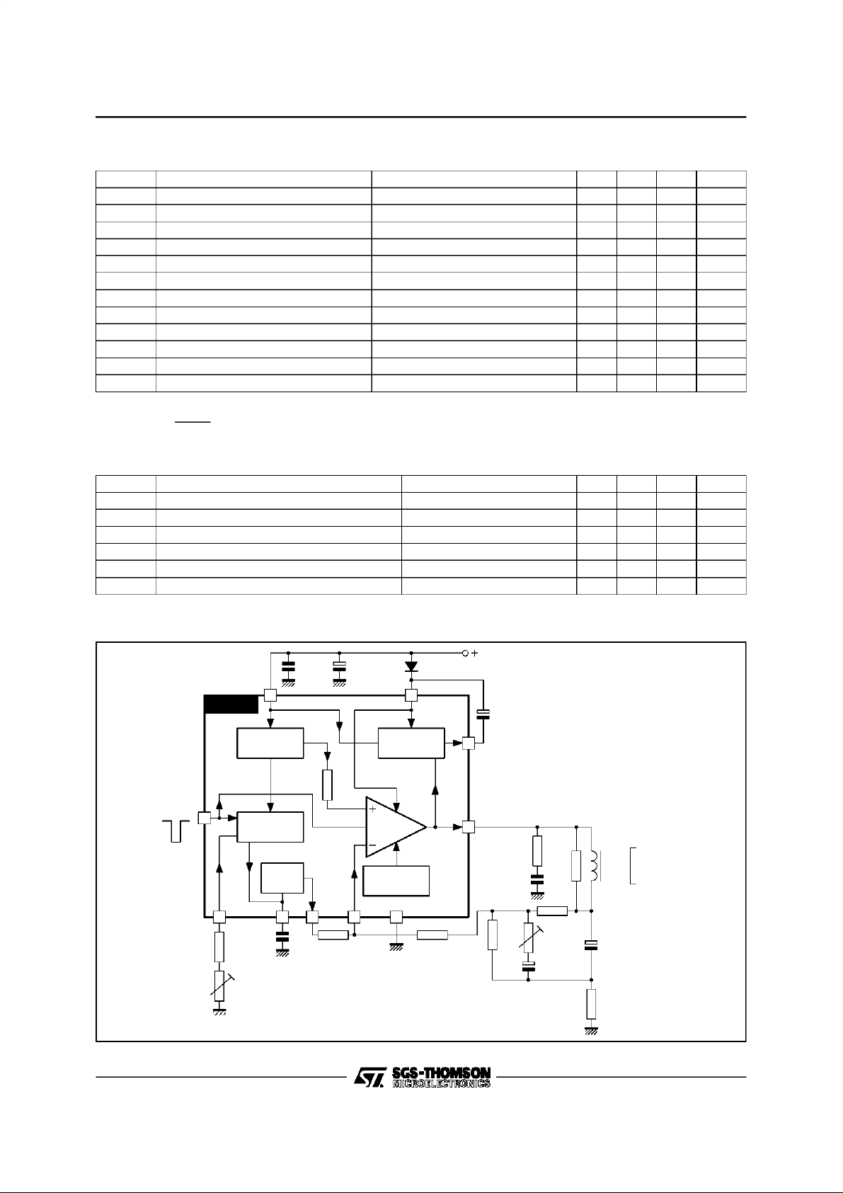
BLOCK DIAGRAM
FLYBACK
GENERATOR
POWER
AMP.
THERMAL
68
2
11
1
TRIG-IN
TDA8174
3
10
VOLTAGE
REGULATOR
RAMP
GENERATOR
BUFFER
STAGE
794
R3
CLOCK
PULSE
PROTECTION
ABSOLUTEMAXIMUMRATINGS
Symbol Parameter Value Unit
V
S
V
1,V2
V
3
V
9
I
0
I
0
I
11
I
11
P
tot
T
stg
T
T
amb
Supply Voltage 35 V
Flyback Peak Voltage 65 V
Trigger Input Voltage 20 V
Amplifier Input Voltage GND, V
S
Output Peak-to-peak Current(non repetitivet = 2ms) 6 A
Output Peak-to-peak Currentt > 10µs4A
Pin 11 DC Current at V1<V
10
Pin 11 Peak-to-peak Current @ t
Total Power Dissipation @ T
tab
< 1.5ms 3 A
fly
=60°C30W
100 mA
Storage Temperature – 40, +150 °C
Junction Temperature 0, +150 °C
j
Ambient Temperature 0, +70 °C
8174-02.EPS
V
8174-01.TBL
THERMALDATA
Symbol Parameter Value Unit
R
th (j-tab)
R
th(j-a)
DC ELECTRICALCHARACTERISTICS (V
Symbol Parameter Test Conditions Min. Typ. Max. Unit
I
2
I
10
–I
7
–I
7
dI
7/I7
V
1
V
1L
V
1H
2/5
Thermal Resistance Junction-tab Max. 3 °C/W
Thermal Resistance Junction-ambient Max. 40 °C/W
=35V ; T
S
=25oC unlessotherwise specified)
amb
Pin 2 Quiescent Current I1=0,I11= 0 16 36 mA
Pin 10 Quiescent Current I1=0,I11= 0 15 30 mA
Ramp GeneratorBias Current V7= 0 0.5 µA
Ramp GeneratorCurrent V7=0,–I4=20µA 18.5 20 21.5 µA
Ramp GeneratorLinearity V6= 0to 15V, –I4=20µA 0.2 1 %
Quiescent Output Voltage Ra= 30kΩ,Rb= 10kΩ,Vs= 35V 17.0 17.8 18.6 V
R
= 6.8kΩ,Rb= 10kΩ,Vs= 15V 7.2 7.5 7.8 V
a
Out SaturationVoltage to GND I1= 0.5A 0.5 1 V
I
= 1.2A 1 1.4 V
1
Out SaturationVoltage to V
s
–I1= 0.5A 1.1 1.6 V
= 1.2A 1.6 2.2 V
–I
1
8174-02.TBL
8174-03.TBL
TDA8174 - TDA8174W
DC ELECTRICALCHARACTERISTICS (continued
Symbol Parameter Test Conditions Min. Typ. Max. Unit
V
dV
dV
V
D11-10
V
G
V
V
V
Notes : 1. The trigger input circuit can accept,with a metal option, positive and negative goinginput pulses.
Reference Voltage –I4=20µA 6.3 6.6 6.9 V
4
Reference Voltage Drift Versus V
4/Vs
Reference Voltage Drift Versus I
4/dI4
V
Internal Reference Voltage 4.26 4.40 4.54 V
r
Vs= 10V to 35V 1 2 mV/V
s
I4=10µAto30µA 1.5 2 mV/µA
4
Diode Fwd Voltage ID= 1.2A 2.2 3 V
Diode Fwd Voltage ID= 1.2A 2.2 3 V
D1-2
Output Stage Open Loop Gain f = 100Hz 60 dB
V
V
fs
11
3
I
3
t
3
2. Th =
Saturation Voltage –I11= 1.2A 1.5 2.5 V
10-11
Pin 11 Scanning Voltage I11= 20mA 1.7 3 V
Trigger Input Threshold (see note 1) 2.6 3.0 3.4 V
Trigger Input Bias Current VIN=V3- 0.2V 30 µA
Trigger Input Width (see note 2) 20 60 Th µS
1.2 ⋅ T
S
where :TSis the vertical period and VPPisramp amplitudeat Pin7
V
PP
8174-04.TBL
AC ELECTRICALCHARACTERISTICS (VS=24V ; T
=25oC unlessotherwise specified)
amb
Symbol Parameter Test Conditions Min. Typ. Max. Unit
V
V
V
T
Operating Supply VoltageRange 10 30 V
s
I
Peak-to-peak Operating Current Range 0.4 A
1
I
Supply Current Iy= 2.4A
s
Flyback Voltage Iy= 2.4A
1
Sawtooth Pedestall Voltage 1.85 V
8
Junction Temp. for Thermal Shutdown 145 °C
js
pp
pp
315 mA
51 V
APPLICATION CIRCUIT
V
S
100µF
35V
11
1
2.2Ω
0.22µF
330
Ω
YOKE
Ry = 9.6
Ω
Ly = 24.6mH
Iy = 1.2App
TRIG-INP
TDA8174
3
10
VOLTAGE
REGULATOR
RAMP
GENERATO R
BUFFER
STAGE
0.1µF 470µF
R3
CLOC K
PULSE
2
FLYBACK
GENERATOR
POWE R
AMP.
THERMAL
PROTECTION
1N4001
8174-05.TBL
180k
220k
794
Ω
Ω
47nF
68
1.2k
1k
Ω
22µF
2.4kΩ
Ω
1500µF
1.2
Ω
8174-03.EPS
3/5

TDA8174 - TDA8174W
PACKAGE MECHANICAL DATA
11PINS - PLASTICMULTIWATT
PM-MW11V.EPS
Dimensions
Min. Typ. Max. Min. Typ. Max.
Millimeters Inches
A 5 0.197
B 2.65 0.104
C 1.6 0.063
D 1 0.039
E 0.49 0.55 0.019 0.022
F 0.88 0.95 0.035 0.037
G 1.45 1.7 1.95 0.057 0.067 0.077
G1 16.75 17 17.25 0.659 0.669 0.679
H1 19.6 0.772
H2 20.2 0.795
L 21.9 22.2 22.5 0.862 0.874 0.886
L1 21.7 22.1 22.5 0.854 0.87 0.886
L2 17.4 18.1 0.685 0.713
L3 17.25 17.5 17.75 0.679 0.689 0.699
L4 10.3 10.7 10.9 0.406 0.421 0.429
L7 2.65 2.9 0.104 0.114
M 4.25 4.55 4.85 0.167 0.179 0.191
M1 4.73 5.08 5.43 0.186 0.200 0.214
S 1.9 2.6 0.075 0.102
S1 1.9 2.6 0.075 0.102
Dia. 1 3.65 3.85 0.144 0.152
MW11V-TBL
4/5

PACKAGE MECHANICAL DATA
11PINS - PLASTICCLIPWATT
TDA8174 - TDA8174W
PM-CW11.EPS
Dimensions
Min. Typ. Max. Min. Typ. Max.
Millimeters Inches
A 3.10 0.122
B 1.10 0.04
C 0.15 0.006
D 1.50 0.059
E 0.52 0.02
F 0.80 0.03
G 1.70 0.066
G1 17.00 0.66
H1 12.00 0.48
H3 20.00 0.79
L 17.90 0.70
L1 14.40 0.57
L2 11.00 0.43
M 2.54 0.1
M1 2.54 0.1
Information furnishedis believed tobe accurateand reliable.However, SGS-THOMSON Microelectronicsassumes no responsibility
for the consequencesof useof suchinformation norfor anyinfringement of patents orother rights ofthird partieswhich may result
from its use. Nolicence is granted byimplication or otherwise under any patent or patentrights of SGS-THOMSON Microelectronics.
Specifications mentioned in this publication are subject to change without notice. This publication supersedes and replaces all
information previously supplied. SGS-THOMSON Microelectronics products arenot authorized for use as critical components inlife
support devices or systems without express written approvalof SGS-THOMSON Microelectronics.
1996 SGS-THOMSON Microelectronics - All RightsReserved
Purchase of I
2
I
C Patent.Rights to use these components ina I2C system,is granted provided that the system conforms to
Australia - Brazil - China- France - Germany - Hong Kong -Italy - Japan - Korea - Malaysia - Malta - Morocco
The Netherlands - Singapore - Spain - Sweden- Switzerland - Taiwan -Thailand - United Kingdom - U.S.A.
2
C Components of SGS-THOMSON Microelectronics, conveys a license under the Philips
2
the I
C Standard Specifications as defined by Philips.
SGS-THOMSON Microelectronics GROUP OF COMPANIES
CW11.TBL
5/5
 Loading...