


.
RAMPGENERATOR
.
INDEPENDENTAMPLITUDEADJUSTEMENT
.
BUFFERSTAGE
.
POWERAMPLIFIER
.
FLYBACKGENERATOR
.
THERMALPROTECTION
.
INTERNAL REFERENCE VOLTAGE DECOUPLING
TDA8174A
TDA8174AW
VERTICALDEFLECTIONCIRCUIT
MULTIWATT11
(Plastic Package)
ORDER CODE :TDA8174A
DESCRIPTION
TDA8174Aand TDA8174AWareamonolithicintegratedcircuits.
It is a full performance and very efficient vertical
deflection circuit intendedfor direct drive of a TV
picturetube in Color andB & W television as well
as in Monitorand Datadisplays.
PIN CONNECTIONS(topview)
10
9
8
7
6
5
4
3
2
1
CLIPWATT11
(Plastic Package)
ORDER CODE :
FLYBACKGENERATOR11
V
S
INVERTING INPUT
BUFFEROUTPUT
RAMPGENERATOR
GROUND
VOLTAGEREF DECOUPLING
HEIGHT ADJUSTMENT
TRIGGERINPUT
OUTPUT STAGEV
POWEROUTPUT
TDA8174AW
S
February 1997
8174A-01.EPS
1/5
TDA8174A- TDA8174AW
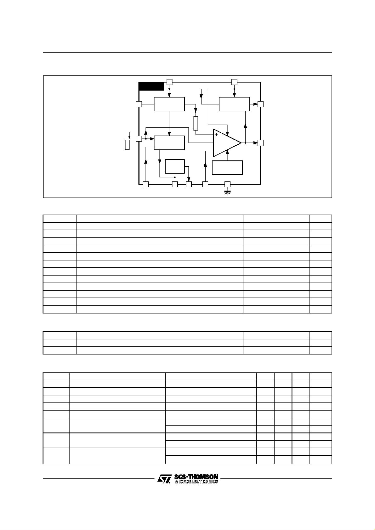
BLOCKDIAGRAM
FLYBACK
GENERATOR
POWER
AMP.
THERMAL
68
2
11
1
TRIG-IN
TDA8174A
5
3
10
VOLTAGE
REGULATOR
RAMP
GENERATOR
BUFFER
STAGE
794
R3
CLOCK
PULSE
PROTECTION
ABSOLUTE MAXIMUMRATINGS
Symbol Parameter Value Unit
V
S
V
1,V2
V
3
V
9
I
0
I
0
I
11
I
11
P
tot
T
stg
T
T
amb
Supply Voltage 35 V
Flyback Peak Voltage 65 V
Trigger Input Voltage 20 V
Amplifier Input Voltage GND, V
S
Output Peak-to-peak Current (non repetitive t = 2ms) 6 A
Output Peak-to-peak Current t > 10µs4A
Pin 11 DC Current at V1<V
10
Pin 11 Peak-to-peak Current @ t
Total Power Dissipation @ T
tab
< 1.5ms 3 A
fly
=60°C30W
100 mA
Storage Temperature – 40, +150
Junction Temperature 0, +150
j
Ambient Temperature 0, +70 °C
8174A-02.EPS
V
C
°
C
°
8174A-01.TBL
THERMAL DATA
Symbol Parameter Value Unit
R
th (j-tab)
R
th(j-a)
DC ELECTRICALCHARACTERISTICS (V
Symbol Parameter Test Conditions Min. Typ. Max. Unit
I
2
I
10
–I
7
–I
7
dI
7/I7
V
1
V
1L
V
1H
2/5
Thermal Resistance Junction-tab Max. 3 °C/W
Thermal Resistance Junction-ambient Max. 40
= 35V ; T
S
=25oC unlessotherwisespecified)
amb
Pin 2 Quiescent Current I1=0,I11= 0 16 36 mA
Pin 10 Quiescent Current I1=0,I11= 0 15 30 mA
Ramp GeneratorBias Current V7= 0 0.5 µA
Ramp GeneratorCurrent V7=0,–I4=20µA 18.5 20 21.5
Ramp GeneratorLinearity V6= 0 to 15V,–I4=20µA 0.2 1 %
Quiescent Output Voltage Ra= 30kΩ,Rb= 10kΩ,Vs= 35V 17.0 17.8 18.6 V
R
= 6.8kΩ,Rb= 10kΩ,Vs= 15V 7.2 7.5 7.8 V
a
Out Saturation Voltage to GND I1= 0.5A 0.5 1 V
I
= 1.2A 1 1.4 V
1
Out Saturation Voltage to V
s
–I1= 0.5A 1.1 1.6 V
–I
= 1.2A 1.6 2.2 V
1
C/W
°
8174A-02.TBL
A
µ
8174A-03.TBL

TDA8174A- TDA8174AW
DC ELECTRICALCHARACTERISTICS
(continued
Symbol Parameter Test Conditions Min. Typ. Max. Unit
V
dV
dV
V
V
D11-10
V
G
V
V
V
Notes :
AC ELECTRICALCHARACTERISTICS
Reference Voltage –I4=20µA 6.3 6.6 6.9 V
4
Reference Voltage Drift Versus V
4/Vs
Reference Voltage Drift Versus I
4/dI4
Internal Reference Voltage 4.25 4.45 4.65 V
5
Vs= 10Vto 35V 1 2 mV/V
s
I4=10µAto30µA 1.5 2 mV/µA
4
Diode Fwd Voltage ID= 1.2A 2.2 3 V
Diode Fwd Voltage ID= 1.2A 2.2 3 V
D1-2
Output Stage Open Loop Gain f = 100Hz 60 dB
V
V
fs
11
3
I
3
t
3
1. The triggerinput circuit can accept, with a metal option, positive andnegative going input pulses.
2. Th
Saturation Voltage –I11= 1.2A 1.5 2.5 V
10-11
Pin 11 Scanning Voltage I11= 20mA 1.7 3 V
Trigger Input Threshold (see note 1) 2.6 3.0 3.4 V
Trigger Input Bias Current VIN=V3- 0.2V 30 µA
Trigger Input Width (see note 2) 20 60 Th
1.2 ⋅ T
S
=
where : TSis the vertical periodand VPPis ramp amplitude at Pin7
V
PP
(V
= 24V ; T
S
amb
=25oC unlessotherwisespecified)
Symbol Parameter Test Conditions Min. Typ. Max. Unit
V
V
V
T
Operating Supply Voltage Range 10 30 V
s
I
Peak-to-peak Operating Current Range 0.4 A
1
I
Supply Current Iy= 2.4A
s
Flyback Voltage Iy= 2.4A
1
Sawtooth Pedestall Voltage 1.85 V
8
Junction Temp. for ThermalShutdown 145
js
pp
pp
315 mA
51 V
S
µ
°
8174A-04.TBL
C
8174A-05.TBL
APPLICATION CIRCUIT
TDA8174A
5
10
µF
TRIG-INP
180k
220kΩ
3
Ω
10
VOLTAGE
REGULATOR
RAMP
GENERATOR
BUFFER
STAGE
794
47nF
0.1µF 470µF 1N4001
2
FLYBACK
GENERATOR
R3
CLOCK
PULSE
POWER
AMP.
THERMAL
PROTECTION
68
11
1
1.2kΩ
V
S
100µF
35V
2.2
Ω
Ω
330
0.22µF
Ra
1kΩ
Rb
22µF
2.4kΩ
1500
µF
1.2Ω
YOKE
Ry = 9.6
Ω
Ly = 24.6mH
Iy = 1.2App
8174A-03.EPS
3/5

TDA8174A- TDA8174AW
PACKAGEMECHANICAL DATA
11PINS - PLASTICMULTIWATT
PM-MW11V.EPS
Dimensions
Min. Typ. Max. Min. Typ. Max.
Millimeters Inches
A 5 0.197
B 2.65 0.104
C 1.6 0.063
D 1 0.039
E 0.49 0.55 0.019 0.022
F 0.88 0.95 0.035 0.037
G 1.45 1.7 1.95 0.057 0.067 0.077
G1 16.75 17 17.25 0.659 0.669 0.679
H1 19.6 0.772
H2 20.2 0.795
L 21.9 22.2 22.5 0.862 0.874 0.886
L1 21.7 22.1 22.5 0.854 0.87 0.886
L2 17.4 18.1 0.685 0.713
L3 17.25 17.5 17.75 0.679 0.689 0.699
L4 10.3 10.7 10.9 0.406 0.421 0.429
L7 2.65 2.9 0.104 0.114
M 4.25 4.55 4.85 0.167 0.179 0.191
M1 4.73 5.08 5.43 0.186 0.200 0.214
S 1.9 2.6 0.075 0.102
S1 1.9 2.6 0.075 0.102
Dia. 1 3.65 3.85 0.144 0.152
MW11V-TBL
4/5

TDA8174A- TDA8174AW
PACKAGEMECHANICAL DATA
11PINS - PLASTICCLIPWATT
Dimensions
Min. Typ. Max. Min. Typ. Max.
A 3.10 0.122
B 1.10 0.04
C 0.15 0.006
D 1.50 0.059
E 0.52 0.02
F 0.80 0.03
G 1.70 0.066
G1 17.00 0.66
H1 12.00 0.48
H3 20.00 0.79
L 17.90 0.70
L1 14.40 0.57
L2 11.00 0.43
M 2.54 0.1
M1 2.54 0.1
Millimeters Inches
PM-CW11.EPS
CW11.TBL
Informationfurnished is believed tobe accurateand reliable. However, SGS-THOMSONMicr oelectronics assumesno responsibility
for theconsequences of use of such information nor for any infringement of patents or other rights of third parties whichmay result
from itsuse. No licence isgrantedby implication orotherwise underany patent or patent rights of SGS-THOMSON Microelectronics.
Specifications mentioned in this publication are subject to change without notice. This publication supersedes and replaces all
informationpreviouslysupplied. SGS-THOMSON Microelectronics products arenot authorized for use as criticalcomponents in life
support devices or systems without express written approval of SGS-THOMSON Microelectronics.
1997 SGS-THOMSON Microelectronics - All Rights Reserved
2
Purchase of I
2
I
C Patent. Rights to use these components in a I2C system,is granted provided that the system conforms to
Australia - Brazil - Canada - China - France - Germany - Hong Kong - Italy - Japan - Korea - Malaysia - Malta- Morocco
The Netherlands - Singapore - Spain - Sweden - Switzerland - Taiwan - Thailand - UnitedKingdom - U.S.A.
C Components of SGS-THOMSON Microelectronics, conveys a license under the Philips
2
C Standard Specifications as defined by Philips.
the I
SGS-THOMSON Microelectronics GROUP OF COMPANIES
5/5
 Loading...