

MULTIFUNCTION DUAL BRIDGE POWER AMPLIFIER
WITH INTEGRATED DIGITAL DIAGNOSTICS
■
DMOS POWER OUTPUT
■
NON-SWITCHING HI-EFFICIENCY
■
SINGLE-CHANNEL 1Ω DRIVING CAPABILITY
■
HIGH OUTPUT POWER CAPABI L ITY 2x28W/
4Ω @ 14.4V, 1KHZ, 10% THD, 2x40W/4Ω EIAJ
■
MAX. OUTPUT POWER 2x75W/2
■
SINGLE-CHANNEL 1Ω DRIVING CAPABILITY
– 84W UNDISTORTED POWER
– FULL I
2
C BUS DRIVING WITH 4 ADDRESS
POSSIBILITIES:
– ST-BY, PLAY/MUTE, GAIN 12/26dB, FULL
DIGITAL DIAGNOSTIC
■
POSSIBILITY TO DISABLE THE I2C
■
DIFFERENTAL INPUTS
■
FULL FAULT PROTECTION
■
DC OFFSET DETECTION
■
TWO INDEPENDENT SHORT CIRCUIT
PROTECTIONS
■
CLIPPING DETECTOR PIN WITH
SELECTABLE THRESHOLD (2%/10%)
■
ST-BY/MUTE PINS
DESCRIPTION
The TDA7575 is a new BCD technology DUAL
BRIDGE type of car radio amplifier in PowerSO36
package specially i ntended for car radio applicati ons.
Ω,
1x150W/1
Ω
TDA7575
MULTIPOWER BCD TECHNOLOGY
MOSFET OUTPUT POWER STAGE
PowerSO36 (Slug up)
ORDERING NUMBER: TDA7575
Thanks to the DMOS output stage the TDA7575 has
a very low distortion allowing a clear powerful sound.
Among the features, its superior efficiency performance coming from the internal exclusive structure,
makes it the most suitabl e devic e to si mplify the ther mal management in high power sets.The dissipated
output power under average listening condition is in
fact reduced up to 50% when compared to the level
provided by conventional class AB solutions.
This device is equipped with a full diagnostic array
that communicates the status of each speaker
through the I
bility of driving loads down to 1
into a single channel. It is also possible to disable the
I2C and co ntrol the TDA7 575 by mean s of t he u sual STBY and MUTE pins.
2
C bus.
The TDA7575 has al so the possi-
Ω
paralleling the outputs
BLOCK DIAGRAM
V
ADDRESS
A B CLK
I2CBUS
IN1+
IN1-
IN2+
IN2-
SVR S_GND
ST-BY/HE 1Ω MUTE
October 2002
This is preliminary information on a new product now in development. Details are subject to change without notice.
S
DAT A VCC CD_OUT
CLIP
DETECTOR
SHORT CIRCUIT
PROTECTION
SHORT CIRCUIT
PROTECTION
PW_GND TAB
OUT1+
OUT1-
OUT2+
OUT2-
2
C EN
I
D01AU1269
1/17
TDA7575
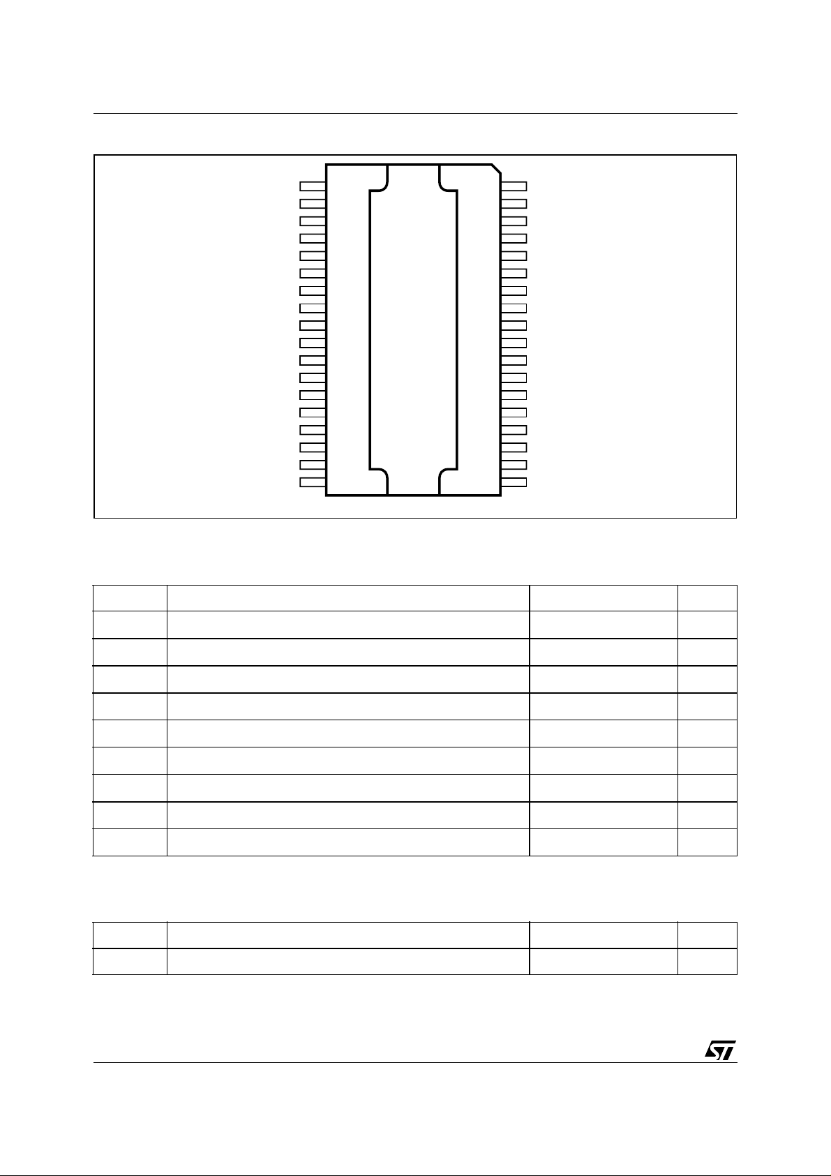
PIN CONNECTION
(Top view)
OUT1+
OUT1+
PWGND
PWGND
PWGND
PWGND
OUT2+
OUT2+
VCC
VCC
OUT1OUT1OUT2OUT2-
VCC
VCC
36
35
34
33
B
A
32
31
30
29
28
26
25
23
22
21
20
19
D01AU1270
1
2
3
4
5
6
7
8
9
1027
11
12
1324
14
15
16
17
18
TAB
IN1+
IN1MUTE
ST_BY
SGND
DATA
CK
N.C.
N.C.
N.C.
N.C.
SVR
CD-OUT
1-OHM
I2C-EN
IN2IN2+
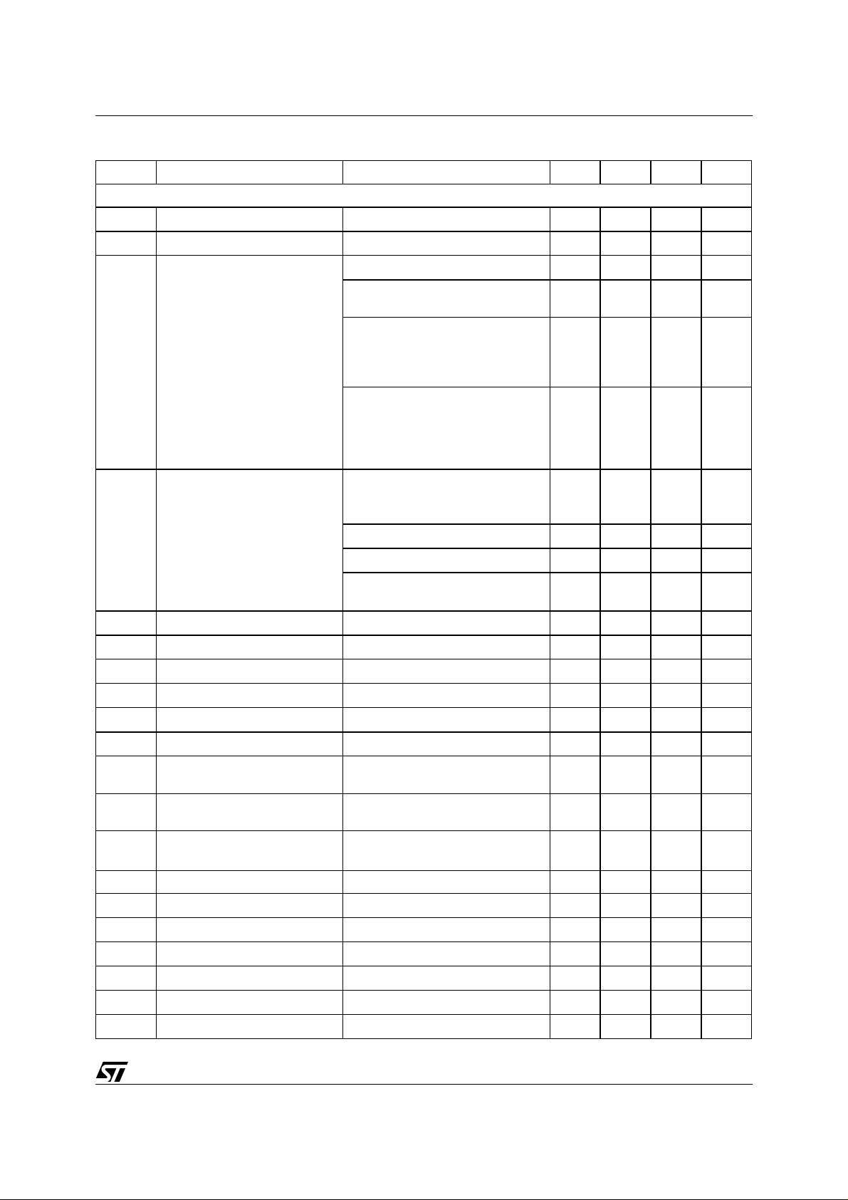
ABSOLUTE MAXIMUM RATINGS
Symbol Parameter Value Unit
V
op
V
V
peak
V
CK
V
DA TA
I
O
I
O
P
tot
T
stg
Operating Supply Voltage 18 V
DC Supply Voltage 28 V
S
Peak Supply Voltage (for t = 50ms) 50 V
CK pin Voltage 6 V
Data Pin Voltage 6 V
Output Peak Current (not repetitive t = 100ms) 8 A
Output Peak Current (repetitive f > 10Hz) 6 A
Power Dissipation T
= 70°C 86 W
case
, TjStorage and Junction Temperature -55 to 150 °C
THERMAL DATA
Symbol Parameter Value Unit
Rth j-case Thermal Resistance Junction-case Max 1 °C/W
2/17
TDA7575
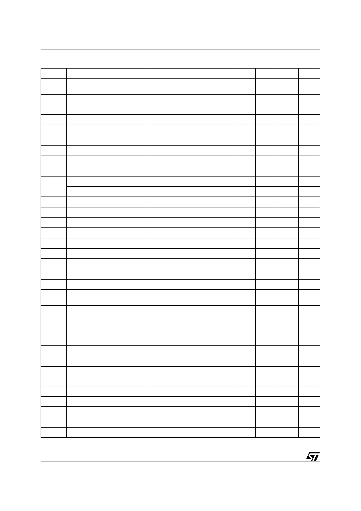
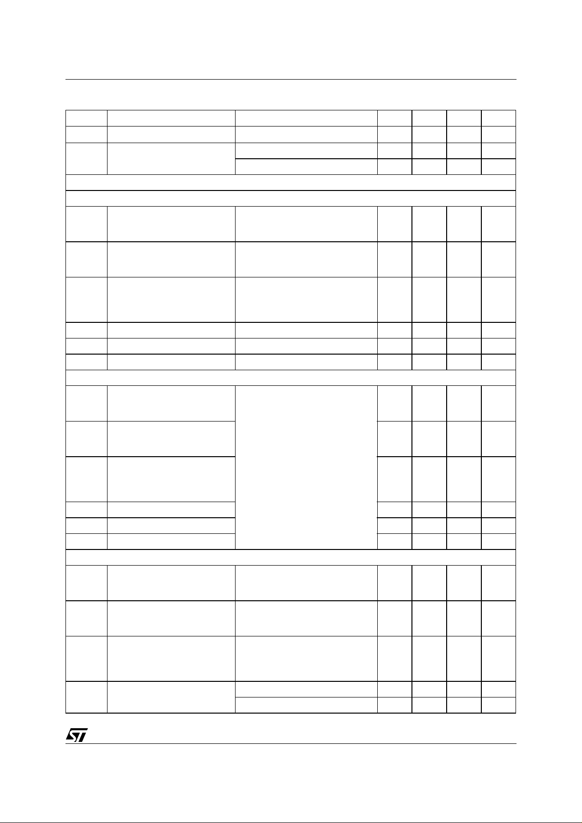
ELECTRICAL CHARACTERISTCS:
(VS=14.4V; f=1KHz; RL=4Ω; Tamb= 25°C unless otherwise specified)
Symbol Parameter Test Condition Min. Typ. Max. Unit
POWER AMPLIFIER
V
Po Output Power EIAJ (V
Supply Voltage Range 8 18 V
S
I
Total Quiescent Drain Current 50 130 200 mA
d
= 13.7V) 35 40 W
S
THD = 10%
THD = 1%; BTL MODE
RL = 2Ω; EIAJ (VS = 13.7V)
RL = 2Ω; THD 10%
RL = 2Ω; THD 1%
RL = 2Ω; MAX POWER
25 28
22
60
45
65
50
37
70
75
Single channel configuration
= 1Ω;
L
= 4-8W
O
= 1; PO = 4-30W
L
125
80
140
130
84
150
0.03
0.03
0.1
0.1
0.5
0.02 0.1 %
40 60 µV
THD Total Harmonic Distortion P
C
R
G
∆G
G
∆G
E
Cross Talk Rg = 600Ω; PO = 1W 60 75 dB
T
Input Impedance 60 100 13 0 KΩ
IN
Voltage Gain 1 (default) 25 26 27 dB
V1
Voltage Gain Match 1 -1 0 1 dB
V1
Voltage Gain 2 11 12 13 dB
V2
Voltage Gain Match 2 -1 0 1 dB
V2
Output Noise Voltage Gain 1 Rg = 600Ω; Gv = 26dB
IN1
(1Ω pin >2.5V); R
EIAJ (VS = 13.7V)
THD 3%
MAX POWER
= 1-12W; STD MODE
O
HE MODE; PO = 1-2W
HE MODE; P
= 1-12W, f = 10kHz 0.15 0.5 %
P
O
R
= 2; HE MODE; Po = 3W 0.03 0.5 %
L
Single channel configuration
(1Ω pin >2.5V); R
filter 20 to 22kHz
E
Output Noise Voltage Gain 2 Rg = 600Ω; Gv = 12dB
IN2
15 25 µV
filter 20 to 22kHz
SVR Supply Voltage Rejection f = 100Hz to 10kHz; V
= 1Vpk;
r
50 60 dB
Rg = 600Ω
W
W
W
W
W
W
W
W
W
%
%
%
BW Power Bandwidth (-3dB) 100 KHz
A
I
A
V
V
CMRR Input CMRR V
Stand-by Attenuation 90 100 dB
SB
Stand-by Current Consumption 2 20 µA
SB
Mute Attenuation 80 90 dB
M
Offset Voltage Mute & Play -100 0 100 mV
OS
Min. Supply Mute Threshold 7 7.5 8 V
AM
= 1Vpk-pk; Rg = 0 Ω 50 60 dB
CM
3/17
TDA7575
ELECTRICAL CHARACTERISTCS:
(continued)
Symbol Parameter Test Condition Min. Typ. Max. Unit
V
Maximum common mode input
MC
f = 1kHz 1 Vrms
level
SR Slew Rate 1.5 4 V/µs
∆V
∆V
T
T
V
V
V
V
V
V
V
I2C I2C pin current (stby) 0V < I2C EN < 18V, V
I2C I2C pin current (operative) I2C EN <18V, V
V
1OHM
V
1OHM
Mute/Unmute Transient A-weighted -100 0 10 0 mVpp
PM
Mute/Stand-by Transient A-weighted -100 0 100 mVpp
TO
Turn on Delay D2 (IB1) 0 to 1 15 40 ms
ON
Turn off Delay D2 (IB1) 1 to 0 15 40 ms
OFF
St-By pin for St-By 0 1.5 V
OFF
St-By pin for standard bridge 3.5 5 V
SB
St-By pin for Hi-eff 7 1 8 V
HE
I
St-By pin Current 1.5 < V
O
St-By Pin Current V
Mute pin voltage for mute mode 0 1.5 V
m
Mute pin voltage for play mode 3.5 18 V
m
I
Mute pin current (ST_BY) V
m
I
Mute pin current (operative) 0V < V
m
I2C pin voltage for I2C disabled 0 1.5 V
I2C
I2C pin voltage for I2C enabled 2.5 18 V
I2C
< 1.5V -10 0 10 µA
stby
= 0V, V
mute
< 18V 7 160 200 µA
stby/HE
< 1.5V -5 0 5 µA
stby
mute
< 18V, V
> 3.5V 65 100 µA
stby
< 1.5V -5 0 5 µA
stby
>3.5V 7 11 15 µA
stby
1OHM pin voltage for 2ch mode 0 1.5 V
1OHM pin voltage for 1ohm
2.5 18 V
mode
I
1OHM
I
1OHM
1OHM pin current (stby) 0V < 1OHM <18V, V
1OHM pin current (operative) 1OHM <18V, V
stby
< 1.5V -5 0 5 µA
stby
> 3.5V 7 11 15 µA
La A Pin Voltage Low logic level 0 1.5 V
Ha High logic level 2.5 18 V
Ia A Pin Current (ST-BY) 0V < A < 18V, V
Ia A Pin Current (Operative) A<18V, V
stby
< 1.5V -5 0 5 µA
stby
> 3.5V 7 11 15 µA
Lb B Pin Voltage Low logic level 0 1.5 V
Hb High logic level 2.5 18 V
Ib B Pin Current (ST-BY) 0V < B < 18V, V
Ib B Pin Current (Operative) B < 18V, V
T
T
I
CDH
Thermal warning 150 °C
W
Thermal Protection intervention 170 °C
PI
Clip Pin High Leakage Current CD off, 0V < VCD < 5.5V -15 0 15 µA
stby
< 1.5V -5 0 5 µA
stby
> 3.5V 7 11 15 µA
4/17
TDA7575
ELECTRICAL CHARACTERISTCS:
(continued)
Symbol Parameter Test Condition Min. Typ. Max. Unit
I
CDL
Clip Pin Low Sink Current CD on; VCD < 300mV 1 mA
CD Clip detect THD level D0 (IB1) = 0 0.8 1.3 2.5 %
D0 (IB1) = 1 5 10 15 %
(*) ST-BY Pin high enables I2C bus; ST-BY Pin low puts the device in ST-BY condition.(see “prog” for more details)
TURN ON DIAGNOSTICS
Pgnd Short to GND det. (below this
(Power Amplifier Mode)
Power Amplifier in st-by condition 1.2 V
limit, the Output is considered in
Short Circuit to GND)
Pvs Short to Vs det. (above this
V
-0.9 V
s
limit, the Output is considered in
Short Circuit to VS)
Pnop Normal operation
1.8 V
-1.5 V
s
thresholds.(Within these limits,
the Output is considered
without faults).
Lsc Shorted Load det. 0.5 Ω
Lop Open Load det. 130 Ω
Lnop Normal Load det. 1.5 70 Ω
TURN ON DIAGNOSTICS
Pgnd Short to GND det. (below this
(Line Driver Mode)
Power Amplifier in st-by 1.2 V
limit, the Output is considered in
Short Circuit to GND)
Pvs Short to Vs det. (above this
-0.9 V
V
s
limit, the Output is considered in
Short Circuit to VS)
Pnop Normal operation
1.8 V
-1.5 V
s
thresholds.(Within these limits,
the Output is considered
without faults).
Lsc Shorted Load det. 1.5 Ω
Lop Open Load det. 400 Ω
Lnop Normal Load det. 4.5 200 Ω
PERMANENT DIAGNOSTICS
Pgnd Short to GND det. (below this
limit, the Output is considered in
Short Circuit to GND)
Pvs Short to Vs det. (above this
(Power Amplifier Mode or Line Driver Mode)
Power Amplifier in Mute or Play
condition, one or more short circuits
protection activated
1.2 V
Vs - 0.9
limit, the Output is considered in
Short Circuit to VS)
Pnop Normal operation
1.8 V
-1.5 V
s
thresholds.(Within these limits,
the Output is considered
without faults).
Lsc Shorted Load det. Pow. Amp. mode 0.5 Ω
Line Driver mode 1.5 Ω
V
5/17

TDA7575
ELECTRICAL CHARACTERISTCS:
Symbol Parameter Test Condition Min. Typ. Max. Unit
V
2
C BUS INTERFACE
I
f
SCL
V
V
Offset Detection Power Amplifier in play condition
O
Clock Frequency 400 KHz
Input Low Voltage 1.5 V
IL
Input High Voltage 2.3 V
IH
(continued)
±1.5 ±2 ±2.5 V
AC Input signals = 0
I2C BUS INTERFACE
Data transm ission f rom mic roproc esso r to the TDA7575 an d viceve rsa take s place t hr ough the 2 wi res I2C BUS interface, consisting of the two lines SDA and SCL (pull-up resistors to positi ve supply voltage must be connected).
Data Validity
As shown by fig. 1, the data on the SDA line must be stable during the high period of the clock.
The HIGH and LOW state of the data line can only change when the clock signal on the SCL line is LOW.
Start and Stop Conditions
As shown by fig. 2 a start condition is a HIGH to LOW transition of the SDA line while SCL is HIGH.
The stop condition is a LOW to HIGH transition of the SDA line while SCL is HIGH.
Byte Format
Every byte transferred to the SDA line must contain 8 bits. Each byte must be followed by an acknowledge bit.
The MSB is transferred first.
Acknowledge
The transmitter* puts a resistive HIGH level on the SDA line during the acknowledge c lock pulse ( see fig.3). The
receiver** the acknowledges has to pull- down (LOW) the SDA line during the acknowledge cloc k pulse, so that
the SDAline is stable LOW during this clock pulse.
* Transmitter
= master (
= slave (TDA7575) when the
µ
P) when it writes an address to the TDA7575
µ
P reads a data byte from TDA7575
** Receiv er
= slave (TDA7575) when the
µ
P writes an address to the TDA7575
= master (mP) when it reads a data byte from TDA7575
6/17
 Loading...