

.
QUADRATURE INTERCARRIER DEMODULATOR
.
VERYHIGHINPUTSENSITIVITY
.
GOODSIGNALTO NOISE RATIO
.
FASTAVERAGINGAGC
.
IF AMPLIFIERCAN BE SWITCHED OFF FOR
VTRMODE
.
GOODAM SUPPRESSION
.
OUTPUT SIGNAL STABILIZED AGAINST
SUPPLY VOLTAGEVARIATIONS
.
VERYFEW EXTERNALCOMPONENTS
DESCRIPTION
TDA4445A:
Sound IF amplifier, with FM processing for quasi
parallelsound system.
TDA4445B:
Sound IF amplifier, with FM processing and AM
demodulator, for multi-standard sound TV appliances.
TDA4445Badditionnal:
Bistandardapplications(B/G and L)
No adjustmentofthe AMdemodulator
Low AMdistortion
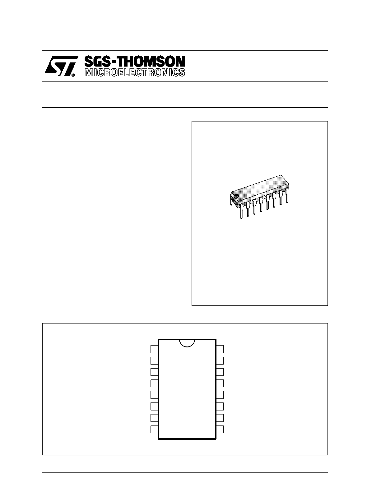
TDA4445A
TDA4445B
SOUNDIF AMPLIFIER
DIP16
(Plastic Package)
ORDER CODE : TDA4445A - TDA4445B
PIN CONNECTIONS
NOT TOBE CONNECTED
IF AGC TIMECONSTANT
NOT TO BE CONNECTED
NOT TO BE CONNECTED FOR TDA4445A
AVERAGING CAPACITOR FOR TDA4445B
NOT TO BE CONNECTED FOR TDA4445A
A.F. SOUND OUTPUT FOR TDA4445B
NOT TOBE CONNECTED
REFERENCE L.C.NETWORK REFERENCE L.C. NETWORK
December 1992
IF INPUT
1
2
3
4
5
6
7
8
16
15
14
13
12
11
10
IF INPUT
NOT TO BE CONNECTED
NOT TO BE CONNECTED
GROUND
FM MODULATED SOUND OUTPUT
SUPPLY VOLTAGE
NOT TO BE CONNECTED
9
4445-01.EPS
1/6
TDA4445A - TDA4445B
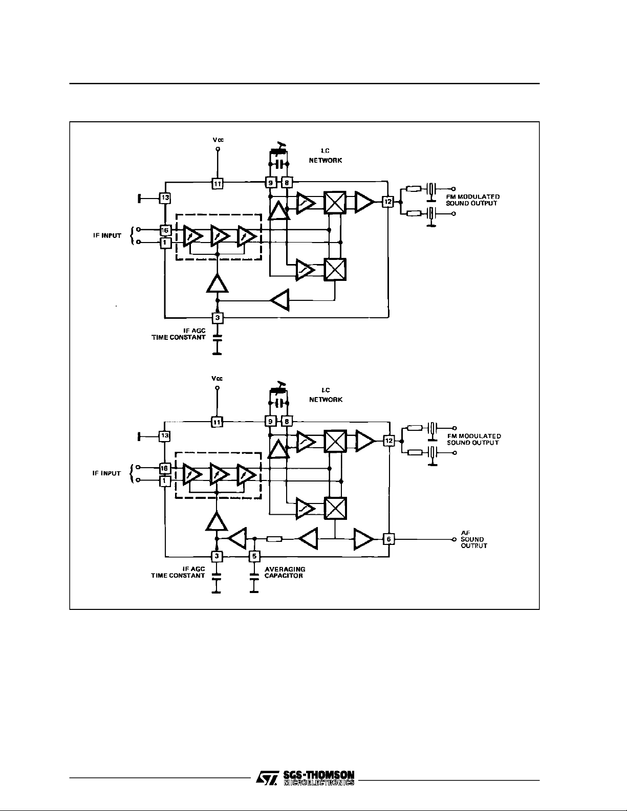
BLOCK DIAGRAMS
TDA4445A
TDA4445B
GENERALDESCRIPTION
This circuit includesthe followingfunctions:
.
Three symmetrical and gain controlled wide
band amplifier stages, which are extremely stable by quasiDC couplingwithoutfeedback.
.
AveragingAGCwith dischargecontrolcircuit
.
AGCvoltage generator
Quasi parallel sound operation:
.
High phase accuracy of the carriersignal proc-
essing,independentfrom AM
.
Linearquadraturedemodulator
.
Sound-IF-amplifier stage with impedance converter
AM-Demodulation (onlyTDA4445B) :
.
Carriercontrolleddemodulator
.
Audio frequency stage with impedance converter
.
AveraginglowpassAGC
4445-02.EPS/ 4445-03.EPS
2/6

TDA4445A - TDA4445B
ABSOLUTE MAXIMUMRATINGS
Symbol Parameter Value Unit
V
CC
I
CC
V
ext
V
ext
P
tot
T
T
amb
T
stg
THERMALDATA
Symbol Parameter Value Unit
R
th(j-a)
ELECTRICALOPERATING CHARACTERISTICS
=+25°C, VCC=12V (unlessotherwisespecified)
T
amb
Symbol Parameter Min. Typ. Max. Unit
DC CHARACTERISTICS
V
CC
I
CC
V
O
I Output DC Current (V
R Input Impedance Pins 1-16 2
C Input Impedance Pins 1-16 2 pF
V Switch off Control Voltage for VTR Mode Pin 3 9 10 V
I Switch off Control Current for VTR Mode Pin 3 150 µ
AGC CHARACTERISTICS
∆
GIF
QUASI PARALLEL SOUND OPERATION
= 38.9MHz, f
(f
PC
V
I
V
I
V
O
S + N
N
AM DEMODULATI0N (TDA4445B only) (f
V
I
V
O
I Output DC Current (V
d Distortion (V
V
O
Supply Voltage Range Pin 11 15 V
Supply Current Pin 11 70 mA
External Voltages Pin 3
Pin 12
External Voltages TDA4445A - TDA4445B
TDA4445B
Pin 5
Pin 6
12
8
8
8
Power Dissipation 1 W
Junction Temperature 125 °
j
Ambient TemperatureRange 0, + 70 °
Storage Temperature Range – 25, + 125 °
Junction-ambient Thermal Resistance 70 °
Supply Voltage Pin 13 10 12 15 V
Supply Current (V3= 3.5V) Pin 11 45 60 mA
DC Output Voltage (V3= 3.5V) Pin 12 4.25 5 5.75 V
= 3.5VV11= 12V) Pin 12 1 2 mA
3
IF AGC Range 62 dB
= 33.4MHz, f
SC1
= 33.16MHz, PC/SC1= 13dB, PC/SC2 = 20dB, PC unmodulated)
SC2
Min. Input Voltage(5.5MHz - Output Signal - 3dB) Pins 1-16 70 µ
Max. Input Voltage (5.5MHz - Output Signal + 1dB) Pins 1-16 90 mV
Sound-IF-output Voltage (V
5.5MHz Output Voltage
5.74MHz Output Voltage
Signal to noise ratio measured according to CCIR 468-2
Picture Modulation Ratio 90%,Reference signal (V
FM-frequency deviation30kHz ➝ Out 1 350mV
f
= 1kHz, measured at audio-output Out 2 350mV
mod
Black Screen (1. Channel/2. Channel)
Grid Screen (1. Channel/2. Channel)
= 20mV
1-16
= 39.2MHz, m = 80%, f
SC
SC unmodulated)
eff
1-16
= 10mV),
RMS
RMS
= 1kHz)
mod
Pin 12
200
100
Pin 12
55/50
45/40
Min. Input Voltage(Audio Output Signal - 3dB) Pins 1-16 70 µ
Output DC Voltage (V
= 10mV, f
1-16
AF Output Voltage (V
= 10mV
1-16
= 7.5V, V3= 3.5V) Pin 6 0.3 1.2 mA
6
mod
= 100mV
1-16
unmodulated) Pin 6 3.3 4.5 V
eff
= 1kHz , m = 80%) Pin 6 2.5 4 %
, m = 50% , f
eff
= 10kHz) Pin 6 500 700 900 mV
mod
400
300
V
V
V
V
C
C
C
C/W
kΩ
V
mV
mV
dB
dB
V
4445-01.TBL
4445-02.TBL
A
eff
eff
eff
eff
eff
eff
4445-03.TBL
3/6

TDA4445A - TDA4445B
TYPICALAPPLICATION
Figure 1 : QuasiParallel Sound Operation
4/6
4445-04.TIF

TYPICALAPPLICATION
Figure 2 : BistandardOperation(FM stereosound+ AM sound)
TDA4445A - TDA4445B
5/6
4445-05.TIF

TDA4445A - TDA4445B
PACKAGE MECHANICAL DATA
16 PINS- PLASTICDIP
I
L
b1
E
Dimensions
a1
Z
b
16
18
Be
e3
D
9
F
Millimeters Inches
Min. Typ. Max. Min. Typ. Max.
a1 0.51 0.020
B 0.77 1.65 0.030 0.065
b 0.5 0.020
b1 0.25 0.010
D 20 0.787
E 8.5 0.335
e 2.54 0.100
e3 17.78 0.700
F 7.1 0.280
i 5.1 0.201
L 3.3 0.130
Z 1.27 0.050
PM-DIP16.EPS
DIP16.TBL
Information furnishedis believed to be accurate andreliable. However, SGS-THOMSONMicroelectronicsassumes no responsibility
for the consequences of use of such information norfor anyinfringement ofpatents or otherrights of third partieswhich may result
from itsuse. Nolicence isgranted by implication or otherwise under any patent orpatentrights of SGS-THOMSON Microelectronics.
Specifications mentioned in this publication are subject to change without notice. This publication supersedes and replaces all
information previouslysupplied. SGS-THOMSON Microelectronics productsare not authorized for use as critical components in life
support devices or systems without express written approval of SGS-THOMSON Microelectronics.
1994 SGS-THOMSON Microelectronics - All RightsReserved
Purchase of I
2
I
C Patent. Rights to use these components in aI2C system, is granted provided that thesystem conforms to
Australia - Brazil - China - France - Germany - Hong Kong - Italy - Japan - Korea- Malaysia - Malta - Morocco
The Netherlands- Singapore - Spain - Sweden - Switzerland -Taiwan - Thailand - United Kingdom - U.S.A.
2
C Components of SGS-THOMSON Microelectronics, conveys a license under the Philips
2
the I
C Standard Specifications as defined by Philips.
SGS-THOMSON Microelectronics GROUP OF COMPANIES
6/6
 Loading...