


1/205
ST20-C1 Core
Instruction Set
Reference Manual
72-TRN-274-01 July1997

Contents
2/205
Contents
1 Introduction . . . . . . . . . . . . . . . . . . . . . . . . . . . . . . . . . . . . . . . . . . . . . . . . . . . .4
1.1 ST20-C1 features . . . . . . . . . . . . . . . . . . . . . . . . . . . . . . . . . . . . . . . . . . . .4
1.2 Manual structure. . . . . . . . . . . . . . . . . . . . . . . . . . . . . . .. . . . . . . . . . . . . .5
2 Notation . . . . . . . . . . . . . . . . . . . . . . . . . . . . . . . . . . . . . . . . . . . . . . . . . . . . . . .6
2.1 Instruction listings . . . . . . . . . . . . . . . . . . . . . . . . . . . . . . . . . . . . . . . . . . . .6
2.2 Instruction definitions . . . . . . . . . . . . . . . . . . . . . . . . . . . ..............8
2.3 Operators used in the definitions .. . . . . . . . . . . . . . . . . . . . . . ........11
2.4 Data structures and constants . .. . . . . . . . . . . . . . . . . . . . . . . . . . . . . . .13
3 Architecture . . . . . . . . ...........................................16
3.1 Values. . . . . . . . . . . . . . ......................................16
3.2 Memory. . . . . . . . . . . . . . . . . . . . . . . . . . . . . . . . . . . . . . . . . . . . .......18
3.3 Registers. . . . . . . . . . . . . . . . . . . . . . . . . . . . . . . . . . . . . . . . . . . . . . . . . .20
3.4 Instruction encoding . . . . . . . . . . . . . . . . . . . . . . . . . . . . . . . . . . . . . . . . .24
4 Using ST20-C1 instructions ......................................30
4.1 Manipulating the evaluation stack. . . . . . . . . . . . . . . . . . . . . . . . . . . . . . .30
4.2 Loading and storing . . . . . . . . . . . . . . . . . . . . . . . . . . . . . . . . . . . . . . . . .31
4.3 Expression evaluation.. . . . . . . . . ..............................33
4.4 Arithmetic . . . . . . . . . . . . . . . . . . . . . . . . . . . . . . . . . . . . . . . . . . . . . . . . .35
4.5 Forming addresses . . . . . . . . . . . . . . . . . .........................41
4.6 Comparisons and jumps . . . ...................................43
4.7 Evaluation of boolean expressions . . . . . . . . . . . . . . . . . . . . . . . . . . . . . .45
4.8 Bitwise logic and bit operations. . . . . . . ..........................47
4.9 Shifting and byte swapping. . . . . . . . . . . . . . . . . . . . . . . . . . . . . . . . . . . .48
4.10 Function and procedure calls . . . . . . . . . . . . . . . . . . . . . . . . . . . . . . . . . .48
4.11 Peripherals and I/O. . . . . . . . . . ................................52
4.12 Status register. . . . . . . . . . . . . . . . . . . . . . . . . . . . . . . . . . . . . . . . . . . . . .55
5 Multiply accumulate . . . . . .......................................56
5.1 Data formats. . . . . . . . . . . . . . . . . . . . . . . . . . . . . . . . . . . . . . . . . . . . . . .56
5.2 mac and umac . . . . . . . . . . . . . . . . . . . . . . . . . . . . . . . . . . . ..........56
5.3 Short multiply accumulate loop. . . . . . . . . . . . . . . . . . . . . . . . . . . . . . . . .56
5.4 Biquad IIR filter . . . . . . . . . . . . . . . . . . . . . . . . . . . . . . . . . . . . . . . . . . . . .58
5.5 Data vectors . . . . . . . . . . . . . . . . . . . . . . . . . . . . . . . . . . . . . . . . . . . . . . .59
5.6 Scaling . . . . . . . . . . . . . . . . . . . . . .. . . . . . . . . . . . . . . . . . . . . . . . . . . . .59
5.7 Data formats. . . . . . . . . . . . . . . . . . . . . . . . . . . . . . . . . . . . . . . . . . . . . . .65

3/205
Contents
6 Exceptions . . . . . . . . . . . . . . . . . . . . . . . . . . . . . . . . . . . . . . . . . . . . . . . . . . . .70
6.1 Exception levels . . . . . . . . . . . . . . . . . . . . . . . . . . . . . . . . . . . . . . . . . . . .71
6.2 Exception vector table. . . .....................................72
6.3 Exception control block and the saved state. . . ....................73
6.4 Initial exception handler state . .................................74
6.5 Restrictions on exception handlers. . . . . . . . . . . . . . . . . . . . . . . . . . . . . .75
6.6 Interrupts. . . . . . . . . . . . . . . . . . . . . . . . . . ........................75
6.7 Traps. . . . . . . . . . . . . . . . . . . . . . . . . . . . . . . . . . . . . . . . . . . . . . . . . . . . .76
6.8 Setting up the exception handler . . . . . . . . . . . . ...................76
7 Multi-tasking . . . . . . . . . . . . . . . . . . . . . . . . . . . . . . . . . . . . . . . . . . . . . . . . . .78
7.1 Processes . . . . . . . . . . . . . . . . . . . . .............................78
7.2 Descheduled processes . . . . . . . . . . . . . . . . . . . . . . . . . . . . . . . . . . . . . .79
7.3 Queues . . . . . . . . . . . . . . . . . . . . . . . . . . . . . . . . . . . . . . . . . . . . . . . . . . .80
7.4 Timeslicing ................................................81
7.5 Inactive processes . . . . . . . . . . ................................82
7.6 Descheduled process state. . . . . . . . . . . . . . .. .. . . . . . . . . .. .. . . . . . .82
7.7 Initializing multi-tasking. . . . . .. . . . . . . . . . . . . . . ..................83
7.8 Scheduling kernels . . . . . . . . . . . . . . . . . . . . . . . . . . . . .. .. . . . . . . . . . .84
7.9 Semaphores . . . . . . . . . . . . . . . . . . . . . . . . . . . . . . . . . . . . ...........84
7.10 Sleep. . . . . . . . . . . . . . . . . . . . . . . . . . . . . . . . . . . . . . . . . . . . . . . . . . . . .85
8 Instruction Set Reference. . . . . . . . . . . . . . . . . . . . . . . . . . . . . . . . . . . . . . . .87
Appendices . ...........................................168
A Constants and data structures. . . . . . . . . . . . . . . . . . . . . . . . . . . . . . . . . . .169
B Instruction set summary. . . . . . . . . . . . . . . . . . . . . . . . . . . . . . . . . . . . . . . .174
C Compiling for the ST20-C1 . . . . . . . . . . . . . . . . . . . . . . . . . . . . . . . . . . . . . .178
D Glossary. . . . . . . . . . . . . . . . . . . . . . . . . . . . . . . . . . . . . . . . . . . . . . . . . . . . .187

1.1 ST20-C1 features
4/205
1 Introduction
This manual provides a summary and reference to the ST20 architecture and instruction set for the ST20-C1 core.
ST20 is a technology for building successful embedded VLSI designs. ST20 devices
comprise a collection of VLSI macro-cells connected through a high-performance onchip bus. This architecture allowsthe easy construction of both general purpose (e.g.
ST20-MC1 micro-controller) and application specific devices (e.g. ST20-TPx digital
set top boxfamily).
The ST20 macro-cell library includes CPU micro-cores, on-chip memories and a wide
range of digital and analogue I/O devices. SGS-THOMSON offers a range of ST20
CPU micro-cores, allowing the best cost vs. performance trade-off to be achieved in
each application area. This manualdescribes the ST20-C1 CPU micro-core.
ST20 devices are available from SGS-THOMSON and licensed second source
vendors.
1.1 ST20-C1 features
The ST20-C1 has the followingfeatures:
• It is implemented as a 2-waysuperscalar,3-stage pipeline,with an internal 16word register cache. This architecture can sustain 4 instructions in progress,
with a maximum of 2 instructions completing per cycle.
• It uses a variable length instruction coding scheme based on 8-bit units which
gives excellent static and dynamic code size. Instructions take between 1 and
8 units to code, with an average of 1.25 units (10 bits) per instruction.
• It provides flexible prioritized vectored interrupt capabilities. The worst case
interrupt latency is 0.5 microseconds (at 33 Mhz operatingfrequency).
• It provides extensive instruction level support for 16-bit digital signal processing (DSP) algorithms.
• It is particularly suitable for low power and battery-powered applications, with
low core operating power,and sophisticated power management facilities.
• It provides extensivereal-time debugging capability through the optional ST20
diagnostic controller unit (DCU) macro-cell, which supports fully non-intrusive
breakpoints, watchpoints and code tracing.
• It has a flexibleand powerful built-in hardware scheduler.This is a light-weight
real-time operating system
(RTOS) directly implemented in the microcode of
the ST20-C1 processor. The hardware scheduler can be customized and provides support for software schedulers.
• It provides a built-in user-programmable32-bit input/output register providing
system control and communication capability directly from the CPU.

5/205
1 Introduction
1.2 Manual structure
The manual is divided into the following chapters:
1 This introduction chapter,which explains the structure of the book;
2 A notation chapter (Chapter 2) which explains the layoutand notation conven-
tions used in the instruction definitionsand elsewhere;
3 An architecture chapter (Chapter 3), which explainsthe structure of the ST20-
C1 core, the registers, memory addressing, the format of the instructions and
the exception handling and process models;
4 Four chapters on using the instructions and howthe instructions can be used
to achievecertain useful outcomes: Chapter 4 on the generalinstructions;
Chapter 5 on multiply-accumulate;Chapter 6 on interrupts and traps; and
Chapter 7 on processes and support formulti-tasking.
5 An alphabetical listing of the instructions, one to a page (Chapter 8). Descrip-
tions and formal definitionsare presented in astandard format with the instruction mnemonic and full name of the instruction at the top of the page.The
notation used is explained in detail in Chapter 2.
In addition there are appendices listing constants and structures, covering issues
related to compiling for a ST20-C1 core and listing the instruction set plus a glossary
for ST20-C1 terminology.

2.1 Instruction listings
6/205
2 Notation
This chapter describes the notation used throughout this manual, including the
meaning of the instruction listings and the meanings and valuesof constants.
2.1 Instruction listings
The instructions are listed in alphabetical order, one to a page. Descriptions are
presented in a standard format with the instruction mnemonic and full name of the
instruction at the top of the page,followedby these categories of information:
• Code: the instruction code;
• Description: a brief summary of the purpose and behavior of the instruction;
• Definition: a more formal and complete description of the instruction, using
the notation described belowin section 2.2;
• Status Register: a list of errors and other changes to the Status Register
which can occur;
• Comments: a list of other important features of the instruction;
• See also: cross referencesare providedto other instructions with related func-
tions.
These categories are explained in more detail below, using the
and
instruction as an
example.
2.1.1 Instruction name
The header at the top of each page shows the instruction mnemonic and, on the right,
the full name of the instruction. For primary instructions the mnemonic is followed by
‘n’ to indicate the operand to the instruction; the same notation is used in the description to show how the operand is used. An explanation of the primary and secondary
instruction formats is givenin section 3.4.
2.1.2 Code
The code of the instruction is the value that would appear in memory to represent the
instruction.
For secondary instructions the instruction ‘operation code’ is shown as the memory
code — the actual bytes, including any prefixes, which are stored in memory. The
value is given as a sequence of bytesin hexadecimal, decoded left to right. The codes
are stored in memory in ‘little-endian’ format, with the first byte at the lowest address.
For example,the entry for the
and
instruction is:
Code:F9
This means that the hexadecimalbyte value F9 would appear in memory foran
and
.

7/205
2 Notation
For primary instructions the code stored in memory is determined partly by the value
of the operand to the instruction. In this case the op-code is shown as ‘Functionx’
wherexis the function code in the last byte of the instruction. For example,
adc(add
constant
) is shownas
Code: Function 8
This means that
adc 1
would appear in memory as the hexadecimal byte value 81. For
an operandnin the range 0 to 15,
adc n
would appear in memory as 8n.
2.1.3 Description
The description section providesan indication of the purpose of the instruction as well
as a summary of the behavior. This may include details of the use of registers, whose
initial values may be used as parameters and into which results may be stored.
Forexample, the
and
instruction contains the followingdescription:
Description: Bitwise AND of Areg and Breg.
2.1.4 Definition
The definition section provides a formal description of the behavior of the instruction.
The behavior is defined in terms of its effect on the state of the processor, i.e. the
changes in the values in registers and memory before and after the instruction has
executed.
The effects of the instruction on registers,etc. are givenas statements of the following
form:
register′←
expression involving registers, etc.
memory_location′←
expression involving registers, etc.
Primed names (e.g. Areg′) represent values after instruction execution, while names
without primes represent values when the instruction execution starts. For example,
Areg represents the value in Areg before the execution of the instruction while Areg′
represents the value in Areg afterwards. So the example above states that after the
instruction has been executed the register or memory location on the left hand side
holds the value of the expressionon the right hand side.
Only the changed registers and memory locations are given on the left hand side of
the statements. If the new value of a register or memory location is not giventhen the
value is unchanged by the instruction.
The description is written with the main function of the instruction stated first. For
example the main function of the
add
instruction is to put the sum of Areg and Breg
into Areg). This is followed by the other effects of the instruction, such as rotating the
stack. There is no temporal ordering implied by the order in which the statements are
written.

2.2 Instruction definitions
8/205
For example,the
and
instruction contains the followingdescription:
Definition:
Areg′←Breg ∧ Areg
Breg′←Creg
Creg′←Areg
This says that the integer stack is rotated and Areg is assigned the bitwise ANDof the
values that were initially in Breg and Areg. After the instruction has executed Breg
contains the value that was originally in Creg, and Creg has the value that was in
Areg.
The notation is described more fully in section 2.2.
2.1.5 Status Register
This section of the instruction definitions lists any changes to bits of the Status
register which can occur. The Status register is described in more detail in section
3.3.2.
2.1.6 Comments
This section is used for listing other information about the instructions that may be of
interest. This includes an indication of the type of the instruction:
“Primary instruction” — indicates one of the 13 functions which maybe directly
encoded with an operand in a single byte instruction.
“Secondary instruction” — indicates an instruction which isencoded using
opr
.
An explanation of the primary and secondary instruction formats is given in section
3.4.
The Comments section also describes any situations where the operation of the
instruction is undefinedor invalidand anylimits to the parameter values.
For example,the only comment listed for the
and
instruction is:
Comments:
Secondary instruction.
This says that
and
is a secondaryinstruction.
2.2 Instruction definitions
The following sections give a full description of the notation used in the formal definition section of the instruction descriptions.

9/205
2 Notation
2.2.1 The process state
The process state consists of the registers (Areg, Breg, Creg, Iptr, Tdesc, Wptr, and
Status), and the contents of memory. A description of the meanings and uses of the
registers and special memory locations and data structures is given in section 3.3.
2.2.2 General
The instruction descriptions are not intended to describe the waythe instructions are
implemented, but only their effect on the state of the processor.So, for example, the
result of
mul
is shown in terms of an intermediate result calculated to infiniteprecision,
although no such intermediate result is used in the implementation.
Comments (in
italics
) are used to both clarify the description and to describe actions
or values that cannot easily be represented by the notation used here; e.g.
take
timeslice trap
. Some of these actions and values are described in more detail in other
chapters.
An ellipsis is used to show a range of values; e.g. ‘i = 0..31’ means that i has values
from 0 to 31, inclusive.
Subscripts are used to indicate particular bits in a word; e.g. Aregiforbit i of Areg;and
Areg
0..7
for the least significantbyte of Areg. Note that bit 0 is the least significant bit
in a word,and bit 31 is the most significantbit.
Except for Iptr, certain reserved words of memory,and taking exceptions or switching
processes, if the description does not mention the state of a register or memory
location after the instruction, then the value will not be changed bythe instruction.
Iptr is assigned the address of the next instruction in the code
before
the instruction
execution starts. The Iptr is included in the description only when there are additional
effects of the instruction (e.g. in the
jump
instruction). In these cases the address of
the next instruction is indicated bythe comment ‘
next instruction
’.
2.2.3 Undefined values
Some instructions in some circumstances leave the contents of a register or memory
location in an undefined state. This means that the value of the location may be
changed by the instruction, but the new value cannot be easily defined, or is not a
meaningful result of the instruction. For example, when division by zero is attempted,
Breg and Creg become undefined, i.e. they do not contain any meaningful data. An
undefinedvalue is represented by the name
undefined
.
The values of registers which become undefined as a result of executing an instruction are implementation dependent and are not guaranteed to be the same on
different members or revisions of the ST20 family of processors.
2.2.4 Data types
The instruction set includes operationson three sizesof data: 8, 16 and 32-bit objects.
8-bit and 16-bit data can represent signed or unsigned integers and 32-bit data can

2.2 Instruction definitions
10/205
represent addresses,signed or unsigned integers. Generally the arithmetic in signed.
In some cases it is clear from the context (e.g. from the operators used) whether a
particular object represents a signed or unsigned number. A subscripted label is
added (e.g. Areg
unsigned
) to clarify where necessary.
2.2.5 Representing memory
The memory is represented by arrays of each data type. These are indexedby a value
representing a byte address. Access to the three data types is represented in the
instruction descriptions in the following way:
byte[
address
]references a byte in memory at the givenaddress
sixteen[
address
]references a 16-bit half wordin memory
word[
address
]references a 32-bit word in memory
For all of these, the state of the machine referencedis that
before
the instruction if the
function is used without a prime (e.g. word[
address
]), and that
after
the instruction if
the function is used with a prime (e.g. word′[
address
]).
For example, writing a value given by an expression,
expr
, to the word in memory at
address
addr
is represented by:
word′[
addr
] ←
expr
and reading a word from a memory location is achievedby:
register′←word[
addr
]
Writing to memory in any of thesewayswill update the contents of memory,and these
updates will be consistently visible to the other representations of the memory. For
example,writing a byteat address 0 will modify the least significantbyte of the word at
address 0.
Data alignment
Generally, word and half word data items have restrictions on their alignment in
memory. Byte values can be accessed at any byte address, i.e. they are byte aligned.
16-bit objects can only be accessed at even byte addresses, i.e. the least significant
bit of the address must be 0. 32-bit objects must be word aligned, i.e. the 2 least
significantbits of the address must be zero.
Address calculation
An address identifiesa particular bytein memory.Addresses are frequently calculated
from a base address and an offset. Fordifferent instructions the offset maybe givenin
units of bytes or words depending on the data type being accessed. In order to
calculate the address of the data, a word offset must be converted to a byte offset
before being added to the base address. This is done by multiplying the offset by the
number of bytes per word, i.e. 4.
As there are many accesses to memory at word offsets, a shorthand notation is used
to represent the calculation of a word address. The notation
register@x
is used to

11/205
2 Notation
represent an address which is offset byxwords (4xbytes) from the address in
register
. For example, in the specification of
load non-local
there is:
Areg′←word[Areg @ n]
Here, Areg is loaded with the contents of the word that is n words from the address
pointed to by Areg, i.e. the word at address Areg + 4n.
In all cases, if the given base address has the correct alignment then anyoffset used
will also give a correctly aligned address.
2.3 Operators used in the definitions
A full list of the operators used in the instruction definitions is given in Table 2.1.
Unless otherwise stated, all arithmetic is signed.
Modulo operators
Arithmetic is done using
modulo
arithmetic — i.e. there is no checkingfor errors and, if
the calculation overflows,the result ‘wraps around’ the range of values representable
in the word length of the processor — e.g. adding 1 to the address at the top of the
Symbol Meaning
Unchecked (modulo) integer arithmetic
+
−
×
/
rem
Signed integer add, subtract, multiply,divide and remainder.If the computation
overflows the result of the operation is truncated to the word length. If a divide
or remainder by zero occurs the result of the operation is undefined.No errors
are signalled. The operator ‘−’ is also used as a monadic operator.
Signed comparison operators
<
>
≤
≥
=
≠
Comparisons of signed integer values: ‘less than’, ‘greater than’, ‘less than or
equal’, ‘greater than or equal’, ‘equal’ and ‘not equal’.
Bitwise operators
∼
∧
∨
⊗
>>
<<
>>
arith
‘Not’, ‘and’, ‘or’,‘exclusiveor’, logical left and right shift and arithmetic right shift
operations on bits in words.
Boolean operators
not
and
or
Boolean combination in conditionals.
Table2.1 Operators used in the instruction descriptions

2.3 Operators used in the definitions
12/205
address map produces the address of the byte at the bottom of the address map.
These operators are represented by the symbols ‘+’, ‘−’, etc.
Error conditions
Any errors that can occur in instructions which are defined in terms of the modulo
operators are indicated explicitly in the instruction description. For example the
add
instruction indicates the cases that can cause overflowor underflow,independently of
the actual addition:
if (sum > MostPos)
{
Areg′←sum − 2
BitsPerWord
Status′
underflow
←
clear
Status′
overflow
←
set
}
else if (sum < MostNeg)
{
Areg′←sum + 2
BitsPerWord
Status′
underflow
←
set
Status′
overflow
←
clear
}
else
{
Areg′←sum
Status′
underflow
←
clear
Status′
overflow
←
clear
}
...
2.3.1 Functions
Type conversions
The following notation is used to indicate the type cast of x to a 16-bit integer:
int16 (x)
If x is too large or too small to fitinto a 16-bit integer then the result of the instruction is
undefined.
Double word splitting
Where a calculation is performed using a 48-bit or 64-bit value,the value may be split
into two words. The function low_word returns the least significant word and the
function high_word returns the most significant word.

13/205
2 Notation
2.3.2 Conditions to instructions
In many cases, the action of an instruction depends on the current state of the
processor. In these cases the conditions are shownby an if clause; this can take one
of the following forms:
• if
condition
statement
• if
condition
statement
else
statement
• if
condition
statement
else if
condition
statement
else
statement
These conditions can be nested. Braces, {}, are used to group statements which are
dependent on a condition. For example, thecj(
conditional jump
) instruction contains
the following lines:
if (Areg = 0)
Iptr′←
next instruction
+ n
else
{
Iptr′←
next instruction
Areg′←Breg
Breg′←Creg
Creg′← Areg
}
This says that if the value in Areg is zero, then the jump is taken (the instruction
operand, n, is added to the instruction pointer), otherwise the stack is popped and
executioncontinues with the next instruction.
2.4 Data structures and constants
A number of data structures have been defined in this manual. Each comprises a
number of data slots that are referenced by name in the text and the instruction
descriptions.
These data structures are listed in the tables in Appendix A. Each table gives the
name of each slot in the structure and the word offsets from the base address of the
structure. A slot in a data structure is identified using the offset notation described in
section 2.2.5:
word[
base_address@word_offset
]

2.4 Data structures and constants
14/205
For example,the back pointer of a semaphore structure at address sem would be:
word[sem @ s.Back]
In addition, several constants are used to identify fixed values for the ST20-C1
processor. All the constants are listed in Appendix A.
Product identity value
This is the value returned by the
ldprodid
instruction. For specific product ids in the
ST20 family refer to SGS-THOMSON.

15/205
2 Notation

3.1 Values
16/205
3 Architecture
This chapter describes the general architectural features of the ST20-C1 core which
are relevant to more than one instruction or group of instructions. Interrupts and traps
are described in Chapter 6 and support for multi-tasking is described in Chapter 7.
Other features which are related to specifictasks are described in Chapter 4. A full list
of constants and data structures is given in Appendix A.
The ST20-C1 instruction set covers:
• control flow
• arithmetic and logical operations
• bit fieldmanipulations
• shifting and byte-swapping
• register manipulations
• memory access with various addressing modes and data sizes
• task scheduling
• direct input/output
3.1 Values
The ST20-C1 core supports data objects of different sizes, either signed or unsigned.
The sizes directly supported are bytes (8-bit), half words (16-bit), words (32-bit) and
multiple words (64-bit, 96-bit etc.). Bytes, half-words and words may be loaded and
stored. Arithmetic operationsare providedfor signed words and multiple words. A half
word is called a
sixteen
in the instruction names.
The most negativeinteger (0x80000000) is known as
MostNeg
and the most positive
(0x7FFFFFFF) as
MostPos
.
Boolean objects, taking one of the values
trueorfalse
, are also used bysome instruc-
tions.
False
is represented by the value 0 and
true
has the value 1. Section 4.7
describes how other valuesmay be implemented for language compilation.
Severaldata structures are defined in this manual. Each comprises a number of data
words (sometimes called
slots
) that are referenced by name in the text and the
instruction descriptions and addressed as offsets from the base of the data structure.
A full list of these data structures and other constants is given in Appendix A.
3.1.1 Ordering of information
The ST20 is
little-endian
- i.e. less significantdata is always held in lower addresses.
This applies to bits in bytes,bytes in words and words in memory.Hence, in a word of
data representing an integer, one byte is more significant than another if its byte
selector is larger.
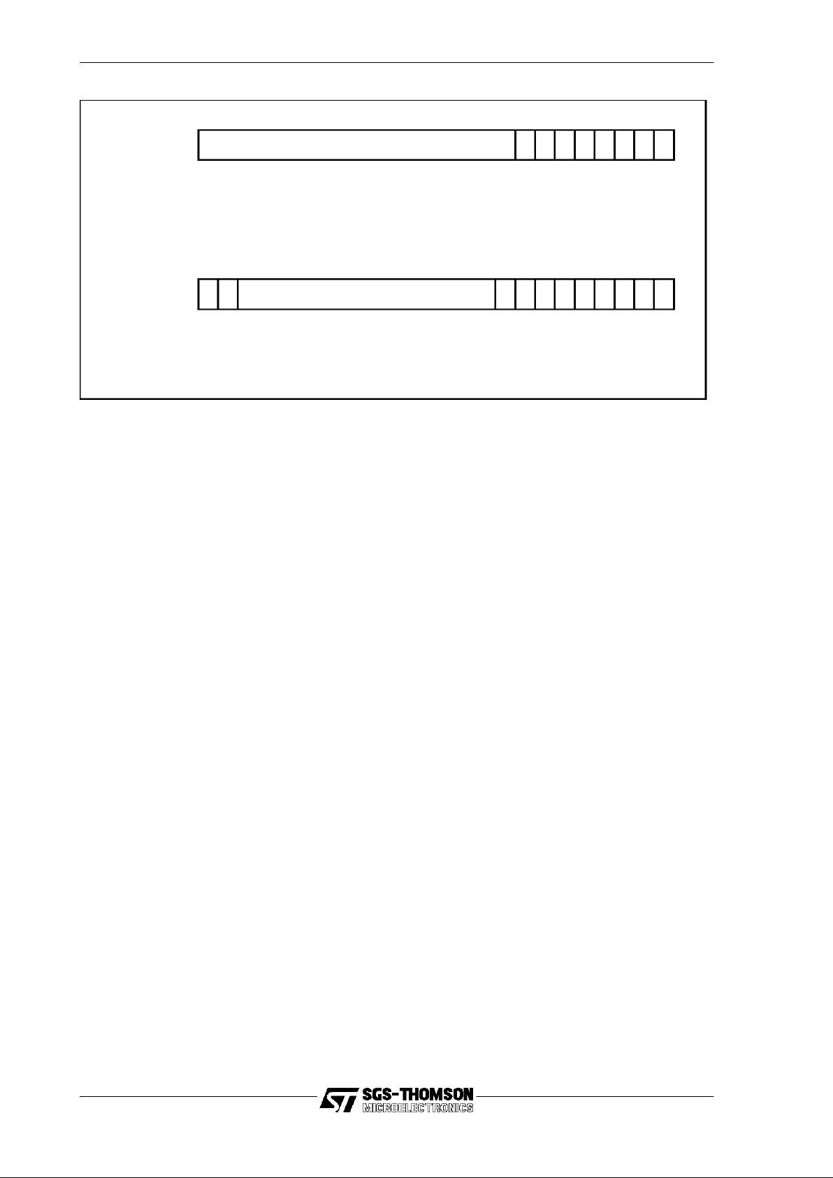
Figure 3.1 shows the ordering of bytes in words for the ST20.

17/205
3 Architecture
Figure 3.1 Bytes and bits in words
Forexample, the most significantbit of a word is bit 31, and the most significantbyte is
byte 3, consisting of bits 24 to 31. This ordering is compatible with Intel processors,
but not Motorola or SPARC.
For compatibility with other devices, a
swap32
instruction is provided to reverse the
order of byteswithin a word.
3.1.2 Signed integers and sign extension
A signed object is stored in twos-complement format. A signed value may be represented by an object of any size. Most commonly a signed integer is represented bya
single word, but as explained,it may be stored, for example,in a 64-bit object, a 16-bit
object, or an 8-bit object. In each of these formats, all the bits within the object contain
useful information.
The length of the object that stores a signed valuecan be increased, so that the object
size is increased without changing the value that is represented. This operation is
known as
sign extension
. All the extra bits that are allocated for the larger object, are
meaningful to the value of the signed integer; they must therefore be set to the appropriate value. The value for all these extra bits is the same as the value of the most
significantbit - i.e. the sign bit - of the smaller object. The ST20-C1 providesinstructions that sign extendbyte and half-word objects to words.
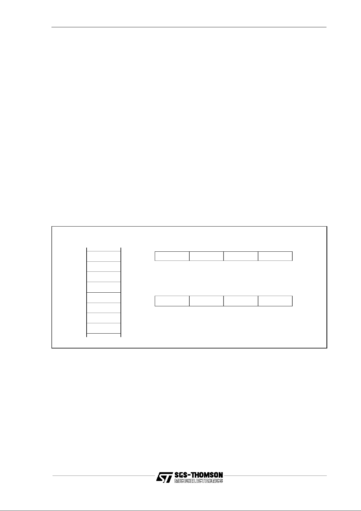
The example shown in Figure 3.2 shows how the value -10 is stored in a 32-bit
register, either as an 8-bit object or as a 32-bit object. In this case, bits 31 to 8 are
meaningful for the 32-bit object but not for the 8-bit object. These bits are set to 1 in
the 32-bit object.
3
210
Bytes in a word
Most
significant
Least
significant
Bits in a word
Most
significant
Least
significant
31
0
3.2 Memory
18/205
Figure 3.2 Storing a signed integer in different length objects
3.2 Memory
The ST20 processor is a 32-bit word machine, with byte addressing and a 4 Gbyte
address space. This section explainshow data is arranged in that address space.The
address of an object is the address of the base,i.e. the byte with the lowest address.
3.2.1 Word address and byte selector
A machine address, or pointer, is a single word of data which identifies a byte in
memory - i.e. a byte address. It comprises two parts, a word address and a byte
selector.The byte selector occupies the two least significantbits of the word; the word
address the thirty most significant bits.
An address is treated asa signed value,the range of which starts at the most negative
integer and continues, through zero, to the most positive integer. This enables the
standard arithmetic and comparison functions to be used on pointer values in the
same way that theyare used on numerical values.
Certain values can never be used as pointers because they represent reserved
addresses at the bottom of memory space. They are reserved for use by the
processor and initialization. A full list of names and values of constants used in this
manual is givenin Appendix A.
In particular, the null process pointer (known as
NotProcess
) has the value
MostNeg
,
since zero could be a valid process address.
3.2.2 Alignment
A data object is said to be
word-aligned
if it is at an address with a byte selector of
zero,i.e. the fulladdress of the object is divisibleby 4. Similarly,a data object is said to
11110110these bit values not related to integer value
07831bit position
11110110
07831bit position
11 1...
signed integervalue (-10) storedas an 8-bitobject (byte)
signed integer value(-10) stored as a32-bit object(word)
19/205
3 Architecture
be
half-word-aligned
if it is at an address with an even byte selector, i.e. the full
address of the object is divisible by 2.
Word objects, including addresses, are normally stored word-aligned in memory.This
is usually desirable to make the best use of any 32-bit wide memory. Also most
instructions that involve fetching data from or storing data into memory, use word
aligned addresses and load or store four contiguous bytes.
However, there are some instructions that can manipulate part of a word. A half-word
object is normally half-word-aligned, so it can be stored either in the least significant
16 bits of a word or in the most significant 16 bits. A data item that is represented in
two contiguous words is called a
double word
object and is normally word-aligned.
3.2.3 Ordering of information in memory
Data is stored in memory using the little-endian rule. Objects consisting of more than
one byte are stored in consecutive bytes, with the least significant byte at the lowest
address and the most significant at the highest address.
Figure 3.3 shows the ordering of bytes in words in memory. If X is a word-aligned
address then the word at X consists of the bytes at addresses X to X+3, where the
byte at X is the least significantbyte and thebyte at X+3 is the most significant byte of
the word.
Figure 3.3 Bytes in wordsin memory
3.2.4 Work space
The ST20-C1 uses a stack-based data structure in memory to hold the local working
data of a program, called the work space. The work space is a word-aligned collection
of 32-bit words pointed to by the work space pointer register (Wptr).
The programmer’s model isthat all local data is held in the work space, i.e.in memory,
and must be brought into the evaluation stack to be operated on, and then written
back from the evaluationstack to the work space.
X+7
X+6
X+5
X+4
X+3
X+2
X+1
X+0
Memory
(bytes)
X+3 X+2 X+1 X+0
MSB LSB
31 24 23 16 15 8 7 0
X+7 X+6 X+5 X+4
MSB LSB
31 24 23 16 15 8 7 0
32-bit words
X
is a word-aligned byte address
X+n
is the bytenbytes past
X
3.3 Registers
20/205
An implementation of the ST20-C1 core may include a
register cache
. This providesa
mechanism to accelerate access to local work space without changing the
programmer’smodel of how the work space operates or impacting either the excellent
code density or low interrupt latency associated with a stack-based instruction set.
3.3 Registers
This section introduces the ST20-C1 core registers that are visible to the programmer.
Seven registers, known as process state registers, define the local state of the
executing process. These registers are preserved through exceptions. One other
register is provided for performing input/output, and is not preserved through exceptions. All registers are 32-bit. Each instruction explicitly refers to specific registers, as
described in the instruction definitions.
The state of an executing process at any instant is defined by the contents of the
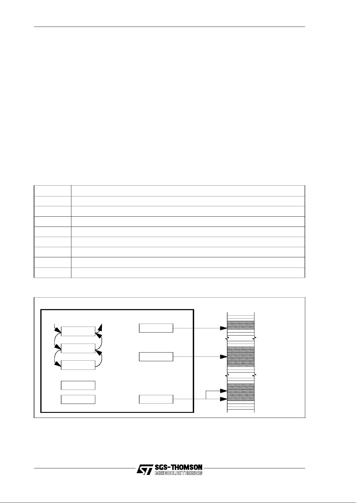
machine registers listed in Table 3.1. The registers are illustrated in Figure 3.4 and
described in the rest of this section.
Figure 3.4 Register set
Register Description
Areg Evaluation stack register A
Breg Evaluation stack register B
Creg Evaluation stack register C
Iptr Instruction pointer register, pointing to the next instruction to be executed
Status Status register
Wptr Work space pointer, pointing to the stack of the currently executingprocess
Tdesc Task descriptor
IOreg Input and output register
Table 3.1 Processor registers
Iptr
Areg
Breg
Creg
IOReg
Tdesc
Wptr
Evaluation Stack
Memory
Program
Code
Local
Program
Data
offset
base
Status
Task Descriptor
Instruction Pointer
Workspace Pointer
ST20-C1 Core
Task Control
Block

21/205
3 Architecture
3.3.1 Evaluation stack
The registers Areg, Breg and Creg are organized as a three register evaluationstack,
with Areg at the top. The evaluation stack is used for expression evaluation and to
hold operands and results of instructions. Generally, instructions maypop values from
or push values onto the evaluation stack or both, and do not address individual evaluation stack registers.
Pushing a value onto the stack means that the value initially in Breg is pushed into
Creg, the value in Areg is pushed into Breg and the new value is put in Areg.
Popping a value from the stack means that a value is taken from Areg, the value
initially in Breg is popped into Areg, and the value in Creg is popped into Breg.The
value left in Creg varies between instructions, but is generally the value initially in the
Areg. These actions are illustrated in Figure 3.5 and Figure 3.6.
Figure 3.5 Pushing a value x onto the evaluationstack
Figure 3.6 Poppinga valuefrom the evaluation stack
3.3.2 Status register
The status register contains status bits which describe the current state of the
executing process and any errors which may have been detected. Initially the status
register is set to the value given in Table7.3.
The contents of the status register are summarizedin Table 3.2 and described in more
detail in the following paragraphs. Generally the status register is local except for the
Before
Areg
Breg
Creg
After
a
b
c
a
b
x
Before
Areg
Breg
Creg
After
a
b
c
c
a
b

3.3 Registers
22/205
global interrupt enable and timeslice enable, which are global and carried from one
process to another across a context switch.
• The mac_count, mac_buffer, mac_scale and mac_mode fields are used by
the multiply-accumulate instructions to hold initialization data which must be
saved when an exception occurs. See Chapter 5 for details of multiply accumulation.
• The global_interrupt_enable bit enables external interrupts. Interrupts
remain enabled or disabled until explicitly disabled or enabledagain. This bit is
global and is maintained when a process is descheduled.
• The local_interrupt_enable enables external interrupts. Clearing this bit dis-
ables external interrupts until the current process is descheduled. This is
needed when a process delegates part of its processing to a peripheral and
then deschedules until completion, as describedin section 4.11.3.
• Overflow, underflow and carry bits relating to arithmetic state are kept in the
status word.
The ST20-C1 maintains “sticky”bits in the status word which indicate whether
an overflow or underflow has occurred. This allows a complete expression to
be evaluated before testing whether an overflow has occurred. Overflow and
underflow are chosen as they apply both to addition as well as multiply as
opposed to a more traditional method of replicating two bits out of the carry
Bit numbers Full name Meaning when set or meaning of value
0-7 mac_count Multiply-accumulate number of steps.
8-10 mac_buffer Multiply-accumulate data buffersize code.
11 - 12 mac_scale Multiply-accumulate scaling code.
13 mac_mode Multiply-accumulate accumulator format code.
14 global_interrupt_enable Enable external interrupts until explicitlydisabled.
15 local_interrupt_enable Enable external interrupts. Clearing this bit disables inter-
rupts until the current process is descheduled.
16 overflow An arithmetic operation gave a positive overflow.
17 underflow An arithmetic operation gave a negative overflow.
18 carry An arithmetic operation produced a carry.
19 user_mode A user process is executing.
20 interrupt_mode An interrupt handler is executingor trapped.
21 trap_mode A trap handler is executing.
22 sleep The processor is due to go to sleep.
23 reserved Reserved.
24 start_next_task The CPU must start executing a new process.
25 timeslice_enable Timeslicing is enabled.
26 - 31 timeslice_count Timeslice counter.
Table 3.2 Status register bits

23/205
3 Architecture
chain. In addition, they allow for saturated arithmetic to be implemented relatively easily.
A (non-sticky) carry bit is provided to allow efficient implementation of long
addition and subtraction. The carry bit is only manipulated by the
addc
and
subc
instructions allowing the other add instructions to be used in address formation of multi-word values where carry propagation is required so that the
carry is not lost in the address formation evaluations.
• The user_mode bit indicates when the machine is handling a user process,
i.e. a process which is not an exception handler. The interrupt_mode bit indicates when the machine is handling an interrupt, or a trap from an interrupt
handler and the trap_mode bit indicates when the machine is executinga trap
handler.An operating system mayneed to distinguish betweenmodes to allow
it to perform scheduling activities from a trap handler. These bits are also
required to enable the
eret
instruction to determine whether a signal to the
interrupt controller is required.
• The sleep bit indicates that the CPU is due to go to sleep, i.e. to turn off its
clocks and go into lowpower mode. This bit is set when the CPU detects there
is no user process to execute and is cleared when the CPU goes to sleep.
• The start_next_task bit when set causes the processor to attempt to run the
next process from the scheduling queue.
• The timeslice_enable bit and timeslice_count field are used for timeslicing,
as described in section 7.4.
The instructions to use the status register are described in section 4.12.
3.3.3 The work space pointer
All programs need somewhere to store local working data, e.g. local variables in the
application code. In the ST20 architecture, this local storage is termed the
work space
of the program.
The Wptr register is the local work space pointer,which holds the address of the stack
of the executing process. The stack is downward pointing, so space is allocated by
moving the Wptr to a lower address. This address is word aligned and therefore has
the two least significant bits set to zero. When a process is descheduled, the Wptr is
stored as part of the process descriptor block, which is pointed to by Tdesc.
The Wptr is used as a base for addressing
local
variables. A word offset from the
Wptr is the operand for the instructions
ldl
(load local),
stl
(store local) and
ldlp
(load
local pointer).
The ST20-C1 simplifiesthe normal stack scheme by decoupling the load/store action
from the pointer update:
• Load-local and store-local instructions access values in the work space with
addresses relative to the Wptr, but do not change the valueof Wptr.
• Separate instructions (
ajw,gajw
) are provided to update the work space

3.4 Instruction encoding
24/205
pointer by any amount in one step without needing a series of increments or
decrements.
On calling a function or procedure,the Wptr is normally decreased to a loweraddress
to allocate space for the parameters and local variables of the function. This is
performed using the instruction
ajw
. The Wptr is returned to its initial value before
returning from the function to free the local workspace.
3.3.4 The task descriptor
The task descriptor Tdesc points to the process descriptor block for the currently
executing process. The value held in the Tdesc becomes the process identifierwhen
the process is not executing.
The process descriptor block is a block of memory whose contents depend on the
state of the process. It will generally hold the saved Wptr and Iptr for the process, and
may hold a link to the next process if the process is in a queue of waiting processes.
The process descriptor block is described in section 7.2.
3.3.5 IO register
The bits of the IOreg are mapped to external connections on the ST20-C1 core.They
may be used to signal to, or read signals from, peripherals on or off chip. The
io
instruction is used to read and write to the IOreg and is described in section 4.11. The
IOreg is global, and remains unchanged by any context switch. The bits of the IOreg
are definedin Table 3.3.
In some ST20 variants, some bits of the IO register may be reserved for system use.
The reserved bits will be the most significant bits of the appropriate half word. The
number of any such bits is given in the data sheet for each variant.
3.4 Instruction encoding
The ST20-C1 is a zero-address machine. Instruction operands are alwaysimplicit and
no bits are needed in the instruction representation to carry address or operand
location information. This results in very short instructions and exceptionallyhigh code
density.
The instruction encoding is designed so that the mostcommonly executed instructions
occupy the least number of bytes. This reduces the size of the code, which saves
memory and reduces the memory bandwidth needed for instruction fetching. This
section describes the encoding mechanism.
A sequence of single byte
instruction components
is used to encode an instruction.
The ST20 interprets this sequence at the instruction fetch stage of execution. Most
Bits Purpose
0-15 Output data
16-31 Input data
Table 3.3 IOreg bits
25/205
3 Architecture
programmers, working at the level of microprocessor assembly language or high-level
language, need not be aware of the existence of instruction components and do not
generally need to consider the encoding.
This section has been included to provide a background. Appendix C discusses
consequential issues which need to be considered in order to implement a code
generator.
3.4.1 An instruction component
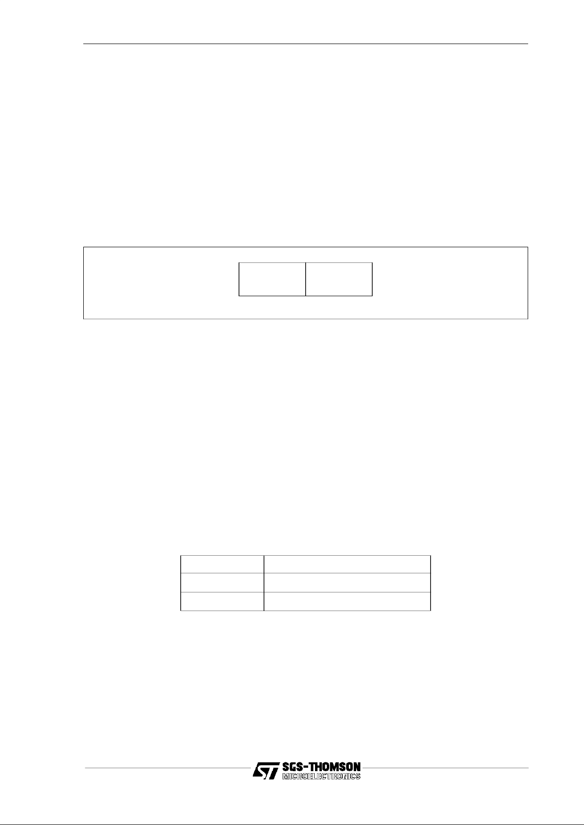
Each instruction component is one byte long, and is divided into two 4-bit parts. The
four most significant bits of the byte form a
function code
, and the four least significant
bits are used to build an
instruction data value
as shown in Figure 3.7.
Figure 3.7 Instruction format
This representation provides for sixteen function code values (one for each function),
each with a data field ranging from 0 to 15.
Instructions that specify the instruction directly in the function code are called
primary
instructions
or
functions
. There are 13 primary instructions, and the other three
possible function code values are used to build larger data values and other instructions. Two function code values,
pfix
and
nfix
, are used to extend the instruction data
value by prefixing. One function code
operate(opr
) is used to specify an instruction
indirectly using the
instruction data value.opr
is used to implement
secondaryinstruc-
tionsoroperations
.
3.4.2 The instruction data value and prefixing
The data fieldof an instruction component is used to create an instruction data value.
Primary instructions interpret the instruction data value as the operand of the instruction. Secondaryinstructions interpret it as theoperation code for the instruction itself.
The instruction data value is a signed integer that is represented as a 32-bit word. For
each new instruction sequence, the initial value of this integer is zero.Since there are
only 4 bits in the data field of a single instruction component, it is only possible for
most instruction components to initially assign an instruction data value in the range 0
to 15. Prefix components are used to extend the range of the instruction data value.
mnemonic name
pfix
n
prefix
nfix
n
negative prefix
Table 3.4 Prefixinginstruction components
function code data
0347

3.4 Instruction encoding
26/205
One or more prefixing components may be needed to create the full instruction data
value. The prefixes are shown in Table3.4 and explained below.
All instruction components initially load the four data bits into the least significant four
bits of the instruction data value.
pfix
loads its four data bits into the instruction data value,and then shifts this value up
four places. Consequently,a sequence of one or more prefixes can be used to extend
the data valueof the following instruction to any positive value. Instruction data values
in the range 16 to 255 can be represented using one
pfix
.
nfix
is similar,except that it complements all 32 bits of the instruction data value before
shifting it up, thus changing the sign of the instruction data value. Consequently, a
sequence of one or more
pfix
es with one
nfix
can be used to extend the data value of
a following instruction to any negative value. Instruction data values in the range -256
to -1 can be represented using one
nfix
.
When the processor encounters an instruction component other than
pfix
or
nfix
,it
loads the 4-bit data field into the instruction data value. The instruction encoding is
now complete and the instruction can be executed. The instruction data valueis then
cleared so that the processor is ready to fetch the next instruction component, by
building a new instruction data value.
For example, to load the constant 0x11, the instruction
ldc
0x11 is encoded with the
sequence:
pfix1;ldc
1
The instruction
ldc
0x2A68 is encoded with the sequence:
pfix2;pfixA;pfix6;ldc
8
The instruction
ldc
-1 is encoded with the sequence:
nfix0;ldc
F
3.4.3 Primary Instructions
Research has shown that computers spend most time executing a small number of
instructions such as:
• instructions to load and store from a small number of ‘local’ variables;
• instructions to add and compare with small constants; and
• instructions to jump to or call other parts of the program.
For efficiency, in the ST20 these are encoded directly as primary instructions using
the function field of an instruction component.
Thirteen of the instruction components are used to encode the most important operations performed by any computer executing a high levellanguage. These are used (in
conjunction with zero or more prefixes) to implement the primary instructions. Primary
instructions interpret the instruction data value as an operand for the instruction. The
mnemonic for a primary instruction always includes this operand, shown in this
manual asn.

27/205
3 Architecture
The mnemonics and names for the primary instructions are listed in Table 3.5.
3.4.4 Secondary instructions
The ST20 encodes all other instructions, known as
secondary instructions,
indirectly
using the instruction data value.
The function code
opr
causes the instruction data value to be interpreted as the
operation code of the instruction to be executed. This selects an operation to be
performed on the values held in the evaluation stack, so that a further 16 operations
can be encoded in a single byte instruction. The
pfix
instruction component can be
used to extend the instruction data value, allowing any number of operations to be
encoded.
Secondary instructions do not have an operand specified by the encoding, because
the instruction data value has been used to specify the operation.
To ensure that programs are represented as compactly as possible,the operations are
encoded in such a way that the most frequently used secondary instructions are
represented without using prefix instructions.
Forexample, the instruction
add
is encoded by:
opr
4
The instruction
and
is encoded by:
opr
F9
mnemonic name
adc n
add constant
ajw n
adjust work space
fcall n
function call
cj n
conditional jump
eqc n
equals constant
jn
jump
ldc n
load constant
ldl n
load local
ldlp n
load local pointer
ldnl n
load non-local
ldnlp n
load non-local pointer
stl n
store local
stnl n
store non-local
Table 3.5 Primary instructions
mnemonic name
opr n
operate
Table 3.6 Operate instruction

3.4 Instruction encoding
28/205
which is in turn encoded with the sequence:
pfixF;opr
9
3.4.5 Summary of encoding
The encoding mechanism has important consequences.
• It produces very compact code.
• It simplifies language compilation, by providing a completely uniform way of
allowing a primary instruction to take an operand of any size up to the processor word-length.
• It allows these operands to be represented in a form independent of the wordlength of the processor.
• It enables any number of secondary instructions to be implemented.
To aid clarity and brevity,prefix sequences and the use of
opr
are not explicitly shown
in this guide. Each instruction is represented bya mnemonic, and for primary instructions an item of data, which stands for the appropriate instruction component
sequence. Hence the examples above would be just shown as:
ldc 17,add
, and
and
.
Where appropriate, an expressionmaybe placed in a code sequence to represent the
code needed to evaluatethat expression.

29/205
3 Architecture
4.1 Manipulating the evaluation stack
30/205
4 Using ST20-C1 instructions
This chapter describes the purpose for which the sequential instructions are intended,
except for the multiply-accumulate instructions, which are described in Chapter 5.
These instructions are described in the context of their intended use. Some instructions are designed for use in a particular sequence of instructions, so this chapter
describes those sequences. Instructions for exceptions are described in Chapter 6
and multi-tasking instructions are described in Chapter 7.
The architecture of the ST20-C1, including the registers and memory arrangement, is
described in Chapter 3.
4.1 Manipulating the evaluation stack
The evaluation stack consists of the registers Areg, Breg and Creg. The general
action of the evaluationstack is described in section 3.3.1.
Instructions are provided for shuffling and re-ordering the values on the evaluation
stack, as listed in Table4.1.
rot
pops the value from Areg off the evaluationstack and rotates it into Creg, and
arot
pushes the value from Creg onto the stack.
rev
swaps the Areg and Breg, and
dup
pushes a copy of Areg onto the stack.
Table 4.2 shows how each of these affects the evaluation stack. Each row shows the
contents of the evaluation stack after one of these instructions is executedif the initial
values of the Areg, Breg and Creg are a, b and c respectively.
Many instructions leave the initial Areg in Creg. This value may be restored into the
Areg by using
arot
.
Mnemonic Name
rot
rotate stack
arot
anti-rotate stack
dup
duplicate stack
rev
reversestack
Table 4.1 Evaluation stack manipulation instructions
Instruction Areg Breg Creg
rot
bca
arot
cab
rev
bac
dup
aab
Table 4.2 Evaluation stack manipulation

31/205
4 Using ST20-C1 instructions
4.2 Loading and storing
The loading and storing instructions are listed in Table 4.3.
On the ST20, the term
loading
means pushing a value onto the evaluation stack. The
value to be loaded may be a value read from memory, a constant, a copy of another
register or a calculated value.
Storing
means popping a value from the evaluation
stack.The valuemaybe written into memory or written into another register. The evaluation stack is described in section 3.3, and evaluationof expressions is described in
section 4.3.
Relative addresses are used for accessing memory in order to reduce code size, as
the operand values are smaller than full machine addresses. Data structures are
word-aligned, so relative addresses can be word offsets, reducing the operand size
further.
The most common operations performed by a program are loading and storing of a
small number of variables,and loading small literal values.
4.2.1 Loading constants
One primary instruction
ldc
is provided for loading a generalconstant, for initializing a
variable or register or for a constant in an expression.
4.2.2 Local and non-local variables
When loading from and storing to memory,the ST20 distinguishes between local and
non-local addressing. Local addressing means that the address is given as a word
offset from the Wptr. Non-local addressing means that the address is givenas a word
offset from the Areg. In practice, the Wptr points to the stack, so local addressing is
Mnemonic Name Description
ldc n
load constant Load the constantn.
ldl n
load local
Load the value fromnwords above Wptr.
stl n
store local
Store a value tonwords above Wptr.
ldnl n
load non-local
Load the value fromnwords above Areg.
stnl n
store non-local
Store a value tonwords above Areg.
lbinc
load byte and increment Load a byte and increment the address by 1 byte.
sbinc
store byte and increment Store a byte and increment the address by 1 byte.
lsinc
load sixteen and increment Load a half word and increment the address by 2 bytes.
lsxinc
load sixteen sign extended
and increment
Load ahalf wordandsign extendto 32 bitsand increment
the address by 2 bytes.
ssinc
store sixteen and increment Store a half word and increment the address by 2 bytes.
lwinc
load word and increment Load a word and increment the address by 4 bytes.
swinc
store word and increment Store a word and increment the address by 4 bytes.
Table 4.3 Loading and storing instructions

4.2 Loading and storing
32/205
normally used for local variables on the stack while non-local addressing is normally
used for all other variables.
The primary instructions
ldl
and
stl
perform loading and storing of local variables. For
exampleto loada valuexwords above the Wptr and write to a locationywords above
the Wptr:
ldl x;
stl y;
The primary instructions
ldnl
and
stnl
perform loading and storing of non-local vari-
ables. For example, to load a valuexabove a base address
x_base
and store to a
locationywords above
y_base
, where
x_base
and
y_base
are held in local variables:
ldl x_base; ldnl x;
ldl y_base; stnl y;
Note that for the purposes of this manual,
ld X
denotes loading the value from a
variableX, whereXmay be a local or non-local variable, so either
ldlorldnl
may be
used as appropriate. Similarly
st X
denotes storing a value into a variableX, where
X
may be a local or non-local variable,so either
stlorstnl
may be used.
4.2.3 Byte and half-word values
Instructions are provided for loading and storing byte and half-word variables. In each
case, the address is initially in the Areg and is incremented by the size of the object,
so that repeated loads and stores can be used to copya block of memory.
The load instructions place the loaded value in the Areg, the incremented address in
the Creg and leave the Breg unaffected. The store instructions write the initial Breg
into memory at the address in theAreg, leaving the incremented address in the Breg,
the initial Creg in the Areg and the initial Breg pushed down to the Creg.
Byte loading and storing
lbinc
loads the byte at the address in Areg, into the evaluation stack.
lbinc
replaces
the address in Areg with the byte stored at that address, treating it as an unsigned
integer by setting the twenty-four most significantbits in Areg to 0. The incremented
address is left in Creg.
sbinc
writes the least significant byte in Breg to the location addressed by Areg. The
address is incremented by 1 and put in the Breg.
Half-word loading and storing
lsinc
and
lsxinc
load the half-word object at the address in Areg, into the evaluation
stack.
lsinc
replaces the address in Areg with the half word, treating it as an unsigned
integer by setting the sixteenmost significantbits in Areg to 0.
lsxinc
is similar to
lsinc
,
but treats the half-word as a signed integer in twos-complement format, and hence
sign extends the representation by setting the sixteen most significant bits in Areg to
the same value as the most significant bit of the half-word object. Sign extension is
discussed in section 4.4.6.

33/205
4 Using ST20-C1 instructions
ssinc
writes the half word in the two least significant bytes of Breg to the location
addressed by Areg.
4.2.4 Memory block copy
A block memory copy may be implemented using the instructions
lwinc
and
swinc
.
These instructions load or store a word, and increment the addresses used.
To copynbytes from
sourcetodestination
, where
source
and
destination
are both
word-aligned, a loop should be written, using the temporary variable
limit
, as in the
following code:
ld source; ld n; ld destination
add; stl limit
LOOP: lwinc; rev; swinc
ldl limit; arot
gt; cj END; j LOOP;
END:
This is the most efficient method of copying, since it reads and writes full words,
making the best use of any 32-bit memory.However, this is not alwayspossible if the
alignment of the source and destination blocks are different. In that case the byte or
half-word load and store should be used.
4.3 Expression evaluation
Expression evaluation and address calculation is performed using the evaluation
stack. For example, the evaluation of operations with two integer operands is
performed by instructions that operate on the values of Areg and Breg. The result is
left in Areg.
Arithmetic and boolean calculations are considered in sections 4.4 and 4.7 respectively. This section describes how the evaluation stack is used. Loading and storing
instructions are described in section 4.2.
In this and subsequent sections,in examples of assemblycode, a single letter or identifier written as an instruction is either an expression or a segment of code. If it is an
expression then it means ‘evaluate the expression and leave the result in theAreg.
4.3.1 Using the evaluation stack
A compiler normally loads a constant expressioncusing
ldc
:
ldc c
Loading from a constant tableis described in section 4.3.3.
An expression consisting of a single local variable is loaded using
ldl x
Methods for loading non-local variables are discussed in section 4.2, and array
elements in section 4.5.

4.3 Expression evaluation
34/205
Evaluation of expressions sometimes requires the use of temporary variables in the
process work space, but the number of these can be minimized by careful choice of
the evaluationorder.The details of howthis is achievedby a compiler are described in
Appendix C in section C.3.
4.3.2 Loading operands
The three registers of the evaluation stack are used to hold operands of instructions.
Evaluation of an operand or parameter may involve the use of more than one register.
Care is needed when evaluating such operands to ensure that the first operand to be
loaded is not pushed off the bottom of the evaluationstack by the evaluation of later
operands. The processor does not detect evaluationstack overflow.
Three registers are availablefor loading the firstoperand, two registers for the second
and one for the third. Consequently,the instructions are designed so that Creg holds
the operand which, on average,is the most complex, and Areg the operand which is
the least complex.
In some cases, it is necessary to evaluate the Areg and Breg operands in advance,
and to store the results in temporary variables. This can sometimes be avoided using
the reverse instruction. Any of the following sequences may be used to load the
operandsA,BandCinto Areg, Breg and Creg respectively.
1C;B;A;
2 C; A; B; rev;
3 B; C; rev; A;
4 A; C; rev; B; rev;
The choice of loading sequence, and of which operands should be evaluated in
advance is determined by the number of registers required to evaluate each of the
operands. The algorithm used bycompilers is givenin Appendix C in section C.4.
4.3.3 Tables of constants
The ST20-C1 instruction set has been optimized so that the loading of small constants
can be coded compactly — for example it allows the loading of constants between 0
and 15 to be coded in a single byte. Analysis of programs shows that such small
constants occur markedly more frequently than large constants. However when a
large constant does need to be loaded the necessary prefix sequence may be long.
Other techniques maybe more efficientin these cases.
A simple mechanism to increase the code compactness is to use a tableof constants.
This is implemented by storing all the long constants into a look-up table. This table
and all its constant entries must be aligned on a word boundary. The address of this
table is held in a local variable which is used to index the array. Then to load the

35/205
4 Using ST20-C1 instructions
constant from thenth entry in the constant table stored at address
constants_ptr
the
following code wouldbe used:
ldl constants_ptr;ldnl n;
where the instruction
ldnl n
is explained in section 4.2.2.
This code sequence only takes 2 bytes, provided
constants_ptr
is less than 16 words
from the work space pointer address and there are no more than 16 word-length
constants. At worse it is unlikely to take more than 4 bytes.Hence, if a constant takes
4 or more bytes to load using
ldc
then this sequence often improves code compact-
ness — especially if the constant is used more than once.
4.3.4 Assignment
Single words, half words and bytes may be assigned using the load and store instructions described in section 4.2.
Word assignment
Ifxandyare both single word variables andeis a word valued expression then word
assignments are compiled as
x = y
compiles to
ld y; st x;
x = e
compiles to
e; st x;
Byte assignment
Ifaandbare both single byte variables andeis a byte valued expression then byte
assignments are compiled as
b = a
compiles to
address(a); lbinc; address(b); sbinc;
b = e
compiles to
e; address(b); sbinc;
where
address(variable)
is the address of variable. Forming addresses is discussed in
section 4.5.
Half word assignment
Ifaandbare both half-word variables andeis a half-word valued expression then
half-word assignments are compiled as
b = a
compiles to
address(a); lsinc; address(b); ssinc;
b = e
compiles to
e; address(b); ssinc;
where
address(variable)
is the address of variable. Forming addresses is discussed in
section 4.5.
4.4 Arithmetic
This section describes the use of the arithmetic instructions except for the multiplyaccumulate instructions, which are described in Chapter 5, and forming addresses,
which is described in section 4.5. Boolean expression evaluation is discussed in

4.4 Arithmetic
36/205
section 4.7, and the general principles of expression evaluation are described in
section 4.3.
4.4.1 Addition, subtraction and multiplication
Single length signed arithmetic is provided by the operations listed in Table 4.4.
Each of these instructions except
smul
can signal
overfloworunderflow
by setting the
appropriate bit in the status register. An overflow occurs if the result is greater than
MostPos
and an underflowif it is less than
MostNeg
. If overflow or underflow occurs,
then the 32 least significant bits of the full result are left in the Areg. The overflow and
underfloware ‘sticky’, so when one has been set, it is not cleared and the other cannot
be set by subsequent arithmetic. The overflow and underflow bits may be used for
saturated arithmetic, as described in section 4.4.3.
The primary instruction
adc n
adds the constant valuento Areg. Breg and Creg are
unaffected. This is used for incrementing and decrementing variablesand counters.
Ifopis one of
add,sub,mulorsmul
, then the instruction sequence
ldl X; ldl Y;op;
evaluates the expression
XopY
i.e. it takes the value in Breg as the left hand operand and the value in Areg as the
right hand operand, and loads the result into Areg. The content of Creg is popped into
Breg and the initial Areg is rotated into Creg.
smul
multiples two half-word values producing a 32-bit result. It cannot overflow or
underflow and is faster than
mul
.
4.4.2 Division and remainder
Division and remainder are performed using the operations listed in Table 4.5.
Mnemonic Name
adc n
add constant
add
add
sub
subtract
mul
multiply
smul
short multiply
Table 4.4 Single length signed integer arithmetic instructions
Mnemonic Name
divstep
divide step
unsign
unsign argument
Table 4.5 Division and remainder instructions

37/205
4 Using ST20-C1 instructions
Each
divstep
generates four bits of the unsigned quotient, so eight
divstep
s are
needed for a full 32-bit unsigned division, and will also generate a remainder. The
result of the division is the integer division rounded towards zero (truncated). The
quotient is left in Breg, andthe remainder in Creg, so a rotation pops the quotient into
the Areg.
unsign
is used to separate the sign from the magnitude of the operands before
performing the division. Division is then performed on the magnitudes, and the signs
of the results maybe derived from the signs of the operands.
Overflow can occur only if the divisor (Areg) is zero, or if the dividend (Breg)is
MostNeg
and the divisor is -1.
divstep
does not detect these cases, and does not set
any status bits, so a check should be applied beforeperforming the division.
The following code sequence performs the integer division
a/b
. The signed quotient is
left in Areg.
a; b; ldc 0; arot; unsign;
arot; unsign; cj POS;
ldc 0; rot;
divstep; divstep; divstep; divstep;
divstep; divstep; divstep; divstep;
rot; not; adc 1;
j END;
POS: rot;
divstep; divstep; divstep; divstep;
divstep; divstep; divstep; divstep;
rot;
END:
The following code sequence performs the remainderaremb. The signed remainder
is left in Areg.
a; b; ldc 0; rev; unsign;
eqc 2; arot; unsign; cj POS;
divstep; divstep; divstep; divstep;
divstep; divstep; divstep; divstep;
arot; not; adc 1;
j END;
POS: rot;
divstep; divstep; divstep; divstep;
divstep; divstep; divstep; divstep;
arot;
END:
4.4.3 Saturated arithmetic
In saturated arithmetic, when an overflow or underflow occurs the result is set to the
most positive or most negative possible result respectively,instead of the least significant bits of the full result. This ensures that the result is as near as possibleto the real
value and preventsglitches caused bywrap-around.

4.4 Arithmetic
38/205
Saturated arithmetic is achieved on the ST20-C1 by evaluating an expression and
then performing the
saturate
instruction. If an overflow or underflowhas occurred then
the corresponding status bit will have been set, which will cause saturate to change
the value in Areg to the most positive or most negative value respectively.
saturate
clears the overflow and underflow bits.
For example,to perform a saturated multiply ofaandb:
ld a; ld b;
mul; saturate;
4.4.4 Unary minus
The expression
(-e)
can be evaluatedwith overflow signalling by:
e; not; adc 1;
or
ldc 0; e; sub;
The first sequence ,using
not
, requires one less stack register than the second.
not
is
a bitwise inversionwhich is described in section 4.8.
4.4.5 Long arithmetic
The long arithmetic instructions are listed in Table 4.6.
Multiple length addition and subtraction
Multiple length addition or subtraction are performed using
addc
and
subc
, executed
once for each word of the result. Forboth instructions, the carry (or borrow) is held in
the carry bit of the status register. This keeps the carrying separate from overflow,so
address calculations may be safely performed using
add,sub
and
wsub
without
affecting the carry.
The
addc
instruction forms (Breg + Areg)+Status
carry
leaving the least significant
word of the result in Areg and the most significant (carry) bit in the carry bit of the
status register. The Areg is rotated into the Creg.
Similarly, the
subc
instruction forms (Breg - Areg)-Status
carry
leaving the least
significant word of the result in Areg and the borrow bit in the carry bit of the status
register. The Areg is rotated into the Creg.
Addition of two double length unsigned values,XandY, givingZ, without overflow
signalling can thereforebe compiled as follows
Mnemonic Name
addc
add with carry
subc
subtract with carry
umac
unsigned multiply accumulate
Table 4.6 Long arithmetic instructions

39/205
4 Using ST20-C1 instructions
ldc 0;
ldl Xlo; ldl Ylo; addc; stl Zlo;
ldl Xhi; ldl Yhi; addc; stl Z
hi
The subscripts ‘lo’ and ‘hi’, used here and in subsequent text, specify the least and
most significant word respectively of the double word variable with which they are
associated.
Subtraction of two double length values,YfromXgivingZ, without overflowsignalling
is compiled as
ldc 0;
ldl Xlo; ldl Ylo; subc; stl Zlo;
ldl Xhi; ldl Yhi; subc; stl Z
hi
Overflow signalling for signed arithmetic may be added by performing an extra
addc
or
subc
to produce a final word which contains only a sign (0 for positive or -1 for
negative) unless an overflow has occurred. For example, the following code could be
used to perform doublelength signed addition with overflow signalling:
clear carry, overflow and underflowstatus bits
ld X
lo;
ld Y
lo;
addc; st Z
lo;
ld X
hi;
ld Y
hi;
addc; st Z
hi;
ldc 0; dup; addc;
dup; adc #7ffffff; - overflows if and only if carry word > 0
rev; adc #8000001; - underflowsif and only if carry word < -1
Multiple length multiplication
The
umac
instruction multiplies two single word unsigned operands in Areg and Breg,
and adds the single word carry operand in Creg to form a double length unsigned
result. The more significant(carry) word of the result is left in Breg, the less significant
in Areg. No overflowcan be signalled by this instruction.
Multiplication of a single length unsigned valueXby a double length unsigned value
Y
(leaving the ‘carry’ in Areg) can be performed by:
ldc 0;
ldl X; ldl Ylo; umac; stl Zlo;
ldl X; ldl Yhi; umac; stl Z
hi
Double length unsigned multiplication is more complex. The product of two unsigned
double length wordsXandYcan be expressed as:
X*Y=(Xhi*232+Xlo)*(Yhi*232+Ylo)
=(Xhi*Yhi)*264+(Xhi*Ylo+Xlo*Yhi)*232+(Xlo*Ylo)
This can be coded as follows:
ldc 0;
ldl Xlo; ldl Ylo; umac; stl Z
0
ldl Xlo; ldl Yhi; umac; rev;stl Z
2

4.4 Arithmetic
40/205
ldl Xhi; ldl Ylo; umac; stl Z1;
ldl Xhi; ldl Yhi; umac; rev;stl Z3;
ldc 0; rev; ldl Z2; addc; stl Z2;
ldl Z3; addc; stl Z
3
This gives a quadruple length unsigned resultZ, where
Z
0
is the least significant and
Z
3
the most significant word ofZ.
4.4.6 Object length conversion
Object length conversion operations are provided by the instructions listed in Table
4.7.
Section 3.1 explains that data can be represented in data objects of various sizes.
This section describes the instructions that can be used to convert between these
representations.
Most of the ST20-C1 integer arithmetic instructions operate on signed integers held in
the evaluation stack registers as 32-bit objects, and produce results in this form.
Object length conversionis important forconversion of high levellanguage data types.
The ST20-C1 therefore provides instructions that allow a byte or half-word signed
integer to be sign extended to 32-bits by copying the sign bit to all the bits that were
previously not significant,as shown in Figure 3.2. The sign extensionis performed on
the valuein the Areg and the result is placed in the Areg. The other registers are not
affected.
xbword
extends a signed byte to a word by copying bit 7 into bits 8 to 31.
xsword
extends a signed half-word to a word by copying bit 15 into bits 16 to 31.
lsxinc
loads a sixteen bit value, sign extends it to 32 bits and increments the address
by two bytes. This is the same as:
lsinc; xsword;
Mnemonic Name
xbword
sign extend byte to word
xsword
sign extend sixteen to word
Table 4.7 Object length conversioninstructions

41/205
4 Using ST20-C1 instructions
4.5 Forming addresses
The addressing instructions provide access to items in data structures using short
sequences of single byteinstructions. These instructions are listed in Table 4.8.
4.5.1 The address of a variable
The absolute address of a local work space location is loaded using the
ldlp
primary
instruction.
ldlp
0 can be used to load the valuein the Wptr.
The
ldnlp
primary instruction is provided to calculate the absolute address of a non-
local variable.
The meaning of local and non-local is described in section 4.2.
4.5.2 The address of an instruction
The address of a location in the program being executed can be obtained by the
ldpi
operation as follows. The address of the locationxbytes past the next instruction
(which is itself pointed to by the instruction pointer register) can be pushed onto the
evaluation stack by
ldc x; ldpi
Forexample, the address of a labelLcan be loaded by
ldc (L-M); ldpi
M:
where the labelMis the address of the instruction that followsthe
ldpi
instruction. First
the offset in bytes fromMtoLis loaded into Areg. The
ldpi
then uses this offset and
the value in the instruction pointer register (which will be the address of labelM)to
load the address of labelLinto Areg. This technique is useful for generating relocatable code. Breg and Creg are unaffected.
4.5.3 Arrays
The
wsub
instruction interprets Areg as the address of the beginning of a vector of
word-sized data objects, and Breg as an index into that vector.After execution, Areg
holds the address of the indexed element, and Creg is popped into Breg, leaving
Areg rotated into Creg. The operation performed by
wsub
is to multiply the integer in
Breg by four and to add this to the address in Areg (without overflowchecking).
Mnemonic Name Meaning
ldlp n
load local pointer
Load the value Wptr +4
n
.
ldnlp n
load non-local pointer
Load the value Areg +4
n
.
ldpi n
load pointer to instruction
Load the value Iptr +
n.
wsub
word subscript
Load the value Areg +4.Breg.
Table 4.8 Addressing instructions

4.5 Forming addresses
42/205
Access to a component of an array can be split into two sections; first the address of
the component must be constructed, and then the transfer of data to or from that
component must be performed.
Evaluating a subscript
Array subscripts can be evaluatedefficiently using the
smulormul
instruction. If array
A
has been declared by
intA[
S
1
]
...[S
n
];
where
S
i
(
i = 1..n
) are the dimensions, then one way of arranging this in memory is to
have all elements of the array in a contiguous block. For the purposes of this section,
suppose that the elements in the last dimension are stored adjacently; otherwise
change the order of the dimension subscripts. For example Figure 4.1 shows the
elements of a particular three dimensional array(Array) stored in this way.
Figure 4.1 A possible method of storing an arrayof integers
If an access is required to the following array element
A[e
1
]
...[e
n
]
then the code to evaluatethe subscript is
e1;
ldc S2; mul; e2; add;
ldc S3; mul; e3; add;
...
ldc Sn; mul; en; add;
For example to evaluatethe subscript for element Array[x][y][z], (where Array
is declared as in Figure 4.1) the code sequence is
ld x;
ldc 2; mul; ld y; add;
ldc 3; mul; ld z; add;
If x is 1, y is 0 and z is 2, then this evaluates to 8, which as can be seen from Figure
4.1, is the correct offset from the base of the array.
Array[1][1][1]
Array[1][1][0]
Array[1][1][2]
Array[1][0][1]
Array[1][0][0]
Array[1][0][2]
Array[0][1][1]
Array[0][1][0]
Array[0][1][2]
Array[0][0][1]
Array[0][0][0]
Array[0][0][2]
int Array[2][2][3];
Increasing
memory
addresses
Contiguous
locations for
words in
memory
space

43/205
4 Using ST20-C1 instructions
Accessing a word addressed array
Let
Wa_ptr
be a pointer to an array
Wa
that starts at a word boundary,and in which all
component types are measured in words. Letebe a subscript expression. The
address of componenteof
Wa
is
e; Wa_ptr; wsub;
or ifeis a constant expressionthis can be optimizedto:
Wa_ptr; ldnlp e;
Accessing a byte addressed array
Similarly, let
Ba_ptr
be a pointer to an array(Ba) which maystart at any byte location,
and in which each component type is measured in bytes.Letebe a subscript expression.
The address of componenteof
Ba
is:
e; Ba_ptr; add;
4.6 Comparisons and jumps
This section describes the arithmetical comparison instructions and their use in conditional program behavior. Unconditional jumps are also described. Functions and
procedures are described in section 4.10, and evaluation of boolean expressions is
described in section 4.7.
Comparisons, conditional behavior and jumps are provided by the instructions listed in
Table 4.9.
4.6.1 Representation of true and false
The ST20 uses 0 as
false
and 1 as
true
. These values are generated by predicate
operations (for example comparisons). They can be loaded with single byte load
constant instructions.
Mnemonic Name
eqc n
equal to constant
gt
greater than
gtu
greater than unsigned
order
order
orderu
order unsigned
cj n
conditional jump
jn
jump
jab
jump absolute
Table 4.9 Comparison and jump instructions

4.6 Comparisons and jumps
44/205
Implementation of languages with different representations of
true
and
false
It is easy to implement programming languages that use a different representation of
true
and
false
. For example, using
eqc X; not; adc 1
in place of
eqc X
and
gt; not; adc 1
in place ofgt, does not affect the representation of a
false
result, but changes the
representation of
true
to -1, which is used in some programming languages.
4.6.2 Comparison
The primary instruction
eqc n
loads Areg with a truth value —
true
if Areg is initially
equal to the instruction operand (n),
false
otherwise. Breg and Creg are unaffected.
gt
and
gtu
take integer operands in Areg and Breg and produce a boolean result
which is loaded into Areg. They also load the value in Creg into Breg, saving a copy
of the initial Areg in Creg.
Thegtinstruction loads Areg with
true
if Breg > Areg,
false
otherwise, treating Areg
and Breg as signed values.Similarly
gtu
loads Areg with
true
if the
unsigned
value of
Breg is greater than the
unsigned
value of Areg;
false
otherwise.
4.6.3 Jump and conditional jump
There are tworelative jump instructions; both are primary instructions.
The unconditional jump instruction,
jn
, adds its operand (n) to the address of the
instruction immediately following it and puts the result into Iptr, thus transferring
execution to another part of the program.
The conditional jump instruction,
cj n
, performs a jump if the value in Areg is 0 and
does not affectthe evaluation stack. If the value in Areg is not 0cjrotates the valuein
Areg to the bottom of the evaluation stack and continues with the next instruction.
Consequently
cj n
serves as ‘jump if
false
’ provided that the language being imple-
mented interprets 0 as
false
(see section 4.6.1).
4.6.4 Conditional transfer of control
The conditional expressions used in a conditional branch of an if construct are
compiled using the conditional jump. The statement:
if (E){
P
}
This compiles to:
E; cj L;
P; j ENDIF;
L:

45/205
4 Using ST20-C1 instructions
where the label
ENDIF:
is at the end of the code for the if construct.
The compilation of a while loop is shown by the followingexample.
while (E){
P
}
This compiles to:
L: E; cj ENDWHILE
P; timeslice; j L
ENDWHILE:
Note that this loop includes a
timeslice
instruction. This causes the current process to
be descheduled if a timeslice is due and timeslicing is enabled. The presence of this
ensures that the process cannot occupy the CPU for too long provided timeslicing is
enabled. It is good practice for multi-tasking programs to include a
timeslice
instruction
in every loop. Timeslicing is described in section 7.4. Single task programs do not
need to timeslice, but should have timeslicing disabled, so the
timeslice
instruction
has no effect.
A repeat .. until loop is shown by the followingexample.
repeat {
P
} until
E
This compiles to:
jK
L: E; eqc 0; cj END
K: P; timeslice; j L
END:
4.6.5 Ordering instructions
Two instructions are provided to select the smaller of two values. If Breg is smaller
than Areg as a signed integer,
order
will swap Areg and Breg; otherwise
order
will
have no effect. This can be used to findthe minimum of two signed variables:
ldl a; ldl b; order;
stl minimum; stl maximum
Similarly
orderu
can be used to find the minimum or maximumof two unsigned values
4.7 Evaluation of boolean expressions
This section describes the operations using the logical
true
and
false
values, as used
with the conditional jumpcj. Conditional behavior and comparisons are described in
section 4.6. Bitwise boolean operations are described in section 4.8. General issues
concerning expressionevaluationare discussed in section 4.3.

4.7 Evaluation of boolean expressions
46/205
The followingshows the correspondence between C logical expressions and ST20-C1
instructions.XandYrepresent expressions,andKrepresents a constant. The symbol
‘¬’ is a logical NOT(see section 4.7.1).
true
=
ldc 1
false
=
ldc 0
!X
= ¬
(X)
X==Y
=
X; Y; sub; eqc 0
X!=Y
= ¬
(X; Y; sub; eqc 0)
X==K
=
X; eqc K
X!=K
= ¬
(X; eqc K)
X>Y
=
X; Y; gt
X<Y
=
Y; X; gt
X>=Y
= ¬
(Y; X; gt)
X<=Y
= ¬
(X; Y; gt)
Further optimizations can be made to the ‘not equals’ comparisonwhen followed by a
conditional jump.
X
!=
Y;cj L
=
X; Y; sub; cj L
X
!=
0; cj L
=
X; cj L
4.7.1 Evaluation of NOT
If zero represents false and 1 represents true, then logical NOT can be performed by
eqc 0
.
4.7.2 Evaluation of AND and OR
For evaluation of logical AND and OR operations, the instruction sequence depends
on whether strict or non-strict evaluation is used, i.e. whether both operands are
always evaluated. This is important if side-effects may occur, such as a trap, or if the
second operand is not alwaysdefined, as in:
if ((ptr != NULL) && (ptr->tag == TAG_VAL)) ...
In this example,ptr->tag is not definedif ptr is NULL. For languages such as ANSI
C, non-strict evaluation is required, so the following short-cuts must be used:
X
OR
Y
= ¬(¬
(X); cj L;¬(Y); L:)
X
AND
Y
=
X; cj L; Y;L:
For non-strict evaluation, the following laws should be applied to the compilation of
conditional expressions before code is generated to ensure that the jump is taken as
early as possible:
¬(XAND
Y)
=(¬X)OR(¬
Y)
[= ¬
(X; cj L; Y; L:)
]
¬(XOR
Y)
=(¬X)AND(¬
Y)
[= ¬(
X); cj L;¬(Y); L:
]
(X
OR
Y); cj L
=(¬
X); cj M; Y;cj L; M:
(X
AND
Y); cj L
=
X; cj L; Y;cj L

47/205
4 Using ST20-C1 instructions
In other languages, evaluationof boolean expressionsmaybe strict (for example, ADA
gives the programmer the choice) and so both expressions in dyadic logical operations may need to be evaluated.
Where
false
is represented by 0, and
true
is represented by any
fixed
bit pattern other
than 0 (e.g.
true
is always 1, or
true
is always -1), then the following transformations
apply:
X
OR
Y
=
X
BITOR
Y
X
AND
Y
=
X
BITAND
Y
and the bitwise instructions given in section 4.8 can be used:
Note that even for some non-strict evaluations, the above sequence may be prefer-
able. WhereYis a simple boolean expression such as a local variable,its evaluation
does not cause any side-effects, and so it does no harm to implement a non-strict
evaluation using a bitwise operation.
4.8 Bitwise logic and bit operations
Bitwise logic and bit operations are provided by the instructions listed in Table 4.10.
The
not
operation has only one operand that is taken from Areg. The result of this,
which is a bitwise inversionof all bits in the operand, is loaded into Areg, leaving Breg
and Creg unaffected.
and,or
and
xor
are bitwise logical operations on two operands that are taken from
Areg and Breg. For each, the result is loaded into Areg. The data previously held in
Creg is popped into Breg and the initial Areg is left in Creg. These operations are
commutative.
bitld,bitst
and
bitmask
are used for setting, clearing and testing bits of a word.
bitld
returns the value of a single bit from a value in Breg,
bitst
sets or clears a single bit
and
bitmask
creates a mask with a single bit set. In each case the bit number is
initially in Areg and the result is put in Areg. For
bitld
and
bitst
, the value containing
the bit to be tested, set or cleared is initially in Breg.
Mnemonic Name
and
and
or
or
xor
exclusiveor
not
bitwise not
bitld
bit load
bitst
bit store
bitmask
bit mask
rmw
memory read modify write
Table 4.10 Bitwise logic and bit instructions

4.9 Shifting and byte swapping
48/205
4.8.1 Memory bit test and clear or set
Bits of a word in memory may be tested and set or cleared by the instruction
rmw
. The
address of the memory word is held in Areg and a bit masks in Breg and Creg.
rmw
clears the bits of the memory word that are set in Creg, and then sets the bits of the
memory word that are set in Breg.The initial memory word is loaded into Areg, with
Areg pushed downto Breg and Breg pushed down to Creg.
4.9 Shifting and byte swapping
The shift and byte swapping operations are provided by the instructions listed in Table
4.11.
The shift operations (
shl,shr
and
ashr
) shift the operand in Breg by the numberof bits
specifiedby the unsigned integer in Areg and put the resultin Areg.
shl
and
shr
fillthe
vacated bit positions with zero bits, while
ashr
fills the vacated bits with copies of bit
31, which is the original sign bit. If Areg is zero, the result is the initial value of Breg.
When the value in Areg is greater than the number of bits in the object being shifted,
the result of the operation is undefined. The data previously held in Creg is popped
into Breg, and the initial Breg is left in the Creg.
swap32
reverses the order of the bytes in Areg by swapping byte 0 with byte 3 and
swapping byte 1 with byte2.
4.10 Function and procedure calls
The function and procedure call operations are provided by the instructions listed in
Table 4.12.
The primary instruction
fcall n
calls a function or procedure. It stores the instruction
pointer (which holds the return address) in the word pointed to by the Wptr. The
operand to the call -n- is added to the address of the next instruction to produce the
address of the firstinstruction of the procedure or function being called. Since the call
address is relative,the code is relocatable.
Mnemonic Name
shl
shift left
shr
shift right
ashr
arithmetic shift right
swap32
byte swap 32
Table 4.11 Shifting and byteswapping instructions
Mnemonic Name
fcall
function call
jab
jump absolute
ajw
adjust work space
gajw
general adjust workspace
Table 4.12 Function and procedure instructions

49/205
4 Using ST20-C1 instructions
A function called using
fcall
must have a fixed offset at compile time.
jab
is used for
calling functions and procedures at dynamically calculated addresses, for example
when using function pointers.
The
jab
instruction is also used to perform the return. The return address must have
been restored with a
ldl
from the stack into the Areg. A procedure or function that
requires local work space will normally include
ajw
instructions to allocate and deallo-
cate space.
When the
jab
instruction is executed, the programmer must ensure that:
• the Areg holds the return address;
• any workspace claimed by the procedure should have been released so that
the Wptr has returned to the value it held at the start of the procedure.
The
jab
instruction uses one word of the evaluation stack, so the other two words can
therefore be used to return up to two values to the calling code, including a pointer to
a block of additional data to be returned.
4.10.1 Adjusting work space
The primary instruction
ajw
is used to perform a relative adjustment to the stack
pointer Wptr to:
• create work space on the stack at the beginning of the function and
• return the work space pointer at the end of the function.
ajw n
increases the value of the workspace pointer by the number of words in its
operand value,n. Work space is created at the beginning of a function or procedure
with a negative operand and released before returning with a positive operand.
The amount of extra work space needed will normally include:
• space to save any parameters passed in the evaluation stack;
• space for local variables and temporaries;
• space for any hidden system variablessuch as the static chain.
Forexample, a function withwwords of local work space might be:
T myfunction (param_1, param_2)
{
local variable declarations
;
P;
return (E);
}
This can be compiled as:
ajw -w;
stl param_1; stl param_2;
P;
E;
ajw w;

4.10 Function and procedure calls
50/205
ldl 0;
jab;
ST20-C1 processors mayhave a workspace cache which holds a copyof a few words
at the bottom of the workspace. This cache is transparent to the programmerbut may
substantially improveperformance. It is refilled whenever the Wptr is adjusted, so the
ajw
instruction should not be used excessively.
4.10.2 Parameters
It is convenient to load the first three parameters of the procedure or function into the
evaluation stack registers, and to arrange the work space of the calling code so that
the additional parameters can be stored in locations 1, 2, ... of the work space
before the procedure is called. Location zero of the work space is used for the return
address. This is illustrated in Figure 4.2, which showsa possiblework space layout for
a function or procedure with six parameters and four local variables.
Figure 4.2 Example function or procedure workspace
To enable the procedure to access non-local variablesthe parametersof a procedure
may include a link to the environment in which the procedure was declared.
4.10.3 Returning results
Up to two results of size less than or equal to the word length of the processor can be
returned from a function in the evaluation stack — the
jab
instruction uses the third
register. Further results, or results larger than the word length, can be returned by
passing into the function the addresses of locations to store these results as extra
parameters.
Wptr in calling
code
Return Iptr
param 3
param 2
param 4
param 5
param 6
param 1
variable 1
variable 2
variable 3
variable 4
Wptr in function
or procedure

51/205
4 Using ST20-C1 instructions
A C function is used for purposes of illustration. For simplicity, it is assumed that the
single result can be returned in the evaluationstack:
ajw -local_variables-1;
P;
E;
ldl local_variables;
ajw local_variables+1;
jab;
One of the loading sequences described earlier may be required if the expressions
returned in the registers contain evaluations.
4.10.4 Calling a function
The first three parameters should be loaded into the evaluation stack before the
fcall
instruction. These parameters can be stored as local variables after the workspace
pointer has been moved down, to make the best use of the work space cache. The
remainder of the parameters passed should be loaded into the work space before
fcall
is executed.
When the function returns, the results whose addresses were passed will already
have been stored so all that remains is to store up to 2 results returnedin the evaluation stack.
Forexample the function call
V=F(E
1
,
...,E
n
)
could be compiled by
E3; stl 0; . . . ; En; stl (n-3);
E2;E1; static_link; fcall F;
stl V;
The compiler musthavealready allocated sufficientworkspace for the parameters that
are stacked explicitly.
Single result functions
In most programming languages, a function that returns a single result can be used in
an expression as well as in an assignment.
A common form of function returns a single value contained in a word — the
mechanism described above will return this in Areg. When compiling expressions,
(using the algorithm described in section C.3 in Appendix C) the depth of such a
function call should be taken as being infinite — i.e. deeper than any other form of
expression. This is because the function call will always lose any other information in
the registers. By giving it infinite depth the expression compilation algorithm will never
call a function while another expressionresult is being held in a register.

4.11 Peripherals and I/O
52/205
4.10.5 Other work space allocation techniques
The
gajw
instruction exchangesthe contents of Wptr and Areg, allowingwork spaces
to be allocated dynamically, and allowing dynamic switching between existing work
spaces. If a process work space holds a pointer to a new work space, then the
following code changes to the new work space and stores a pointer to the old work
space.
ldl W
new
; gajw; stl W
old;
The old work space can be restored by
ldl W
old
; gajw;
In addition, the old work space can be accessed from the new work space,using
ldl W
old
; ldnl x;
ldl W
old
; stnl x;
ldl W
old
;
ldnlp x;
4.11 Peripherals and I/O
The peripheral and I/O instructions are listed in Table 4.13.
4.11.1 Using the IO register
The IO register is a 32-bit register used for simple bit control of devices outside the
core. The bits of the register are directly mappedto externalconnections on the ST20C1 core. The connections to and from the IO register may be to on-chip or external
peripherals depending on the particular chip design. The bits of the IO register are
defined in Table 3.3. Some bits at the most significantend of each half word may be
reserved for the system in some ST20 variants; see the data sheet for the variant.
Setting an output bit will cause the corresponding connection to be driven high, and
clearing the bit will drive the connection low. Similarly any input or output bit may be
tested for the state of the connection; if the connection is high the bit will be set and if
the connection is low the bit will be clear.
The instructioniosets and clears bits of the IO register and loads a copyof the initial
IO register. A bit in the bottom half-word may be set in the IO register by:
ldc 0; ldc bit_number; bitmask; io;
A bit in the bottom half-word may be cleared in the IO register by:
ldc bit_number; bitmask; ldc 0; io;
Mnemonic Name
io
input / output
bitmask
bit mask
ldtdesc
load task descriptor
stop
stop process
Table 4.13 Peripheraland I/O instructions

53/205
4 Using ST20-C1 instructions
Any bit may be read from the IO register by:
ldc 0; dup; io;
ldc bit_number; bitld;
The IO register is global and is not changed or savedby a contextswitch. If more than
one process accesses the IO register then it may need to be protected by a semaphore. On reset the IO register is set to all zeros.
4.11.2 Memory-mapped peripherals
On-chip peripherals may have memory-mapped registers in the address space
.
Access to these registers is performed in the same way as accessing memory. If a
peripheral has a block of word-aligned registers with base address
peripheral
then a
register with word offset
register
may be read by:
ld peripheral;
ldnl register;
and
value
maybe written to the register by:
ld value;
ld peripheral;
stnl register;
4.11.3 Channel-type peripherals
Some peripherals, for example peripherals using DMA (direct memory access), may
use a channel-type control model. This section describes how to use such peripherals,which use a micro-interrupt to notifythe CPU that an assigned job is completed.
This type of peripheral works best with a multi-tasking program, so that the CPU has
other processes to executewhile the peripheralis busy.However,if multi-tasking is not
otherwise required, then an interrupt model can be used. Multi-tasking is described in
Chapter 7 and interrupts and the exception vector table are described in Chapter 6.
Multi-tasking
The principle of using the channel model with multi-tasking is that the CPU tells the
peripheral to start a job and then deschedules the current process.The job might be
peripheral input/output or DMA transfer. This allows the CPU to continue executing
other processes while the job is in progress.When the peripheral completes the job it
signals to the CPU, which reschedules the process.
To enable this to happen, the task descriptor of a user process can be entered into the
exception vector table. This entry is called the peripheral channel. The peripheral
signals a micro-interrupt, which interrupts the CPU with the exceptionlevel associated
with the user process. The CPU recognizes that the exception vector table entry is a
user process because bit zerois
UserProcessType
, and either adds the process to the
end of the scheduling queue or takes a schedule exception trap if installed. The
scheduling exception trap allows a scheduling kernel to control the rescheduling of the
process.
In more detail, the steps to perform a job using this model are:

4.11 Peripherals and I/O
54/205
1 The CPU saves the task descriptor of the current process in the exception
vector table at the exception level for the peripheral.
2 The CPU tells the peripheral the number of bytes to be read or written, the
address of the start of the data or input buffer.
3 The CPU signals to the peripheral that the job can start.
4 The CPU deschedules the process, using the
stop
instruction, to wait for the
peripheral to complete the job.
5 The CPU executes other processes while the peripheralperforms the job.
6 The peripheral completes the job and sends a micro-interrupt to the CPU,with
the exceptionlevel.
7 The CPU reads the exception vector table and recognises the entry as a user
process. The process is added to the back of the scheduling queue, or if the
schedule executiontrap is enabled then the trap is taken.
The code to executesteps 3 to 4 must not be interrupted, since otherwise the peripheral job may be completed before the process is descheduled by a
stop
instruction,
which may crash the processor.Interrupts maybe temporarily disabled by clearing the
local_interrupt_enable
bit of the status register, which is set automatically when the
process is descheduled. Steps 5 to 7 happen automatically and need no coding.
The code to drive the peripheral will depend on the peripheral and the interface to it.
Typically the parameters (e.g. the bytecount and the bufferaddress) would be written
to memory mapped registers and then a further write would be needed to start the
peripheral job.
The code to perform a DMA to transmit
param_count
bytes to or from
param_buffer
using exception level
except_level
where the DMA registers
periph_count
,
periph_buffer
and
periph_start
are in a block at
peripheral
would be similar to the
following:
ldtdesc; ld ExceptionBase; stnl except_level;
ld param_count; ld peripheral; stnl periph_count;
rev; ld param_buffer;stnl periph_buffer;
ldc local_interrupt_enable;bitmask; statusclr;
rot; ldc start_value; arot; stnl periph_start;
stop;
The process will resume at the next instruction after the
stop
when the peripheral job
is complete.
Single tasking
For programs which are not multi-tasking, it is not desirable to deschedule the
program while the peripheral is busy. The main program should continue with other
jobs while the peripheral is busy. An interrupt handler can be written to signal to the
main program that the peripheral job is complete. The descriptor of the interrupt
handler exceptioncontrol block is placed in the exception vector table. The descriptor

55/205
4 Using ST20-C1 instructions
is the address of the control block ORed with the type flag
ExceptionProcessType
in
bit 0.
The code to perform a DMA to transmit
param_count
bytes to or from
param_buffer
using exception level
except_level
where the DMA registers
periph_count
,
periph_buffer
and
periph_start
are in a blockat
peripheral
and the interrupt handler is
at
except_control_block
would be similar to the following:
ld except_control_block;ldc ExceptionProcessType;or;
ld ExceptionBase; stnl except_level;
ld param_count; ld peripheral; stnl periph_count;
ld param_buffer;arot; stnl periph_buffer;
ldc start_value; arot; stnl periph_start;
When the interrupt handler starts executionthe peripheral job will be complete.
4.12 Status register
The status register may be manipulated using the instructions listed in Table 4.14.
In each of these instructions, Areg holds a bit mask.
statusclr
copies the initial status
register into the Areg and clears the bits of the status register that are set in the initial
Areg. For example, to clear the bit
bit_number
:
ldc bit_number; bitmask; statusclr
statusset
is similar, but sets the bits of the status register that are set in the initial
Areg.
statustst
returns in the Areg the status bits masked by the initial Areg. The
Breg and Creg are unaffected.
The status register is described in section 3.3.2.
Mnemonic Name
statusclr
clear bits in status register
statusset
set bits in status register
statustst
test status register
Table 4.14 Semaphore instructions

5.1 Data formats
56/205
5 Multiply accumulate
This section describes the multiply-accumulate instructions and their use. All these
instructions are described in the context of their intended use. Instructions for general
use (arithmetic, loading, storing etc.) are described in Chapter 4. Instructions for
exceptions are described in Chapter 6 and multi-tasking instructions are described in
Chapter 7. The architecture of the ST20-C1, including the registers and memory
arrangement, is described in Chapter 3.
Multiply accumulate operations are provided by the signal processing instructions
listed in Table 5.1.
5.1 Data formats
A signed fractional number ofNbits is described as
x.y
, wherex+y=N. This means the
number is made up fromxbits before the binary point, an implied binary point, and
y
fractional bits. More details of the data formats are givenin section 5.7.
5.2 mac and umac
mac
and
umac
are general purpose multiply accumulate instructions, multiplying two
32-bit values and adding them to a 32-bit unsigned initial accumulator,giving a 64-bit
accumulator.
mac
treats the multiplicands as signed and
umac
treats them as
unsigned. Initially Areg and Breg hold the values to be multiplied and Creg holds the
initial accumulator. On completion, Areg is the least significant word of the result
accumulator, Breg the most significantand Creg holds a copy of the initial Areg.
5.3 Short multiply accumulate loop
The
smacloop
instruction performs a multiply-accumulate operation on two vectors of
16-bit values held in memory. It takes an initial accumulator value and two pointers,
one to each of two data vectors.
• The X vector of data values is normally considered to reside within a circular
buffer of programmable size, but this can be turned off. When data fetches
reach the end of this buffer, the pointer wraps-around back to the start of the
buffer and continues.The X vector must be wordaligned.
• The Y vector of coefficients is always in a flat address space, and never wraps
around. The Y vectormust be half-word aligned.
Mnemonic Name
mac
multiply accumulate
umac
unsigned multiply accumulate
smacinit
initialize short multiply accumulate loop
smacloop
short multiply accumulate loop
biquad
biquad IIR filterstep
Table 5.1 Multiply accumulateinstructions

57/205
5 Multiply accumulate
The data items from each vector are read from memory in turn and the products
formed between corresponding pairs from the two vectors. Each of these products is
added into the running accumulator value. The instruction completes with 3 values in
the stack - the finalaccumulator value and the twoupdated data pointers.
Four control values are held in the status register,as shown in Table 5.2.
These values are initialized by the
smacinit
instruction. The
smacinit
instruction takes
a packed control word in Areg, extracts the control fields and loads these into the
status register. For
smacinit
, Areg is organized as shown in Table 5.3.
These status register values are global and are not saved when a process is timesliced or descheduled. If more than one process is performing short multiply accumulate loops then the values should be reloaded by the process code using
smacinit
after each
timeslice
and
stop
instruction.
5.3.1 X buffersize
The X vectorbuffer size is determined by the mac_buffer control field,which may take
the values 0 to 7. When mac_buffer is 0, then no address wrapping takes place, i.e.
the buffer is assumed to be of infinite size. Otherwise, the buffer size is 2
mac_buffer+2
,
as shown in Table5.3. The X buffermust be aligned to a multipleof its own size, so a
bufferof N bytes must start at an address whose value is a multiple of N bytes.
5.3.2 Number of steps
The mac_count control fieldin the status register determines the number of multiplyaccumulate steps for
smacloop
. This is an unsigned 8-bit integer. The value zero
signifies256 steps; otherwise the value of mac_count is the number of steps.
Field Size Meaning
mac_count 8 bits The number of steps (from 1 to 256 items).
mac_buffer 3 bits The size code forthe data bufferwithin which the data vector lies.
mac_scale 2 bits Shift control for scaling coefficientvalues.
mac_mode 1 bit Accumulatorformat-0 indicates16-bit (short)and 1indicates 32-bit(long)value.
Table 5.2
smacloop
status register fields
Field Size Least significant
bit
Most significant
bit
mac_count 8 bits 0 7
mac_buffer 3 bits 8 10
mac_scale 2 bits 11 12
mac_mode 1 bit 13 13
Table 5.3
smacinit
Areg format

5.4 Biquad IIR filter
58/205
5.3.3 Scaling
Scaling of the input data in the X vector is controlled by the mac_scale field of the
status register, as described in section 5.6.
5.3.4 Accumulator formatmode
smacloop
supports two data formats for the initial and final accumulator value. If
mac_mode is 0 then Q15 (sign extended to 32 bits) is used, and the mode is said to
be
ShortMode
.Ifmac_mode is 1 then Q31 is used, and the mode is said to be
LongMode
.
5.4 Biquad IIR filter
The
biquad
instruction performs a fixed sequence of 5 multiply-accumulates. Figure
5.1 shows an example using Q14 format. The parameters to the instruction are
pointers to three vectors of 16-bit values:
• an X input data vector,
• a Y results vector and
• a coefficientvector C. This vector must be word-aligned.
biquad
calculates the nextitem in the Y vectoraccording to the following formula, and
writes this to memory,incrementing the X and Y pointers bytwo bytes:
Y[2] =
X[0].C[0] + X[1].C[1] + X[2].C[2] + Y[0].C[3] + Y[1].C[4]
The X and Y vectorsmust be either both word-aligned or neither word-aligned.
The C pointer is left unchanged. This allows successive
biquad
instructions to be
executedback-to-backto generate a set of filteroutputs with no additional overhead.
biquad
scales the X input data according to the mac_scale field of the status register,
as described in section 5.6. The mac_scale field may be set using
smacinit
,as
described in section 5.3.
mac_buffer Buffer size
(data items)
Buffer size
(bytes)
0 infinite infinite
14 8
28 16
316 32
432 64
5 64 128
6 128 256
7 256 512
Table 5.4 mac_buffer coding

59/205
5 Multiply accumulate
5.5 Data vectors
Both
biquad
and
smacloop
operate on arrays of 16-bit values, packed two per word.
This allows the ST20-C1 to read two values per cycle from memory which is fundamental to the high performance of the multiply-accumulate instructions. In all cases,
data values must be half-word aligned.
Figure 5.1 ST20-C1
biquad
instruction example: Q15 = Q15 × Q14
5.6 Scaling
The
biquad
and
smacloop
operations are performed with an oversize accumulator of
48 bits. The accumulator value is always sign-extended to the full width of the accumulator.
During a multiply-accumulate sequence the value in the accumulator may temporarily
go outside the representablerange of the final result, but can never overflowthe accumulator for a single
biquadorsmacloop
.
5.6.1 Accumulator scaling
The user-visible accumulator is either in
LongMode
(Q31) or
ShortMode
(Q15). For
smacloop
, the mode is defined by the mac_mode status register field.
biquad
only
supports
ShortMode
.
Pre-scaling converts the user-visible accumulator to an internal format accumulator,
as shown in Figure 5.2. The inverse operation is post-scaling which is converting an
Q14
Z
-1
Input
Z
-1
<< 9
>> 23
Z
-1
Z
-1
Output
Coefficients:0, L4, L8, L9 Accumulator: R23Shifts
Q14
Q14
Q14 Q14
Q15 Q15
c[0]
c[1]
c[2]
c[4]
c[3]
x[0]
x[1]
x[2]
y[1]
y[0]
y[2]
<< 9
<< 9
<< 9
<< 9
<< 22
1

5.6 Scaling
60/205
internal format accumulator to a user-visible accumulator.
Figure 5.2 Accumulator scaling
The accumulator is left-shifted 8 bits so that the assumed binary point is moved from
below bit 30 to below bit 38. The accumulator value is saturated from bit 38 upwards.
At the end of the multiply-accumulate sequence the accumulator value is shifted down
(right) byan extra 8 bits to compensate forthe left shift of 8 on coefficient inputs.
5.6.2 Coefficient scaling
The standard data format for data and coefficients is 1.15 (Q15). The product of two
1.15 numbers is 2.30. The coefficient value for each multiply-accumulate operation is
pre-scaled beforebeing fedinto the multiplier.The shift distances are controlled bythe
mac_scale field:of the status register, as shown in Table 5.5.
The standard behavior for 1.15 (Q15) values is to shift the coefficients by 8 places,
using mac_scale set to 2, which exactlycompensates the extra right shift of 8 on the
mac_scale coefficient shift
00
1 left 4
2 left 8
3 left 9
Table 5.5 mac_scale values
ShortMode
and
biquad
LongMode
1
1
User-visible accumulator
Internal accumulator
047 38
015
Internal accumulator
047 38
0
31
User-visible accumulator
Implied binary point
Bit initially set for rounding

61/205
5 Multiply accumulate
final accumulator.This is shown in Figure 5.3.
Figure 5.3 Coefficientscaling with mac_mode set to 2
Shifting the coefficient by 1 extra place (i.e. 9 places) is used to normalize a 2.14
(Q14) coefficient to the correct position for the binary point. This is shown in Figure
5.4.
Figure 5.4 Coefficientscaling with mac_mode set to 3
Y data value
015
Add to internal accumulator
047 39
023
X data value
015
<< 8
8
8
Y data value
015
Add to internal accumulator
047 40
024
X data value
015
<< 9
9
9
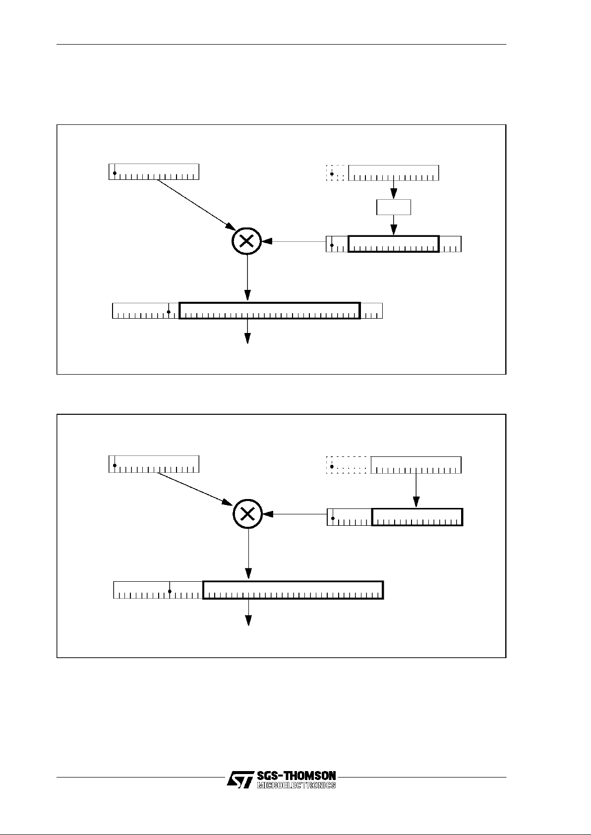
5.6 Scaling
62/205
Under shifting (by less than 8) is used for magnitude reduction (most suitable for
smacloop
) by 4 bits (x16) using mac_scale=1 or 8 bits (x256) using mac_scale=0.
Under-shifting by 4 bits is shown in Figure 5.5, and by8 bits in Figure 5.6.
Figure 5.5 Coefficientscaling with mac_mode set to 1
Figure 5.6 Coefficientscaling with mac_mode set to 0
Y data value
015
Add to internal accumulator
047
35
023
X data value
015
<< 4
4
4
Y data value
015
Add to internal accumulator
047 31
023
X data value
015

63/205
5 Multiply accumulate
5.6.3 Pre-scaling and rounding -
smacloop
The initial accumulator value must be loaded into the accumulator for the start of the
smacloop
instruction. The initial accumulator is either in Q31 format (
LongMode
), or
Q15 format (
ShortMode
) and is handled accordingly.
In
LongMode
,
• left shift by7 places (right 1 + left 8)
• sign extend from bit 38 to the most significantbit
• set bit 6 = 1 (for rounding)
In
ShortMode
,
• left shift by23 places (left 15 + left 8)
• sign extend from bit 38 to the most significantbit
• set bit 22 = 1 (for rounding)
Note that rounding is achieved by adding half of the least significant bit to the initial
value, which by associativity is equivalentto adding it to the finalvalue.
5.6.4 Pre-scaling and rounding -
biquad
The biquad instruction starts with an empty accumulator. Since the result is always
Q15 (equivalent to
ShortMode
), rounding is achievedby loading the accumulator with
222(which is half of the least significantbit of the result).
5.6.5 Post-scaling and saturation -
smacloop
At the end of a
smacloop
instruction the final accumulator value is saturated and
scaled to the appropriate format, according to mac_mode.
If either the
overfloworunderflow
bits in the status register are set, then the final value
is set to the appropriate exceptional value from Table 5.6. Note that this does not
involve testing the accumulator value, which is considered to be invalid if either of
these status register bits are set.
Otherwise, when the status register reports no overflow or underflow, bits 38 to 47
inclusive of the accumulator are tested for mutual equality.If they are all the same, the
accumulator value is well-formed and post-scaling is applied to produce the finalaccumulator value.
In
LongMode
,
• arithmetic right shift by 7 places(left 1 + right 8)
• truncate to low 32 bits
In
ShortMode
,
• arithmetic right shift by 23 places (right 15 + right 8)
• truncate to low 32 bits

5.6 Scaling
64/205
Howeverif the bits are not all equal, then an error has occurred. If the most significant
bit (bit 47) is zero then the overall result is positive, so the error is overflow.If the most
significant bit is 1 then the overall result is negative, so the error is underflow. The
appropriate status register bit (
overfloworunderflow
) is set accordingly,and the final
value is taken from Table 5.6.
5.6.6 Post-scaling and saturation -
biquad
The result of a
biquad
is always short (16-bits). The saturation test is from bit 38
upwards, and the
overflow/underflow
flags are set as required. Note the initial value of
the
overflow/underflow
flags is not taken into account. If a saturation error occurs,the
appropriate
ShortMode
value from Table 5.6 is used. If no error occurs,the scaling is:
• arithmetic right shift by 23 places
• truncate to low 32 bits
5.6.7 Error: load exceptional value
There are four exceptional values based on whether the result is to be delivered as a
ShortMode
(Q15) or
LongMode
(Q31) value, and whether the error was overflow or
underflow:
Note that in all cases the final value is placed in a 32-bit register (Areg).
5.6.8 Performance and interrupts
biquad
The
biquad
instruction takes 11 cycles to execute, assuming single cycle memory
accesses. The ST20-C1 cannot be interrupted during this period.
smacloop
A
smacloop
of n steps takes n+4 cycles to complete, assuming single cycle memory
accesses.
The ST20-C1 cannot be interrupted during this period, which may be up to about 8
microseconds (for single cycle memory and an operating frequency of 33 Mhz). The
user may split a long multiply accumulate into a set of shorter ones passing the intermediate accumulator value from one to the next.This will reduce interrupt latency,but
loses some numerical accuracy in that within a single
smacloop
intermediate values
are held to 48 bits of precision, while values passed from one
smacloop
to another
have at most 30 bits of precision (and are saturated).
mac_mode Overflow Underflow
ShortMode
00007FFF FFFF8000
LongMode
7FFFFFFF 80000000
Table 5.6 Exceptional values

65/205
5 Multiply accumulate
5.7 Data formats
This section gives details of the data formats used by the
smacloop
and
biquad
instructions.
A signed fractional number of Nbits is characterized as x.y, where x+y=N. This means
the number is made up from x bits beforethe binary point, an implied binary point, and
y fractional bits. Some examples are listed in Table 5.7.
5.7.1 Range
A valuenin x.y format has a range -2
x-1
≤n< 2
x-1
.
For example, a value in the format 1.15 has range -1 ≤n< 1, and the format2.14 has
range -2 ≤n<2.
5.7.2 Multiplication
The characteristic of the product of two fractional values is given by:
a.b * c.d = a+c.b+d
5.7.3 Supported formats
Table 5.8 shows the data formats formultiply-accumulate operations supported by the
ST20-C1.
Note that a Q15 value may be (optimally) stored in a 16-bit field, or a wider (>16-bit)
field with redundant sign bits. The two storage methods are described below.
5.7.4 Q15 in 16 bits
Q15 format is a 16-bit signed fractional value in the range -1 ≤ n < 1. The value is
stored in two’s-complement form with a sign bit (bit 15), an implied binary point
between bits 15 and 14, and 15 significantfractional bits (bit 14 to bit 0).
Totalbits Range Format Short name
32 -1 ≤ n < 1 1.31 Q31
16
-1 ≤ n<1
1.15 Q15
16 -2 ≤ n < 2 2.14 Q14
Table 5.7 Example data formats
Description Name Format
Signed 16-bit fractional Q14 14 significantfractional bits
Signed 16-bit fractional Q15 15 significantfractional bits
Signed 16-bit fractional Q31 31 significantfractional bits
Table 5.8 Supported multiply accumulate data formats

5.7 Data formats
66/205
A Q15 valuein a 16-bit field is organized as shown in Figure 5.7.
Figure 5.7 Q15 data format (16-bits)
The minimum and maximumrepresentable values are as shown in Table 5.9.
5.7.5 Q15 in an oversized field
When a Q15 value is stored in an oversizedfield, e.g.a 32-bit register, the significant
bits are placed at the least significantend of the field, and the value is sign-extended
to the width of the whole field.
The value still has the same range (-1 ≤ n < 1) and the same number of significant
bits.
A Q15 valuein a 32-bit field is organized as shown in Figure 5.8.
Figure 5.8 Q15 data format (32-bits)
The minimum and maximumrepresentable values are as shown in Table 5.10.
Hex Value Decimal Value
Minimum 8000 -1
Maximum 7FFF +0.9999
Table 5.9 Q15 limiting values
2
-1
-(20)2-22
-3
2
-142-15
binary point
sign bit
15 14 13 12 01Bit position
Most significant Least significant
-(20)-(20) -(20) -(20)-(20)2
-1
2
-14
2
-13
2
-15
binary point
sign bit
31 30 29
16 15 14
012Bit position
Most significant Least significant
Basic Q15 value
sign extended

67/205
5 Multiply accumulate
Memory access
A Q15 stored in memory may be loaded to Areg with a
lsxinc
instruction which will
automatically sign-extend the value.Similarly a Q15 maybe written to memory with a
ssinc
instruction (which will discard the top 16 bits).
Saturation
A well-formed Q15 value is sign extended to the width of the field,and so bits 15 to 31
inclusive will all be identical. Conversely, if the bits from 15 to 31 inclusive are not all
identical, then the value is not well-formed. It has either
overflowed
(if b31=0, so
positive) or
underflowed
(if bit31=1, so negative).
A Q15 valuein Areg may be saturated with the sequence:
ldc 00007FFF;
order;
ldc FFFF8000;
order;
rev;
5.7.6 Q31 format
Q31 format is a 32-bit signed fractional value in the range -1 ≤ n < 1. The value is
stored in two’s-complement form with a sign bit (bit 31), an implied binary point
between bits 31 and 30, and 31 significantfractional bits (bit 30 to bit 0).
A Q31 valuein a 32-bit field is organized as shown in Figure 5.9.
Figure 5.9 Q31 data format
The minimum and maximumrepresentable values are as shown in Table5.11.
Hex Value Decimal Value
Minimum FFFF8000 -1
Maximum 00007FFF +0.9999
Table 5.10 Q15 limiting values
2
-1
-(20)2-22
-4
2
-3
2
-5
2
-30
2
-29
2
-31
binary point
sign bit
31 30 29 28 27 26 012Bit position
Most significant Least significant

5.7 Data formats
68/205
Hex Value Decimal Value
Minimum 80000000 -1
Maximum 7FFFFFFF +0.99999999
Table 5.11 Q31 limiting values

69/205
5 Multiply accumulate

70/205
6 Exceptions
This chapter describes exceptions and how to use them. The architecture of the
ST20-C1, including the registers and memory arrangement, are described in Chapter
3. A full list of constants and data structures is given in Appendix A.
An
exception
is an exceptional event detected by the ST20-C1 core, which causes a
context switch from the normal flow of an executingprogram. The eventtriggering the
exception may be generated by software inside the core, in which case it is called a
trap. Otherwise, the event may be a hardware signal from outside the core, in which
case it is called an interrupt, except that the interrupt mayattempt to perform a scheduling action, which may cause a trap.
When an exception occurs the CPU changes contextto an
exception handler
, which is
a section of code only executed when an exception occurs. The process state
registers (Areg, Breg, Creg, Iptr, Wptr, Status and Tdesc) are saved while the
exception handler is running, and restored when it returns. Exception handlers for
traps are called
trap handlers
and exceptionhandlers forinterrupts are called
interrupt
handlers
. Normal processes which are not exception handlers are known as
user
processes
.
The exception handler is a transient process. Each exception handler starts execution
with a standard initial state, runs to completion and terminates with an empty workspace. When the triggering event occurs again, the handler is restarted from its
standard initial state and again runs to completion and terminates.
Exception handlers may be nested to arbitrary depth, but they are not re-entrant, so
care should be taken to ensure that the exception which caused the handler to run
cannot occur while the handler is running, trapped or interrupted. The nesting of
exceptions is illustrated in Figure 6.1.
Figure 6.1 Nested exceptions
User
process
User
process
Exception 1 taken - state of user process saved
Exception 2 taken - state of exception 1 saved
Exception 2 returns - state of exception 1 restored
Exception 1 returns - state of user process restored
Exception 1 executing
Exception 1 executing
Exception 2 executing

71/205
6 Exceptions
Exception handler code is completed byexecuting the
eret
instruction, which restores
the state of the interrupted or trapped process. When an interrupt handler executes
eret
, it also signals to the interrupt controller that the interrupt has completed. This
allows the interrupt handler to start a lower priority waiting interrupt if required.
The exception instructions are listed in Table 6.1.
6.1 Exception levels
All exception handlers are identifiedby an integer called the
exceptionlevel
. Exception
levels 0 to
HighestException
(255) are available for user-defined exceptions, while
system exceptions have negative levels, as defined in Table 6.2.
Any exception may be triggered from software with the
ecall
instruction. User-defined
exceptions can be interrupt handlers, user processes waiting for DMA peripherals or
trap handlers used as system calls by executing
ecall
.
System exceptionsare traps which maybe triggered automatically when the CPU is in
certain states. They are intended mainly for operating system kernels to trap scheduling eventsand for debuggers to trap breakpoints. The circumstances in which each
system trap is taken are as follows:
• el_breakpoint_trap
This trap is taken when either a
breakpoint
instruction is executed or a diagnostic controller (DCU) signals to the CPU requesting a breakpoint. If the trap
is null then the process continues.This trap is used by debuggers.
Mnemonic Name
ecall
exception call
eret
exception return
breakpoint
breakpoint
Table 6.1 Exception instructions
Exception level Name Circumstances when taken if not null
0 - 255 -
Interrupt, system call, DMA user process.
-1 el_breakpoint_trap
breakpoint
instruction executed or DCU break-
point request.
-2 el_illegal_instr_trap
Illegal op-code encountered.
-3 el_idle_trap
CPU becomes idle.
-4 el_schedule_exception_trap
Schedule a user process as an exception.
-5 el_run_trap
Execute a
run
instruction.
-6 el_stop_trap
Execute a
stop
instruction.
-7 el_timeslice_trap
Take a timeslice.
Table 6.2 Exception levels

6.2 Exception vector table
72/205
• el_illegal_instr_trap
This trap is taken when the CPU encounters an instruction with an illegal opcode. If the trap is null then the instruction is treated as a
nop
.
• el_idle_trap
This trap is taken when the CPU becomes idle, i.e. the current process executes a
stop
when there are no active processes waiting for CPU time, or a
timeslice
is trapped or interrupted sothat there are no active processes waiting
when the CPU attempts to start the next process. If the trap is null then the
CPU waits for an interrupt or for a process to be scheduled. This trap is used
by software scheduling kernels.
• el_schedule_exception_trap
This trap is taken when an interrupt is received from a peripheral and the
exception level is assigned to a user process, which will generally be descheduled waiting for the peripheral to complete a job. If the trap is null then the user
process is queued. This trapis used by software scheduling kernels.
• el_run_trap
This trap is taken when the
run
instruction is executed. If the trap is null then
the CPU adds the process to the back of the scheduling queue. This trap is
used bysoftware scheduling kernels.
• el_stop_trap
This trap is taken when the
stop
instruction is executed. If the trap is null then
the current process is descheduled and the CPU starts executing the process
on the front of the scheduling queue,or goes idle if there is none. This trap is
used bysoftware scheduling kernels.
• el_timeslice_trap
This trap is taken when a timeslice is due and enabled and the
timeslice
instruction is executed.If the trap is null then the current process is timesliced,
i.e. placed on the back of the scheduling queue. This trap is used by software
scheduling kernels.
Scheduling and timeslices are discussed in Chapter 7. Using user processes as
exceptions to handle peripherals is described in section 4.11.
6.2 Exception vector table
The
exception vector table
maps each exception level to a user process or exception.
The base of the exception vector table is at the fixed address
ExceptionBase
(#80000040) in on-chip memory, and the exception level is the word offset from the
ExceptionBase
to the vector. Thus the exception level is used as an index into the
exception vector table.
The address of the user process or exception is always word aligned, and so has bits
0 and 1 set to zero. The entry in the exception vector table is a
descriptor
, which
consists of the address of the user process or exceptionORed with a type. The
type
is

73/205
6 Exceptions
bit 0 of the descriptor, and so can be either
ExceptionProcessType
(which has the
value 1) or
UserProcessType
(which has the value0). The type allowseach exception
levelto be assigned to one of the following:
• an exception handler. The entry for an exception handler is the address of the
exception control block (as described in section 6.3) bitwise ORed with
ExceptionProcessType
to indicate an exception.
• a user process waitingfor a peripheral (as described in section 4.11).The entry
for a user process is the task descriptor (i.e. the address of the process control
block) bitwise ORed with
UserProcessType
to indicate a user process.
• the null entry
NotProcess
. The CPU treats null entries as disabled exceptions.
When the exception is triggered, the CPU looks in the table entry for the requested
exception level. If the value in the table is
NotProcess
then no exception or trap is
taken and the CPU continues with the default behavior. Otherwise, if bit 0 is
UserProcessType
then the address part of the value is assumed to be a valid task
descriptor of a process. If bit 0 is
ExceptionProcessType
, then the address part is
assumed to be a pointer to a validexception control block.
Using user processes as exceptions to handle peripherals is described in section
4.11. The rest of this chapter refers only to exceptions.
Typically a separate descriptor is used foreach interrupt leveland system call, so that
this scheme providesa system of vectoredinterrupts and system calls. The exception
handler is then executed,and can itself be interrupted or trapped.
6.3 Exception control blockand the saved state
When an exception is taken, the state is saved in the exception control block. The
evaluation stack, status register, Iptr, Wptr and Tdesc are automatically saved on
taking the exception and restored on returning. This is done to enable any exception
handler to have direct access to the state of the underlying process and is required for
some software scheduler implementations.
The constants in Table 6.3 definethe locations in the control block.
Wordoffset Name Purpose
7 ex.HandlerIptr
Exception handler instruction pointer.
6 ex.InterptdStatus
Interrupted or trapped process status register.
5 ex.InterptdTdesc
Interrupted or trapped process task descriptor.
4 ex.InterptdIptr
Interrupted or trapped process instruction pointer.
3 ex.InterptdWptr
Interrupted or trapped process workspace pointer.
2 ex.InterptdCreg
Interrupted or trapped process Creg.
1 ex.InterptdBreg
Interrupted or trapped process Breg.
0 ex.InterptdAreg
Interrupted or trapped process Areg.
Table 6.3 Exception control block

6.4 Initial exception handler state
74/205
The control block is at the initial Wptr for the exception handler, so the locations are
word offsets from the initial Wptr of the exception handler. The initial Wptr is the
address of the exception control block which is the address part of the entry in the
exception vector table.
6.4 Initial exception handler state
When the exceptionhandler starts, Wptr is set to the address of the exceptioncontrol
block.The work space of the exceptionhandler is normally belowthe control block, so
like a function or procedure call, one of the first actions of the exception handler code
is to adjust the Wptr downwards to create space for local variables using
ajw
. The
Wptr must be adjusted backup again beforethe handler returns.
The initial Iptr of the exception handler is the valueloaded from ex.HandlerIptr in the
exception control block.The state of the interrupted or trapped process is savedin the
exception control block.If the exception is an idle trapthen the saved state is the state
of the last descheduled process. Initially the status register is set to the values shown
in Table 6.4.
If the exception handler is interrupting a user process, then the address of the
exception control block(i.e. the user process state) is left in Tdesc. If necessary,the
exception handler can save this address. If a sequence of nested interrupts has
Field or bit Value
mac_count As in the interrupted or trapped process.
mac_buffer As in the interrupted or trapped process.
mac_scale As in the interrupted or trapped process.
mac_mode As in the interrupted or trapped process.
global_interrupt_enable False if exception is a trap, otherwise preserved.
local_interrupt_enable As in the interrupted or trapped process.
overflow False.
underflow False.
carry False.
user_mode False.
interrupt_mode True if any interrupts are running, false otherwise.
trap_mode True if exception is a trap, false otherwise.
sleep False.
reserved Undefined.
start_next_task False.
timeslice_enable False.
timeslice_count As in the interrupted or trapped process.
Table 6.4 Exception handler initial status register

75/205
6 Exceptions
occurred then this is the only way that the nested interrupts can identify the state of
the user process.
If the exception is a schedule_exception trap then the trap handler also needs to
know the process due to be scheduled. The descriptor of the process (as held in the
exception vector table) is saved at
SavedTaskDescriptor
near the bottom of the
address space.
6.5 Restrictions on exception handlers
Exception handlers cannot be queued, so they must not deschedule. This means that
the following are not permitted inside exceptionhandlers:
• the
stop
instruction;
• the
timeslice
instruction.
Exception handlers may be nested to arbitrary depth, but they are not re-entrant, so
care should be taken to ensure that the exception which caused the handler to run
cannot occur while the handler is running,trapped or interrupted.
6.6 Interrupts
All interrupts, whether from on-chip peripherals or external pins, are routed through an
interrupt controller,which is normally an on-chip peripheral. The interrupt controller is
responsible for arbitration between multiple interrupt signals. The design of the
interrupt controller varies between ST20 variants. Typically, interrupt priorities are
managed by the interrupt controller, which will usually track the priority of the highest
level task currently executed by the core, and will interrupt the ST20-C1 again if a
higher priority interrupt occurs.
When an interrupt is requested by the interrupt controller, the ST20-C1 always
changes contextto the appropriate interrupt handler.An interrupt request is accompanied by an identifier for the interrupt handler, which is the exception level. The ST20C1 scheduler uses the exception level from the interrupt controller to start the appropriate interrupt handler.
The CPU also sets the interrupt_mode bit in the status register and clears the
trap_mode and user_mode bits. The interrupt_mode bit indicates that an interrupt
handler is running, though it may have been trapped.
When the interrupt handler executes the
eret
instruction, the CPU signals to the
interrupt controller that the handler has returned. This allowsthe interrupt controller to
keep track of which interrupt handlers are running, so that it can start a low priority
waiting interrupt when a higher priority handler completes.
If the interrupt controller requests an interrupt level which has a null interrupt handler
then the CPU signals to the controller that the interrupthas completed.

6.7 Traps
76/205
6.7 Traps
The ST20-C1 has a system of traps which act as software generated interrupts. Any
level of exception can be called as a user exception using
ecall
. This mechanism can
be used for system calls to an operating system. In addition some special exception
levels are reserved for system use to provide for the trapping of breakpoints,
scheduling events, illegal operations and the machine becoming idle. The reserved
‘system’ exception levels are described in section 6.1.
If a system trap event occurs or a trap is called at an exception level which has a null
trap handler then the CPU ignores the trapand continues.
When a non-nulltrap handler is started, the trap_mode bit of the status register is set
and the user_mode bit is cleared. The interrupt_mode bit is not altered. The
trap_mode bit indicates that a trap handler is currently executing,so it is cleared if the
trap handler is interrupted.
6.8 Setting up the exception handler
To create an exception handler, an exception work space area must be created, with
enough space for the exception handler’s stack and 8 words at the top of the work
space for the exception control block, as defined in Table 6.3. For minimum interrupt
latency, interrupt handler control blocks should be in fast memory,preferably on-chip.
The normal work space and control block of an exception handler is shown in Figure
6.2. In the control block,ex.HandlerIptr must be initialized to point to the entry point of
the exception handler code.
Figure 6.2 Exception handler
ex.HandlerIptr
Pointer OR 1
Exception
handler code
entry point
Interrupted
or trapped state
Work
space
Exception
vector
table
Exception
level
(7 words)
(word offset)
ExceptionBase
Exception
Handler
Initial
exception handler
Wptr

77/205
6 Exceptions
The code of the exception handler may access or modify the state of the interrupted or
trapped process. The state of the interrupted or trapped process is stored in the
exception control block, which is located at the initial Wptr of the exception handler.
An exception handler must use
eret
to return to the interrupted or trapped process.
6.8.1 Enabling and disabling exceptions
When the exception handler has been created and initialized, the exception can be
enabled. The address of the exception handler control block, ORed with 1 to set the
exception type bit, must be written in the exception vector table at the level for the
exception. To write an entry
control_block
with type
ExceptionProcessType
in the
exception vector table, the following code may be used:
ld control_block;ldc ExceptionProcessType;or;
ld ExceptionBase;
stnl exception_level;
For interrupts, both the
global_interrupt_enable
and
local_interrupt_enable
bits in the
status register must be set. In addition the interrupt controller may need to be initialized, including any interrupt enable bits and masks.
A trap can be disabled by writing
NotProcess
into the exception vector table.
Interrupts can be disabled in fourways:
1 Clearing the status register bit global_interrupt_enable disables all interrupts
until the bit is set by an explicit write to the status register.
2 Clearing the status register bit local_interrupt_enable disables all interrupts
until the current process is descheduled.
3 A single exception level can be disabled by writing
NotProcess
into the excep-
tion vector table.
4 The interrupt controller will generallyhave a means of disablinginterrupts indi-
vidually or globally bywriting to interrupt controller registers.

7.1 Processes
78/205
7 Multi-tasking
This chapter describes the features of the ST20-C1 core provided to support multitasking, and howto use them. The architecture of the ST20-C1, including the registers
and memory arrangement, are described in Chapter 3. Interrupts and traps are
described in Chapter 6. A full list of constants and data structures is given in Appendix
A.
Support is provided in the instruction set for timeslicing, scheduling processes and
manipulating queues of processes.
7.1 Processes
A process (also known as a task or thread) is an independent unit of software with a
single thread of control, i.e. a sequential algorithm. Any number of processes may be
run. A process which has been started but not terminated may be in one of several
different states:
•
executing
on the CPU;
•
interruptedortrapped
by an exception;
•
inactive
, i.e.waiting for a peripheral or semaphore signal;
• waiting for CPU time.
A process that is not inactive is said to be active. A process that is not executing or
interrupted is said to be descheduled. The states and main transitions are shown in
Figure 7.1. The scheduling transitions can be trapped so that a software scheduling
kernel can modify the transitions and so change the scheduling behavior,for example
by providing a system of process priorities.
Figure 7.1 Process states and main transitions
Waiting
forCPU
time
Executing
Interrupted
Inactive
Descheduled
processes
Active
processes
Interrupt
or trap
Return
Event
Terminate
Run
Terminated
Not started
Descheduled
Timeslice
or
trapped

79/205
7 Multi-tasking
A process state is held in memory and the CPU registers. Sufficient of the register
state must be saved when the process is interrupted or a context switch occurs, so
that the process can be reloaded and continueexecution at a later time. The register
state consists of:
• the instruction pointer register;
• the work space pointer register;
• the task descriptor register;
• the evaluation stack registers;
• the status register.
In order to save memory space and contextswitch time, processes are only descheduled when the evaluationstack and status register are empty.This is achievedby only
allowing processes to deschedule at certain instructions, called deschedule instructions, after which the finalvalues in the evaluation stack are undefinedand the status
register is reset to a defaultvalue. The deschedule instructions are
stop
and
timeslice
.
Table 7.2 lists the multi-tasking instructions.
7.2 Descheduled processes
If the process is waiting for a peripheral or a semaphore or descheduled bya timeslice
then the evaluation stack is not saved.The instruction pointer and Wptr are saved in
the
process descriptor block
. The task descriptor is the address of the process
descriptor block. It therefore identifies the waiting process and points to its saved
state. The task descriptor is a fixed address for each process, unlike the Wptr which
changes as the code executes. When the process is running, the task descriptor is
held in the Tdesc register.
Mnemonic Name
run
Run process
stop
Stop process
timeslice
Timeslice
ldtdesc
Load task descriptor
enqueue
Enqueue a process
dequeue
Dequeue a process
Table 7.2 Multi-tasking instructions
Word offset Slot name Purpose
2 pw.Iptr The process saved instruction pointer.
1 pw.Wptr The process saved work space pointer.
0 pw.Link The link to the next process in the queue.
Table 7.1 Process descriptor block

7.3 Queues
80/205
The structure of the process descriptor block is shown in Table7.1. When the process
is not executing,it contains the savedwork space pointer and instruction pointer of the
process, plus a queue link if the process is in a queue.
Figure 7.3 illustrates a descheduled process.
Figure 7.3 A descheduled process
7.3 Queues
There may be any number of processes waiting for execution,so a queue (i.e. a linked
list) of waiting processes is formed, called the
scheduling queue
. This is an example
of a general queue supported bythe instruction set for queueing waiting processes.
A queue is a linked list of process control blocks, formed by links included in the
process control blocks. Each link points to the control blockof the next process in the
queue unless it is the last in the queue,which is undefined.
The front and back pointers of a queue are held in a queue control block,as shown in
Table 7.2. The queue control blockis held in memory,and the address of the block is
the identifierof the queue.
A complete queue is illustrated in Figure 7.4. In the case of the scheduling queue,the
control block is stored at the reserved address called
SchedulerQptr
(which has the
Wordoffset Slot name Purpose
1 q.BPtrLoc The backof the queue.
0 q.FPtrLoc The front of the queue.
Table 7.2 Queue control block
Process
work space
(stack)
Work space pointer
Link
Next process
Task descriptor
Code
local
Iptr
Process descriptor block

81/205
7 Multi-tasking
value
MostNeg
) at the bottom of the memory space.
Figure 7.4 A process queue
7.4 Timeslicing
The ST20-C1 includes support for timeslicing. Timeslicing is a safeguard in a multitasking environment to preventany one process from taking too muchprocessor time.
Exception handlers are not timesliced.
A timeslicing counter is provided as a field of the status register called the
timeslice_count. It is reset to
MaxTimesliceCount
each time a user process is loaded
from the scheduling queue into the CPU.The counter is decremented regularly until it
reaches 0, and then staysat 0. A timeslice is due when the counter valueis 0.
If a
timeslice
instruction is executedwhen atimeslice isdue and timeslicing is enabled
then:
• the timeslice trapwill be takenif it is installed;
• otherwise the current process will be timesliced, i.e. the current process is
placed on the back of the scheduling queue and the process on the front of the
scheduling queue is loaded into the CPU forexecution.
If an exception occurs, the value of the counter is saved with the status register and
reloaded when the interrupted or trapped process is restarted. This ensures that a
process will be executedfor roughly the same time regardless of whether it wasinterrupted or trapped.
The timeslice_enable bit of the status register can be used to enable or disable
timeslicing. Timeslicing is enabled when the bit is set. This bit is preserved when a
process is descheduled, so it maybe treated as global among user processes.Timeslicing must not be enabled in exception handlers.
Front
Back
Front Back
Queue control block
Process descriptor blocks
Wptr
Iptr
Wptr
Iptr
Wptr
Iptr
Wptr
Iptr

7.5 Inactive processes
82/205
7.5 Inactive processes
An inactive process is a process that is waiting for some event to occur, such as a
process executing a
run
instruction or a peripheral completing a DMA. An inactive
process cannot continue evenif the CPU is idle.Inactive processes are not polled, but
should be rescheduled bythe eventfor which they are waiting.
A process becomes inactive by saving its own state and then executing the
stop
instruction.
stop
automatically saves the Iptr and Wptr in the process control block.
The code should save the Tdesc in an appropriate place where the awaited event can
find it. The Tdesc points to the process control block.The Iptr is loaded onto the evaluation stack using
ldpi
, the Wptr using
ldlp 0
and the Tdesc using
ldtdesc
. For
example:
ldtdesc; ld tdesc_save_address;stnl 0;
stop;
Two mechanisms are provided for rescheduling inactiveprocesses:
• Executing the
run
instruction. This allows other processes to reschedule an
inactive process. For example, this is used when semaphore signalling to a
waiting process and could be used by other communications, possibly implemented byan operating system.
• Scheduling an exception. This allows external devices to reschedule an inactive process. For example, this is used by DMA peripherals to wake a process
waiting for the DMA to complete. Exception scheduling is described in section
4.11.
The
run
instruction takes a task descriptor in Areg and adds the process control block
to the back of the scheduling queue.For example:
ld task_descriptor; run;
Inactive processes may need to be queued, for example while waiting for a semaphore. The semaphore queue handling is incorporated into the signal and wait instructions, but for other queues the instructions
enqueue
and
dequeue
are needed.
Enqueue
will add a process to the backof an arbitrary queue,and
dequeue
will take a
process from the front of the queue.
7.6 Descheduled process state
When a process restarts after an interrupt or trap, the entire state is loaded from the
saved state. However, when the process starts or restarts after being descheduled,
the CPU makes assumptions about the state of the process, since not all the state
was saved.
Wptr and Iptr are set to the values saved in pw.Wptr and pw.Iptr of the process
descriptor block.
The status register is set to the valuesshown in Table 7.3. The global interrupt enable
and timeslice enable are global status bits, and are carried over from one process to
the next when a contextswitch occurs.

83/205
7 Multi-tasking
7.7 Initializing multi-tasking
7.7.1 Initializing the scheduling queue
Before multi-tasking operations can be performed, the scheduling queue must be
initialized. The scheduling queue is described in section 7.3. The queue must be
initialized by setting it to empty,which means setting the front pointer to empty:
ld MostNeg; ld SchedulerQptr; stnl q.FPtrLoc;
7.7.2 Creating and starting a process
A process consists of code,a work space area, a process control block and the values
for the Iptr, Wptr and Tdesc. To create a process, a large enough work space is
created, and a process control blockof three words.It may be convenientto put all the
process control blockstogether in one area of memory.For fast context switches and
minimal interrupt latency,process control blocks should be in on-chip memory.
The entry point for the process code is written into pw.Iptr of the process control
block. The address of the top of the work space is written into pw.Wptr of the process
control block, so the process code must adjust the initial Wptr down using
ajw
to
create space forlocal variables.
Field or bit Value
mac_count As in previous process.
mac_buffer As in previous process.
mac_scale As in previous process.
mac_mode As in previous process.
global_interrupt_enable As in previous process.
local_interrupt_enable Set.
overflow False.
underflow False.
carry False.
user_mode True.
interrupt_mode False.
trap_mode False.
sleep False.
reserved Undefined.
start_next_task False.
timeslice_enable As in previous process.
timeslice_count MaxTimesliceCount.
Table 7.3 Restarted process status register

7.8 Scheduling kernels
84/205
The following code would set up a process control block:
ld entry_point; ld control_block;stnl pw.Iptr;
ld work_space_top; arot; stnl pw.Wptr;
The process is then inactive, so it can be added to the back of the scheduling queue
using
run
, exactly as in section 7.5.
7.8 Scheduling kernels
A scheduling kernel can be written to override the default scheduling behavior of the
ST20-C1, but still using the very fast micro-code scheduling. The basis of such a
scheduler would be trap handlers to trap the system exceptions el_idle_trap,
el_run_trap, el_stop_trap, el_timeslice_trap and el_schedule_exception_trap.
When these traps are taken, a scheduling event is due or the processor has become
idle. The trap replaces the default scheduling action. When the trap handler returns,
the CPU will continuewith the nextinstruction. Trapsare described in Chapter 6.
Additional system calls may be implemented by user-defined trap handlers, called
using
ecall
.
7.9 Semaphores
Semaphores are a mechanism for managing access to shared resources within a
multi-tasking environment.The semaphore operations are providedbythe instructions
listed in Table 7.4.
The semaphore instructions act on a semaphore control block,defined in Table7.5.
Each semaphore has a semaphore control block, which implements a linked list of
waiting processes and a count of free resources.The count should be initialized to the
total number of available resources (usually one), and the front list pointer should be
initialized to the empty value
NotProcess
. For fast signalling and minimal interrupt
latency,semaphore control blocks should be in fast memory,preferably on-chip.
Mnemonic Name
signal
signal
wait
wait
stop
stop process
run
run process
Table 7.4 Semaphore instructions
Word offset Slot name Purpose
2 s.Back The back of the semaphore waitinglist.
1 s.Front The front of the semaphore waiting list.
0 s.Count The unsignednumber of extraprocessesthat thesemaphorewill allow
to continue running on a
wait
request.
Table 7.5 Semaphore control block

85/205
7 Multi-tasking
7.9.1 Waiting for a resource
A process requesting a resource executes a wait (or P), which is the following code
sequence:
ld semaphore; wait;
cj CONTINUE;
stop;
CONTINUE:
The
wait
instruction is executed, with a pointer to the semaphore control block in
Areg. The action of
wait
depends on the count in the semaphore control block. If the
count is not zero, then a resource is free, so the count of free resources is decremented and the value
false
is left in the Areg to indicate that the process can
continue. If the count is zero then there are no free resources, and the process is
added to the list of waitingprocesses, and the value
true
is left inAreg to indicate that
the process must wait. A conditional jump then tests Areg and performs a
stop
if the
process must wait.
stop
saves the Iptr and Wptr and deschedules the process,which
will wait on the semaphore queue until another process performs a
signal
and subse-
quently restarts the process with a
run
instruction.
7.9.2 Freeing a resource
When a process finishes with a resource and can free it, it performs a signal (or V),
which is the followingcode sequence:
ld semaphore; signal;
cj CONTINUE;
run;
CONTINUE:
The
signal
instruction is executed, with a pointer to the semaphore control block in
Areg. The action of
signal
depends on whether a process is waiting or not. If the front
pointer of the process waitinglist is empty then there are no processes waiting,so the
count is incremented and Areg is set to
false
. Otherwise, at least one process is
waiting, so the firstprocess is removed from the list and placed in the Breg, and Areg
is set to
true
. A conditional jump tests Areg and performs a
run
to restart the process
if there wasone waiting.
7.10 Sleep
When the ST20-C1 becomes
idle
it disables counter distribution to its circuits and
consumes a very small amount of electrical power; this is known as
sleep
mode. The
counters are re-enabled and normal operation resumes automatically and instantly
when either an interrupt or a software reset from the diagnostic controller is received.
Sleep mode mayalso be triggered directly from software by setting the sleep bit in the
status register:
ldc sleep; bitmask; statusset;
In this case also, sleep mode persists until the next interrupt or software reset.

7.10 Sleep
86/205

87/205
8 Instruction Set Reference
8 Instruction Set Reference
The following pages definethe actions of each instruction in the ST20-C1 instruction
set. The notation used is described in Chapter 2. The use of the instructions is
described in Chapter 4, Chapter 6 and Chapter 7. The constants and data structures
are listed in Appendix A.

88/205
adc
n add constant
Code: Function 8
Description: Add a constant to Areg.
Definition:
if (sum > MostPos)
{
Areg′←sum − 2
BitsPerWord
if (Status′
underflow
≠ set )
Status′
overflow
← set
}
else if (sum < MostNeg)
{
Areg′←sum + 2
BitsPerWord
if (Status′
overflow
≠ set )
Status′
underflow
← set
}
else
{
Areg′←sum
}
where sum = Areg + n
– the value of
sum
is calculated to unlimited precision
Status Register:
Overflow or underflowbit may be set.
Comments:
Primary instruction.
See also:
add addc ldnlp
section 4.4.

89/205
8 Instruction Set Reference
add
add
Code: F4
Description: Add Areg and Breg.
Definition:
if (sum > MostPos)
{
Areg′←sum − 2
BitsPerWord
if (Status′
underflow
≠ set )
Status′
overflow
← set
}
else if (sum < MostNeg)
{
Areg′←sum + 2
BitsPerWord
if (Status′
overflow
≠ set )
Status′
underflow
← set
}
else
{
Areg′←sum
}
Breg′←Creg
Creg′←Areg
where sum = Areg + Breg
– the valueof
sum
is calculated to unlimited precision
Status Register:
Overflow or underflowbit may be set.
Comments:
Secondary instruction.
See also:
adc addc
section 4.4.

90/205
addc
add with carry
Code: 21 F0
Description: Add Areg and Breg, unsigned, with carry propagation. This instruction
is provided for long arithmetic; address calculations may be performed with
add,sub
and
adc
without affecting the carry flag.
Definition:
if (sum < 2
BitsPerWord
)
{
Areg′
unsigned
← sum
Status′
carry
← clear
}
else
{
Areg′
unsigned
← sum - 2
BitsPerWord
Status′
carry
← set
}
Breg′←Creg
Creg′←Areg
where sum = Areg
unsigned
+ Breg
unsigned
+ Status
carry
– the value of
sum
is calculated to unlimited precision
Status Register:
Carry bit is set or cleared.
Comments:
Secondary instruction.
See also:
adc add subc
section 4.4.

91/205
8 Instruction Set Reference
ajw
n adjust work space
Code: Function B
Description: Move the workspace (stack) pointer bythe number of words specified in
the operand, in order to allocate or de-allocate workspace stack slots.
Definition:
Wptr′←Wptr @ n
Status Register:
No effect
Comments:
Primary instruction.
See also:
fcall gajw
section 4.10.

92/205
and
and
Code: F9
Description: Bitwise AND of Areg and Breg.
Definition:
Areg′←Breg ∧ Areg
Breg′←Creg
Creg′←Areg
Status Register:
No effect
Comments:
Secondary instruction.
See also:
not or xor
section 4.8.

93/205
8 Instruction Set Reference
arot
anti-rotate stack
Code: F3
Description: Rotate the evaluationstack downwards. This instruction maybe used to
recover values rotated onto the bottom of the stack,e.g. bycj.
Definition:
Areg′←Creg
Breg′←Areg
Creg′←Breg
Status Register:
No effect
Comments:
Secondary instruction.
See also:
dup rev rot
section 4.1.

94/205
ashr
arithmetic shift right
Code: 21 FF
Description: Perform an arithmetic shift right of Breg by Areg bits, copying the sign
bit into the vacated bits. Breg, not Areg, is rotated into Creg, to preserve the value
rather than the shift length.
Definition:
Areg′←(Breg >>
arith
Areg
unsigned
)
Breg′←Creg
Creg′←Breg
Status Register:
No effect
Comments:
Secondary instruction.
If Areg is not in the range 0..31 then the result is undefined.
See also:
shl shr
section 4.9.

95/205
8 Instruction Set Reference
biquad
biquad IIR filter step
Code: 21 F7
Description: Execute a step of a biquad IIR filter on vectors of 16-bit values. Areg
points to the C coefficient vector, Breg points to the X input data vector and Creg
points to the Y results vector. Areg must be word-aligned and Breg and Creg halfword aligned.
biquad
increments Breg and Creg by 2 bytes and performs the five
multiply accumulates Y[2] = X[0].C[0] + X[1].C[1] + X[2].C[2] + Y[0].C[3] + Y[1].C[4].
Definition:
if (
overflow
)
if (Status′
underflow
≠ set ) Status′
overflow
←set
else if (
underflow
)
if (Status′
overflow
≠ set ) Status′
underflow
←set
else
{
sixteen′[Creg + 4] ← acc >>
arith
23
Breg′←Breg + 2
Creg′←Creg + 2
}
where acc = 1 << 22 + ((sixteen[Areg] << shift) × sixteen[Breg])
+ ((sixteen[Areg+2] << shift) × sixteen[Breg+2])
+ ((sixteen[Areg+4] << shift) × sixteen[Breg+4])
+ ((sixteen[Areg+6] << shift) × sixteen[Creg])
+ ((sixteen[Areg+8] << shift) × sixteen[Creg+2])
–
the value of
acc
is calculated to 48-bit precision
if (Status
mac_scale
= 3) shift = 9
else shift = 4 × Status
mac_scale
Status Register:
May set underflowor overflow.
Comments:
Areg must be word-aligned.
Breg and Creg must be half-word aligned, and must either be both word-aligned
or neither word-aligned.
This instruction may take 8 memory accesses, which will affect interrupt latency.
See also:
mac, smacloop, umac
Chapter 5.

96/205
bitld
load bit
Code: 22 F3
Description: Get a bit of Breg. The bit number is given by Areg. Breg is rotated into
Creg, to preservethe value rather than the bit number.
Definition:
Areg′←(Breg >> Areg) ∧ 1
Breg′←Creg
Creg′←Breg
Status Register:
No effect
Comments:
Secondary instruction.
Areg must be in the range 0..31.
See also:
bitst bitmask
section 4.8.

97/205
8 Instruction Set Reference
bitmask
create bit mask
Code: 22 F5
Description: Create a bit mask with a single bit set. The value in Areg indicates the
bit that is to be set.
Definition:
Areg′←1 << Areg
Status Register:
No effect
Comments:
Secondary instruction.
Areg must be in the range 0..31.
See also:
bitld
section 4.8.

98/205
bitst
store bit
Code: 22 F4
Description: Overwrite the bitposition Areg of the value in Creg with a single bit with
the value given by Breg. Breg is rotated into Creg, to preserve the value rather than
the bit number.
Definition:
Areg′←(Creg ∧ ~(1 << Areg)) ∨ (Breg << Areg)
Breg′←Creg
Creg′←Breg
Status Register:
No effect
Comments:
Secondary instruction.
Areg must be in the range 0..31.
Breg must be 0 or 1.
See also:
bitld bitmask
section 4.8.

99/205
8 Instruction Set Reference
breakpoint
breakpoint
Code: FF
Description: Take a breakpoint trap if a breakpoint trapis installed.
Definition:
if (
breakpoint trap installed
)
take breakpoint trap
Status Register:
If the trap is taken then the status register is saved and the trap handler status
register is loaded.
Comments:
Secondary instruction.
This instruction is a short secondaryinstruction, encoded in a single byte.
See also:
Chapter 6.

100/205
cj
n conditional jump
Code: Function A
Description: Jump if Areg is 0 (i.e. jump if
false
). The destination of the jump is
expressed as a byte offset from the instruction following the conditional jump.
Definition:
if (Areg = false)
Iptr′←
next instruction
+ n
else
{
Areg′←Breg
Breg′←Creg
Creg′←Areg
}
Status Register:
No effect
Comments:
Primary instruction.
The initial Areg can be recovered using
arot
.
See also:
eqc gt gtu j jab
section 4.6.
 Loading...