

SGS Thomson Microelectronics ST1353, ST1333, ST1331 Datasheet
272-bit EEPROM with Advanced Security Mechanisms
■ 5 V Single Supply Voltage
■ Counting Capability (two options)
5
– up to 32767 (8
– 8 times reloadable, up to 4095 (8
■ Active Authentication Function (ST1333/ 1353 )
■ Cipher Block Chaining Function (ST1353)
■ Memory Divided into :
– 16 bits of Circuit Identification
– 48 bits of Card Ident i fication
– 40 bits of Count Data
– 16 bits for Validation Certifica te
– 24 bits of Transport Code
– 64 bits of Issuer Data (ST1331) or
Authentication Secret Key (ST1333/13 53)
– 32 bits of Anti-tearing Flags (optional)
– 56 bits of User data (optionally not erasable)
■ 1 Million Erase/Write Cycle (minimum)
■ 10 Year Data Retention (minimum)
■ 3.5 ms Programming Time at 5 V (typical)
■ 500 µA Supply Current at 5 V (typical)
■ 250 µA Stand-by Current at 5 V (typical)
DESCRIPTION
The members of the ST1331/1333/1353 family are
principally designed for use in prepaid Phonec ard
applications. Each is a 272-bit EEPR OM device,
with associated security logic and special fuses to
control memory access. The m emory is a rranged
as a matrix of 34 x 8 cells, accessed in a serial bitwise fashion for reading and programming, and in
-1)
4
-1)
ST1331, ST1333
ST1353
6-Contact Memory Card IC
DATA BRIEFING
1
1
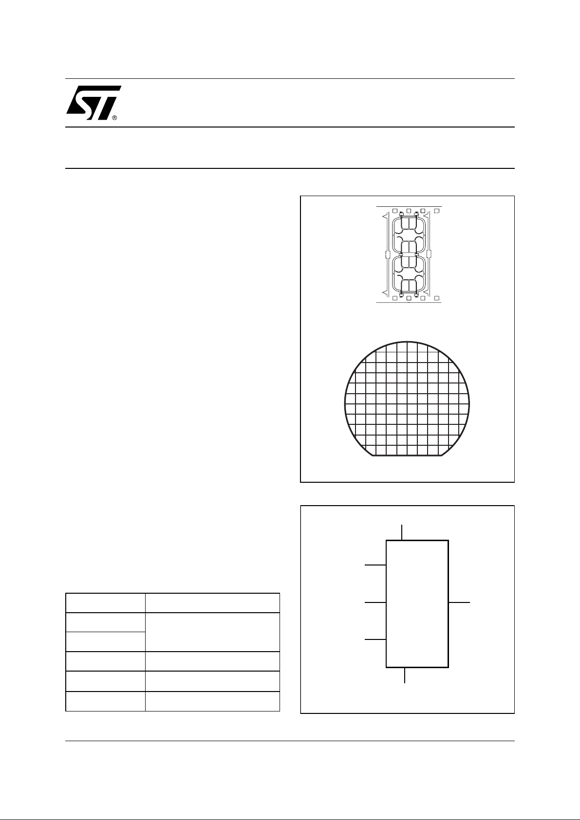
Micromodule
Wafer
Figure 1. Logic Diagram
V
RST
1
1
(D10)
CC
Table 1. Signal Names
CLK Clock
RST
Function code
B
I/O Data Input / Output
V
CC
GND Ground
October 1999
Complete data available under NDA.
Supply Voltage
CLK
B
ST1331
ST1333
ST1353
GND
I/O
AI03105b
1/3

ST1331, ST1333, ST1353
Figure 2. Me m ory Map
16 masked bits
48 bits
40 bits
8 bits
16 bits
64 bits
Circuit
Identification Area
Card Identification
Area (ID)
Data Area (CD)
(Counters and
Transport Code)
Reserved Area (RA)
Certificate (CER)
Issuer-Defined Area
(ST1331)
Authentication
Secret Key (SK)
(ST1333, ST1353)
Reserved Area
(RA)
0
16
64
104
112
128
192
32 bits
RAM1 (Write-Only)
0
(RN)
(ST1333, ST1353)
32
4 bits
4 bits
24 bits
32 bits
56 bits
Note: 1. The write-onl y RAM area (RN) is applicable only for the User Configuration.
Signature
Fuses
Unused
Anti-Tearing Flags
User-Defined Area
a byte-wise fashion for internal erasing. An on-chip
address counter provides an internal address
space of up to 512 bits.
Each member of the ST1331/1333/1353 family
has an identification data area, unit-counters (with
an anti-tearing mechanism for reliable usage in
open readers), a post validation certificate, an
256
260
264
288
320
376
Physical EEPROM CellsPhysical EEPROM CellsPhysical EEPROM Cells
issuer area (ST1331) or an aut hentication secret
key area (ST1333/1353), and a user area. This is
summarized in Figure 2.
The validation certificate allows the recognition of
the device by the appropriate security module.
The anti-tearing mechanism guards against extra,
spurious count signals being executed when the
AI03384
2/3
 Loading...