

SGS Thomson Microelectronics ST1284-03T8, ST1284-03A8, ST1284-02T8, ST1284-02A8, ST1284-01T8 Datasheet
1/7
ST1284-xxA8/T8
®
July 2002 - Ed: 1B
■
One device for parallel port termination
■
Compliant with IEEE1284 standard
■
EMI / RFI noise filtering
■
Highly integrated solution in 28 pin QSOP and
TSSOP packages
■ One single device provides the proper termina-
tion for 8 datalines, 1 strobe line, 4 control lines
and 4 statuts lines
■ In system ESD protection of ±15 kV (air dis-
charge) as per IEC61000-4-2 level 4
FEATURES
28
27
26
25
24
23
22
21
20
19
18
17
16
1514
13
12
11
10
9
8
7
6
5
4
3
2
1
Vcc Vcc VccVcc
Vcc
Vcc
Vcc
Vcc
Vcc
Vcc
Vcc
Vcc
Vcc
Gnd
Vcc
Vcc
Vcc
Vcc
Vcc
R1
C
R1CR1
R2
C
R1
R1
R1
R1
R1
R2
R1
R2
R1
R2
R1
R1
R2
C
Rs
C
Rs
C
Rs
C
Rs
C
Rs
C
Rs
C
Rs
C
Rs
Rs
C
C
C
C
C
C
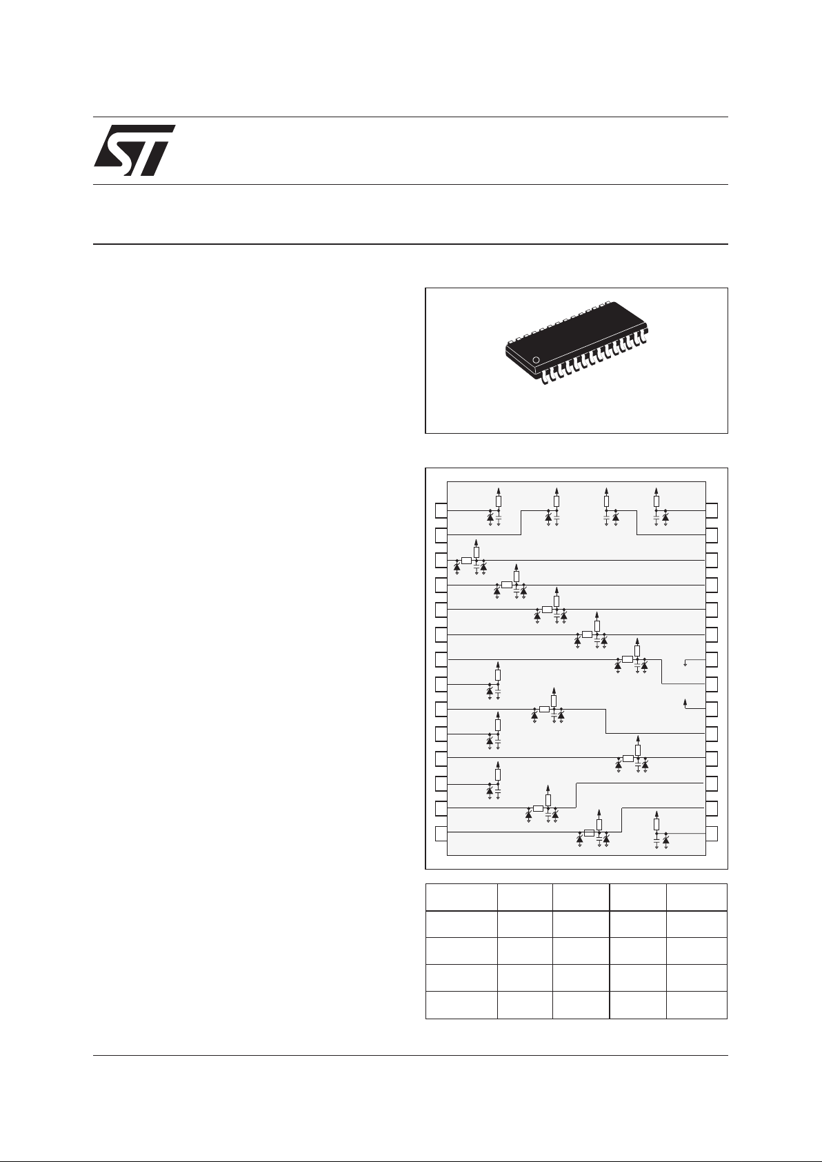
SCHEMATIC DIAGRAM
PARALLEL PORT SINGLE TERMINATION
NETWORK WITH ±15kV ESD PROTECTION
A.S.D.
TM
ECP/EPP Parallel Port termination on:
■
Desktops
■
Notebooks
■
Workstations
■
Servers
■
PC Peripherals
■
Set Top Box
MAIN APPLICATIONS
The ST1284-xxA8/T8 is a highly integrated termination forenhancedhigh speed parallel ports. The
integrated termination complies to the IEEE1284
Standard recommendations and government
EMC compatibility requirements. It is built around
two basic cells. The first one (Cell 1) provides line
termination, EMI filtering and ESD protection for
the Strobe and Datalines while the second one
(Cell 2) provides EMI filtering and ESD protection
for the Control and Status lines. In addition,
ST1284-xxA8 provides extra protection against
ESD. When tested according to IEC61000-4-2,
they withstand ±8kV contact discharges and
±15kV air-discharges, thereby providing to the
system the necessary robustness to meet up to
level 4of IEC61000-4-2, withoutthe need for additional ESD protection components. Cells 1 and 2
are described in more detail in figures 1 and 2.
DESCRIPTION
QSOP28 / TSSOP28
R1 R2
Rs
C
Code 01 4.7kΩ 4.7kΩ
33Ω
180pF
Code 02 2.2kΩ 2.2kΩ
33Ω
220pF
Code 03 1kΩ 5.1kΩ
39Ω
150pF
Tolerance ± 10% ± 10%
± 10%
± 20%
- IEC61000-4-2 ±15kV (airdischarge)
±8kV (contact discharge)
- MIL STD 883E - Method 3015-7 : Class 3
(human body model).
COMPLIES WITH THE FOLLOWING ESD
STANDARDS :
ST1284-xxA8/T8
2/7
Symbol Parameter Value Unit
V
PP
ESD discharge IEC61000-4-2, air discharge
±16 kV
ESD discharge IEC61000-4-2, contact discharge
±9 kV
ESD discharge - MIL STD 883E - Method 3015-7
±25 kV
V
cc
Supply voltage
5.5 V
P
r
Power rating per resistor
100 mW
P
P
Package Power rating
1W
T
op
Operating temperature range
0 to +70 °C
T
stg
Storage temperature range
-55 to +150 °C
T
j
Maximum operating junction temperature
125 °C
ABSOLUTE MAXIMUM RATINGS (T
amb
25°C)
Symbol Parameter Test condition Min. Typ. Max. Unit
I
R
Leakage current
V
cc
= 5.0V 10 µA
V
BR
Breakdown voltage
I
R
= 1mA 6 V
V
F
Forward voltage drop
I
F
= 50mA 0.9 V
ELECTRICAL CHARACTERISTICS (T
amb
= 25°C)
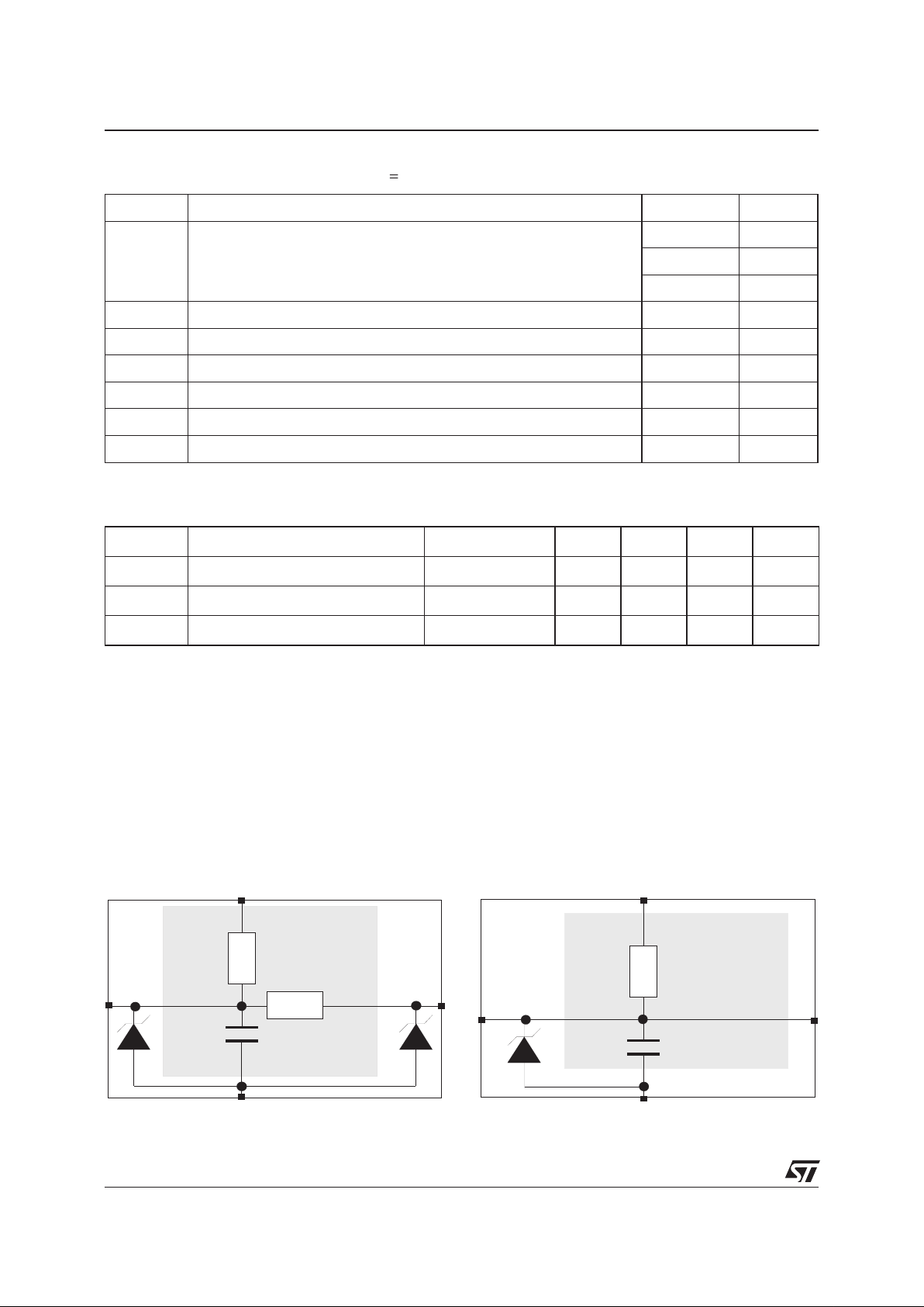
The ST1284-xxA8/T8 is built around the two basic cells described below which integrate the recommended IEEE1284 network and the ESD protection compatible with IEC61000-4-2 level 4
BASIC CELL CONFIGURATIONS
C
IEEE1284
Recommendation
Vcc
Gnd
Rp
Rs
Fig. 1:Cell 1 for line termination, EMI filtering and
ESD protection for the Datalines and Strobe signals. There are 9 of these cells inside the
ST1284-xxA8/T8
C
IEEE1284
Recommendation
Vcc
Gnd
Rp
Fig. 2: Cell 2 for EMI filtering and ESD protection
of the Control and Status signals. There are 8 of
these cells inside the ST1284-xxA8/T8
3/7
ST1284-xxA8/T8
14 Autofeed
15 Error
16 Reset
17 Select in
1 Strobe
2 Bit 1
3 Bit 2
4 Bit 3
5 Bit 4
6 Bit 5
7 Bit 6
8 Bit 7
9 Bit 8
13 Select paper
14
1
13
25
1
28
2
27
20
26
25
24
23
21
19
18
17
16
3
4
5
6
7
9
11
13
14
8
10
12
15
22
10 Acknowledge
11 Busy
12 Paper Out
Vcc
Vcc
Vcc
Gnd
ST1284-xxA8/T8
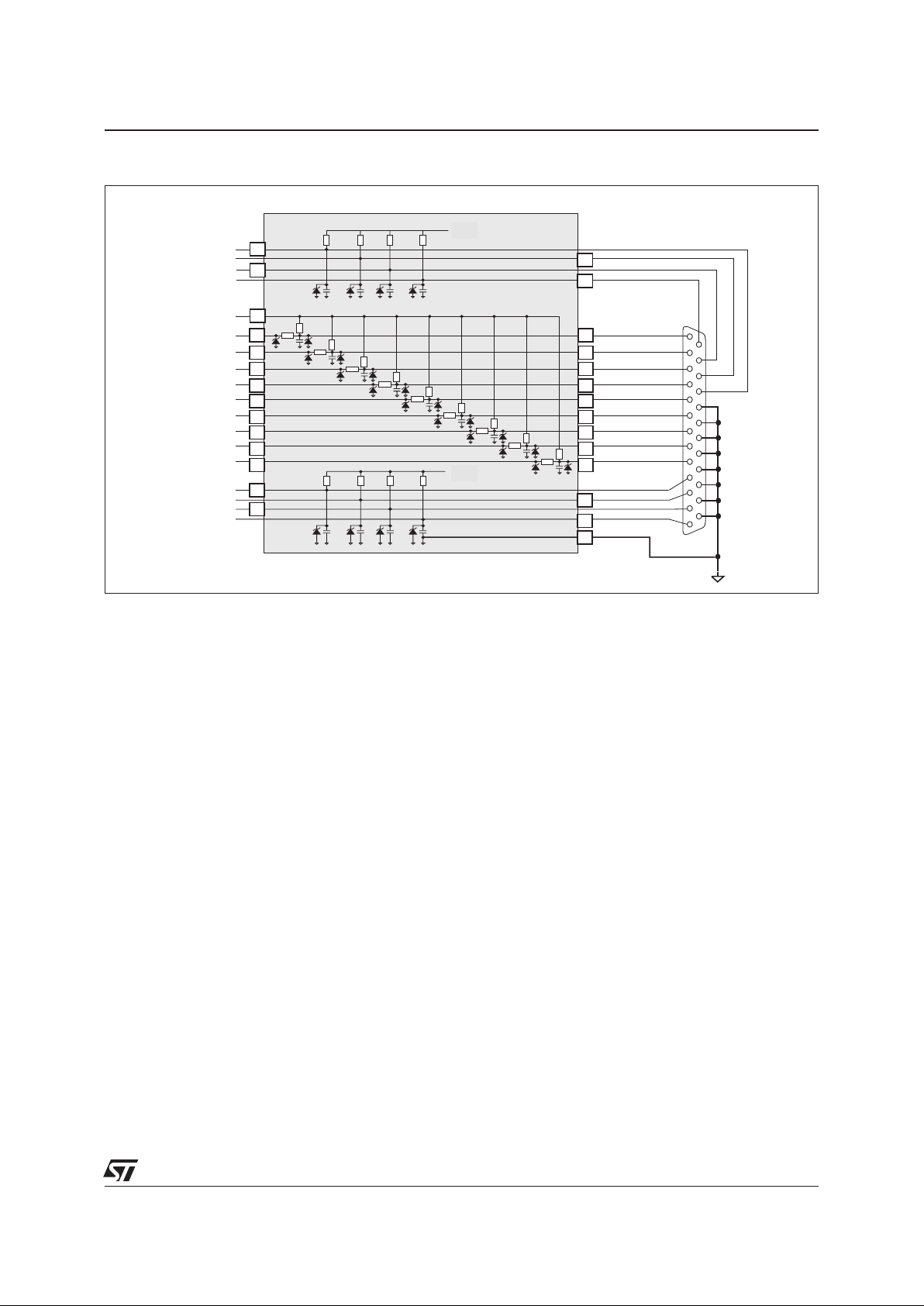
FUNCTIONAL DIAGRAM
Thefunctional diagram here above presentsa IEEE1284-Aconnector pinoutand show how to connect
the ST1284-xxA8/T8in order to correctlyterminate and filter the17 signal lines. TheIEEE1284-A connector is the PC standard for the host connection.
Control and status lines (from 10 to 17) only require a pull-up resistor (Rp) and a filter capacitor (C).
The data lines (from 2 to 9) and the STROBE (pin 1) also require a termination series resistor (Rs)
in addition to the pull-up resistor and a filter capacitor. The Vcc is connected to pin 20 and the
ground to pin 22.
The ST1284-xxA8/T8 can be used with all 3 types of connectors defined in the IEEE1284 standard:
- IEEE1284-A is a 25DB connector which is the PC standard for the host connection.
- IEEE1284-B is a 36 pin, 0.085 inch centerline connector used on the peripheral device.
- IEEE1284-C is a new 36 pin, 0.050inch centerline connector which can beused for both host and peripherals.
APPLICATION INFORMATION
 Loading...