

SGS Thomson Microelectronics ST10R272L-B0 Datasheet

®
ST10R272L-B0
16-BIT ROMLESS LOW VOLTAGE MCU WITH MAC
ERRATA SHEET
1 INTRODUCTION
This errata sheet describes the functional and electrical problems known in the step B0 of the
ST10R272L-B0. This is the erratasheet of the ST10R272L datasheet version 1.2 of apr il
2000.
2 FUNCTIONAL PROBLEMS
The following malfunctions are known in this step:
2.1 ST_PWRDN.1: EXECUTION OF PWRDN INSTRUCTION WHILE NMI
When PWRDN instruction is executed while NMI
should not be entered, and the PW RDN instruction should be ignored. Howe ver, under the
conditions described below, the PWRDN instruction may not be ignored, and no further instructions are fetched from external memory, i.e. the CPU is in a quasi-idle state. This problem will only occur in the following situations:
1) the instructions following the PW RDN instruction are located in an external memory, and
a multiplexed bus configuration with memory tristate waitstate (bit MTTCx= 0) is used,
2) the instruction preceding the PWRDN i nstruction wri tes to external memory or an XPeripheral (XRAM, CAN), and the instructions following the PWRD N instruction are located in external memory. In this case, the problem will occur for any bus configuration.
Note: the on- chip per ipherals s ti ll w ork corr ectly: i f the Watchdog Timer is not disabled, it will
reset the device upon an overflow. Interrupts and PEC transfers, however, can not be processed. If NMI
entered.
No problem will occur if the NMI
Workaround: Ensure that no instruction which writes to external memory or an XPeripheral
precedes th e PWRDN ins truc tion, o therwi se inse rt e.g. a NOP i nstr uct ion in f ro nt of PWRD N.
When a multiplexed bus with memory tristate waitstate is used, the PWRDN instruction
should be executed from internal RAM or XRAM.
is asserted low while the device is i n thi s quasi-idl e state, power-down mode is
pin is low: the chip will normally enter power-down mode.
pin is at a high level, power-down mode
PIN IS HIGH
April 2000
Rev. 1.0
1/4
ST10R272L-B0 Errata Sheet
2.2 ST_MAC.9: COCMP INSTRUCTION INVERTED OPERANDS
According to the ST10 Family Programming Manual, the Co C mp instruction substracts a
40-bit signed operand from the 40-bit accumulator content (acc - op2\op1), and updates the
N, Z and C flags in the MSW register, leaving the accumulator unchanged.
In error, the reverse operation (op2\op1 - acc) has been implemented in the MacUnit. Therefore, the N and C flags are set according to the reverse operation (Z flag is not affected).
Workaround: Change interpretation of the N and C flags in the MSW register.
2.3 ST_MAC.10: E-FLAG EVALUATION FOR COSHR AND COASHR INSTRUCTIONS
WHEN SATURATION MODE IS ENABLED
The Logical and the Arithmetic Righ t Sh ift instructions (CoShr/CoAshr) are spec ified not to be affected
by the saturation mode (MS bit of the MCW reg.). The result loaded in the accumulator is never saturated but the evaluation of E flag in the MSW register is erroneous when saturation mode is enabled
and the E flag would be set
.
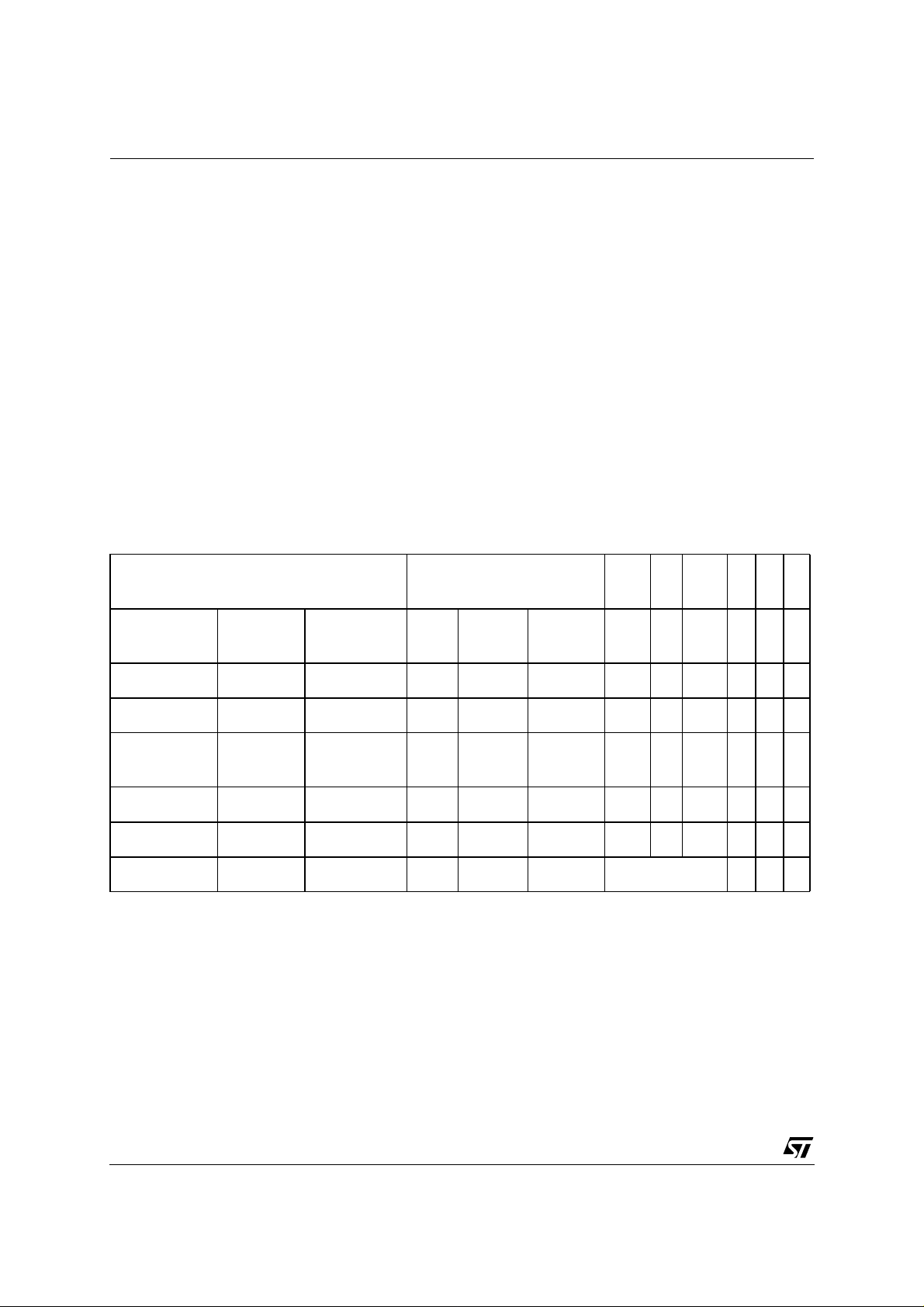
MS bit is set: saturation
mode is enabled
Example: Mov R5,
#5555h
CoLoad R5, R5 00 5555 5555h 0 0 0 0 0 0
Nop 00 5555 5555h 0 0 0 0 0 0
Mov MSW,
#007Fh
Nop 7F 5555 5555h 0 0 0 0 0 0
CoShr #1 3F AAAA AAAAh 0 0 0 0 0 0
Accumulator SL E SV C Z N
-- ---- ----h - - - - - -
7F 5555 5555h 0 0 0 0 0 0
error
In this example, the E flag is kept clear however MAE is used.
Workaround: Disable saturation mode before using Logical and Arithmetic Right Shift in-
structions and re-enable it just after.
2/4
 Loading...