

SGS Thomson Microelectronics SMTPA68, SMTPA100, SMTPA120, SMTPA130, SMTPA180 Datasheet
...
FEATURES
BIDIRECTIONALCROWBAR PROTECTION.
BREAKDOWNVOLTAGERANGE:
From62 V To 270 V.
HOLDINGCURRENT = 150 mA min
REPETITIVEPEAKPULSE CURRENT:
=50 A, 10/1000µs.
I
PP
DESCRIPTION
TheSMTPAxxseries hasbeen designedto protect
telecommunication equipment against lightning
andtransientinducedby AC powerlines.
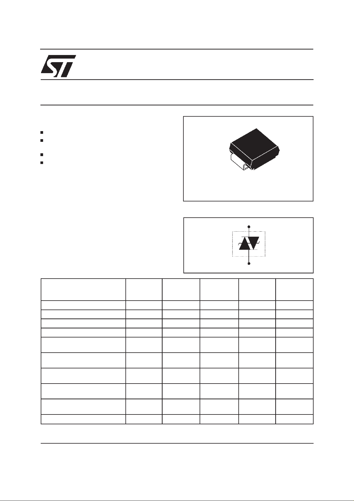
SMTPA SERIES
TRISIL
SMB
(JEDECDO-214AA)
SCHEMATIC DIAGRAM
COMPLIESWITH THE
FOLLOWINGSTANDARDS:
(CCITT)ITU-K20 1000 10/700 5/310 25 (CCITT)ITU-K17
VDE0433
VDE0878 2000 1.2/50 1/20 50 IEC-1000-4-5 level3
FCC Part 68, lightningsurge
type A
FCC Part 68, lightningsurge
type B
BELLCORETR-NWT-001089
Firstlevel
BELLCORETR-NWT-001089
Secondlevel
CNETl31-24 1000 0.5/700 0.8/310 25 -
October 1998- Ed: 7A
PeakSurge
Voltage
(V)
1500 10/700 5/310 38 2000 10/700 5/310 50 -
level4
1500
800
1000 9/720 5/320 25 -
2500
1000
5000 2/10 2/10 150 11.5
Voltage
Waveform
(µs)
10/700
1.2/50
10/160
10/560
2/10
10/1000
Current
Waveform
(µs)
5/310
8/20
10/160
10/560
2/10
10/1000
Admissible
Ipp
(A)
50
100
75
55
150
50
Necessary
Resistor
(Ω)
-
-
12.5
6.5
11.5
10
1/5
SMTPAxxx
ABSOLUTE MAXIMUMRATINGS (T
Symbol Parameter Value Unit
P
I
PP
I
TSM
Powerdissipation
Peakpulse current 10/1000µs
Nonrepetitivesurgepeak on-state
current
dV/dt Criticalrateof rise of off-statevoltage V
T
stg
T
T
Storagetemperaturerange
Maximumjunction temperature
j
Maximumlead temperatureforsoldering during 10 s.
L
THERMAL RESISTANCES
Symbol Parameter Value Unit
Junctionto leads.
(j-l)
R
th
(j-a)
R
th
Junctionto ambienton printedcircuit
withstandardfootprintdimensions.
amb
25°C)
=
T
=50 °C5 W
lead
50
8/20 µs
100
tp= 20ms 30 A
RM
5KV/
- 55to + 150
150
260 °C
20
100 °C/W
A
s
µ
C
°
C
°
C/W
°
ELECTRICALCHARACTERISTICS(T
amb
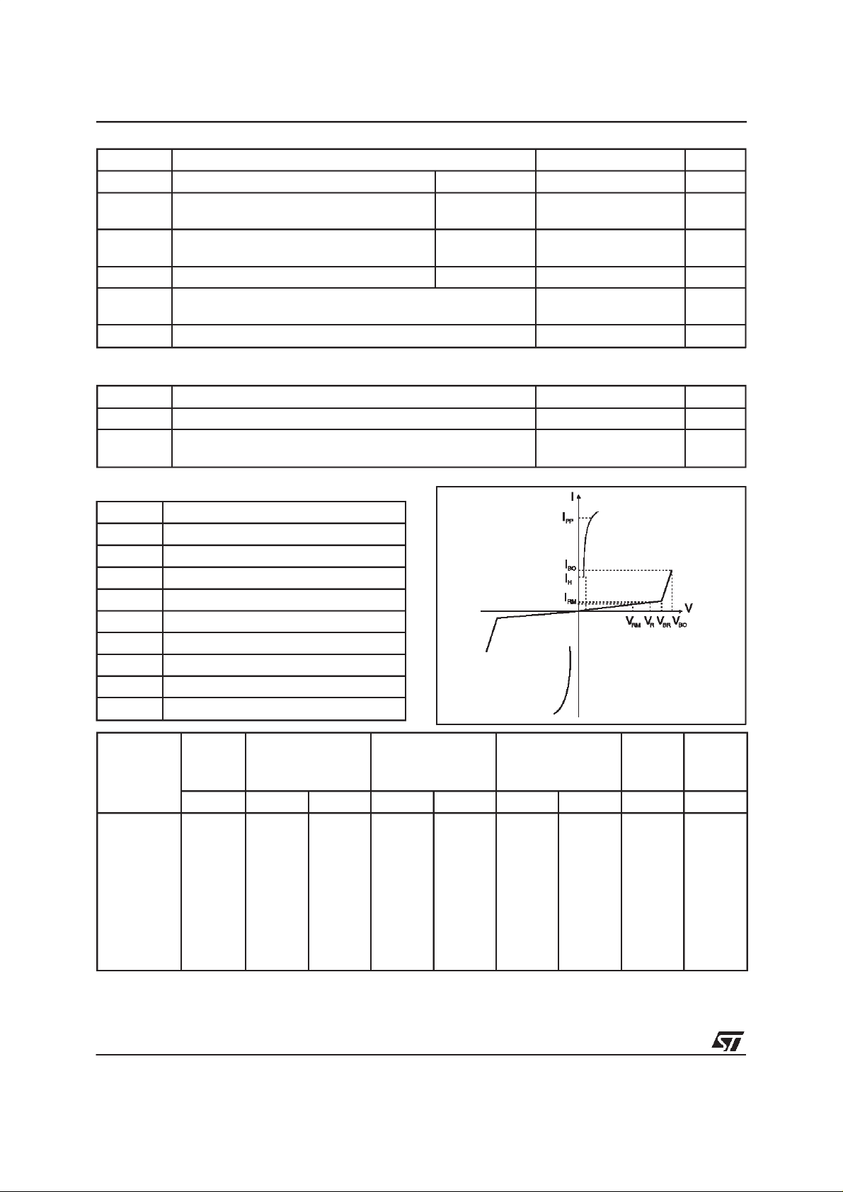
Symbol Parameter
V
RM
I
RM
V
V
BR
V
BO
I
H
I
BO
I
PP
C
Type Marking I
Stand-offvoltage
Leakagecurrentat stand-offvoltage
ContinuousReversevoltage
R
Breakdownvoltage
Breakovervoltage
Holdingcurrent
Breakovercurrent
Peak pulse current
Capacitance
@V
RM
RM
max. max.
Laser
SMTPA62
SMTPA68
SMTPA100
SMTPA120
SMTPA130
SMTPA180
SMTPA200
SMTPA220
SMTPA240
SMTPA270
Allparameters tested at 25°C, except whereindicated.
Note 1: IRmeasured at VRguaranteeV
Note 2: Measured at 50Hz(1 cycle) - See testcircuit 1.
U01
U05
U13
U17
U19
U25
U27
U31
U35
U39
AV
µ
2
2
2
2
2
2
2
2
2
2
BRmin
56
61
90
108
117
162
180
198
216
243
V
≥
R
=25°C)
note 1
IR@V
AV VmAmApF
µ
50
50
50
50
50
50
50
50
50
50
R
62
68
100
120
130
180
200
220
240
270
Note 3: See testcircuit 2.
Note 4: VR= 1V,F = 1MHz. Refer to fig.3 for C versus VR.
VBO@I
max.
note2
82
90
133
160
173
240
267
293
320
360
BO
I
H
max. min.
note3
800
800
800
800
800
800
800
800
800
800
150
150
150
150
150
150
150
150
150
150
C
max.
note4
150
150
100
100
100
100
100
100
100
100
2/5
 Loading...