

SGS Thomson Microelectronics SMP100-270, SMP100-65, SMP100-8, SMP100LC-35, SMP100-120 Datasheet
...
SMP100-xxx
COMMUNICATIONEQUIPMENT PROTECTION: TRISIL
FEATURES
BIDIRECTIONALCROWBARPROTECTION
VOLTAGERANGE: FROM 8V to 270V
REPETITIVEPEAK PULSECURRENT:
= 100 A (10/1000µs)
I
PP
HOLDINGCURRENT: I
LOWLEAKAGECURRENT:I
DESCRIPTION
The SMP100 series are transient surge arrestorsusedfortheprotection of sensitive telecomequipment.
MAINAPPLICATIONS
Any sensitive equipment requiring protection
againstlightningstrikes :
ANALOGAND DIGITALLINE CARDS
MAINDISTRIBUTIONFRAMES
TERMINALSAND TRANSMISSION
EQUIPMENT
GAS-TUBEREPLACEMENT
BENEFITS
= 150mAor 225mA
H
=2µA max
R
SMB
(JEDECDO-214AA)
SCHEMATICDIAGRAM
TM
NOAGEINGAND NO NOISE
IF DESTROYED, THE SMP100 FALLS INTO
SHORTCIRCUIT,STILLENSURINGPROTECTION
BOARDSPACESAVING
COMPLIESWITHTHE
FOLLOWINGSTANDARDS:
ITUK20 4000 10/700 5/310 100 VDE0433 4000 10/700 5/310 100 VDE0878
IEC-1000-4-5
FCCPart 68, lightning surge
type A
FCCPart 68, lightning surge
type B
BELLCORETR-NWT-001089
Firstlevel
BELLCORETR-NWT-001089
Secondlevel
CNETl31-24 4000 0.5/700 0.8/310 100 -
Peak Surge
Voltage
(V)
4000 1.2/50 1/20 100 -
level4
level4
1500
800
100 9/720 5/320 25 -
2500
1000
5000 2/10 2/10 500 -
Voltage
Waveform
(µs)
10/700
1.2/50
10/160
10/560
2/10
10/1000
Current
Waveform
(µs)
5/310
8/20
10/160
10/560
2/10
10/1000
Admissible
Ipp
(A)
100
100
200
100
500
100
Necessary
Resistor
(Ω)
-
-
-
-
-
-
August 1999-Ed : 8A
1/9
SMP100-xxx
THERMAL RESISTANCES
Symbol Parameter Value Unit
R
R
th(j-I)
th(j-a)
Junctionto leads 20 °C/W
Junctionto ambienton printedcircuit
100 °C/W
(withstandardfootprint dimensions)
ABSOLUTE MAXIMUMRATINGS
(T
amb
=
25°C)
Symbol Parameter Value Unit
I
pp
I
FS
I
TSM
T
L
T
stg
Tj
Peakpulse current:
10/1000µs (open circuitvoltagewaveform1 kV 10/1000µs)
5/310µs (opencircuitvoltage waveform4 kV, 10/700µs)
8/20µs (open circuit voltagewaveform4 kV 1.2/50 µs)
2/10µs (opencircuitvoltage waveform2.5kV 2/10 µs)
100
150
250
500
Fail-safemode 8/20 µs5kA
Nonrepetitivesurge peak on-statecurrent
Onecycle
Nonrepetitivesurge peak on-statecurrent
F= 50Hz
50Hz
60Hz
0.2s
2s
55
60
25
12
Maximumlead temperaturefor solderingduring 10s 260 °C
Storagetemperaturerange
Maximumjunction temperature
- 55 to+ 150
150
A
A
A
A
A
A
A
A
°C
°C
Note1:
2/9
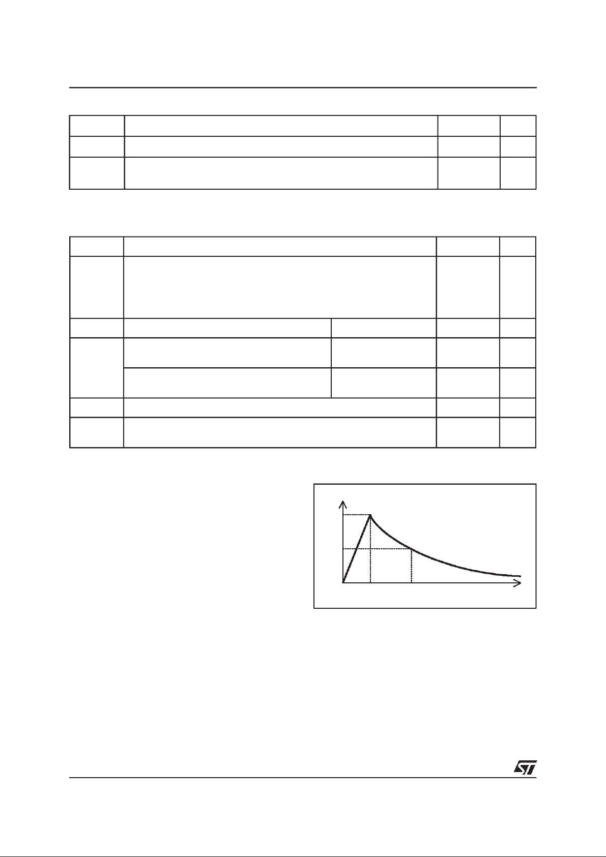
Pulsewaveform
10 / 1000µstr=10µs tp = 1000
µs
8/20µstr=8µstp=20µs
5 / 310µstr=5
1/20µstr=1
µ
s tp = 310µs
µ
stp=20
µ
s
2/10µstr=2µstp=10µs
100
50
0
%I
PP
t
r
t
p
t
SMP100-xxx
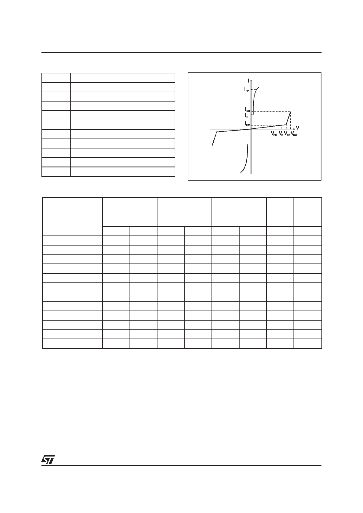
ELECTRICALCHARACTERISTICS(T
amb
=25°C)
Symbol Parameter
V
RM
I
RM
V
R
I
R
V
BR
V
BO
I
H
I
BO
I
PP
C
Stand-offvoltage
Leakagecurrent at stand-offvoltage
Continuousreversevoltage
Continuousreversecurrent
Breakdownvoltage
Breakovervoltage
Holdingcurrent
Breakovercurrent
Peak pulse current
Capacitance
STATICPARAMETERS
Type
@V
I
RM
RM
max.
AV
µ
I
@V
R
R
max.
note 1
AV VmAmApF
µ
V
BO
max.
note 2
@I
BO
I
H
min.
note 3
SMP100-8 2 6 50 8 20 800 50(typ) 100
SMP100LC-35 2 32 50 35 55 800 150 90
SMP100-65 2 55 50 65 80 800 150 160
SMP100-120 2 110 50 120 160 800 150 140
SMP100-140 2 120 50 140 200 800 150 140
SMP100-200 2 170 50 200 265 800 150 130
SMP100-230 2 200 50 230 300 800 150 120
SMP100-270 2 230 50 270 350 800 150 120
SMP100-140H225 2 120 50 140 200 800 225 140
SMP100-200H225 2 170 50 200 265 800 225 130
SMP100-230H225 2 200 50 230 300 800 225 130
SMP100-270H225 2 230 50 270 350 800 225 120
Note 1 : IRmeasured at VRguaranteesVBR>V
Note 2 : Measuredat 50Hz, see testcircuit1. In any caseV
Note 3 : See functional holdingcurrent test circuit 2.
Note 4 : VR=1Vbias, V
=1V,F=1MHz.
RMS
R
BOmin
≥ V
BR
C
typ.
note 4
3/9
 Loading...