

RBO08-40G/M/T
ApplicationSpecificDiscretes
A.S.D.
FEATURES
8ADIODETOGUARDAGAINSTBATTERYREVERSAL.
NEGATIVEOVERVOLTAGEPROTECTIONBY
CLAMPING.
COMPLIANTWITHISO/DTR7637STANDARD
FORPULSES 1, 2,3a and 3b.
SUITABLE FOR AUTOPROTECTED ALTERNATORENVIRONMENT.
BREAKDOWNVOLTAGE: 24V min.
CLAMPINGVOLTAGE:± 40 V max.
MONOLITHIC STRUCTURE FOR GREATER
RELIABILITY.
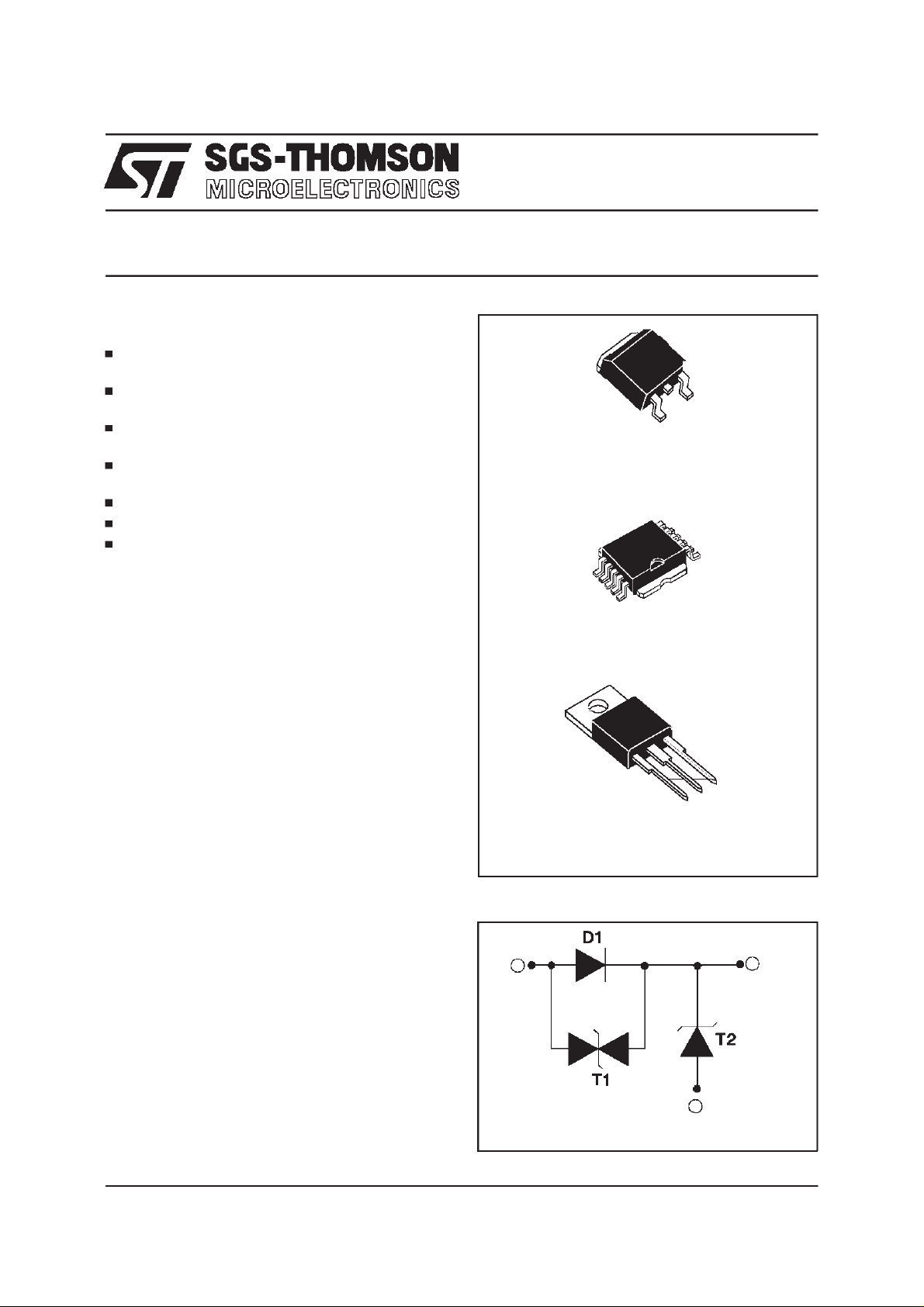
DESCRIPTION
Designedto protectagainstbatteryreversaland
overvoltagesin automotiveapplications,this
monolithiccomponentoffersmultiplefunctionsin
the samepackage:
D1 : reversedbattery protection
T1 : clampingagainst negativeovervoltages
T2 : Transilfunctionfor overvoltageprotection.
TM
OVERVOL TAGEPROTECT IONCIRCUI T (RBO)
REVERSEDBATTERYAND
D2PAK
RBO08-40G
PowerSO-10
RBO08-40M
TM
January1998 - Ed : 2
TO220AB
RBO08-40T
FUNCTIONAL DIAGRAM
1
3
2
1/14
RBO08-40G / RBO08-40M / RBO08-40T
ABSOLUTE MAXIMUM RATINGS
Symbol Parameter Value Unit
I
FSM
Non repetitivesurgepeak forward current
tp = 10 ms 80 A
(DiodeD1)
I
F
P
PP
DC forwardcurrent(Diode D1) Tc = 75°C8 A
PeakpulsepowerbetweenInput andOutput
10/1000µs 600 W
(TransilT1) seenote 1 Tjinitial= 25°C
P
PP
T
stg
Tj
T
L
PeakpulsepowerbetweenPins 3 and 2 (10/1000µs) 1500 W
Storagetemperature range
Maximumjunction temperature
Maximumlead temperaturefor solderingduring 10 s
- 40 to+ 150
150
260 °C
at 4.5mm from case for TO220AB
Note 1 : for a surge greater than themaximum value, thedevice will fail inshort-circuit..
TM :PowerSO-10,TRANSIL and ASD are trademarks ofSGS-THOMSON Microelectronics.
THERMAL RESISTANCE
Symbol Parameter Value Unit
Rth (j-c)
Junctionto case
RBO08-40M
RBO08-40G
RBO08-40T
2.4
2.4
2.4
°C
°C/W
2/14
D1
T1
V
V
31 VRM31
CL
I13
31
F
I
T2
2
31
BR
V
IRM31
31
I
R
Ipp31
F13
V13
Ipp32
I
RM
I32
IR32
32
VRM32 V
32 V
R
B
1
V32
32
C
L
3
2

RBO08-40G / RBO08-40M / RBO08-40T
Symbol Parameter
V
RM31/VRM32
V
BR31/VBR32
I
R31/IR32
V
CL31/VCL32
V
F13
I
PP
αT
C
31/C32
Stand-offvoltage Transil T1 / TransilT2.
Breakdownvoltage TransilT1 / TransilT2.
LeakagecurrentTransil T1 / TransilT2.
ClampingvoltageTransil T1 / TransilT2.
Forwardvoltagedrop DiodeD1.
Peak pulsecurrent.
Temperaturecoefficientof V
BR
.
CapacitanceTransil T1 / TransilT2.
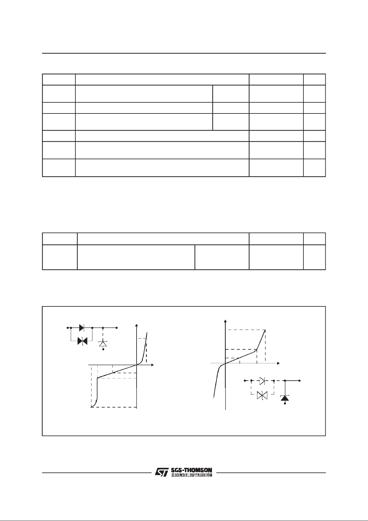
ELECTRICAL CHARACTERISTICS: DIODED1 (- 40°C< T
amb
Symbol Test Conditions
V
F13
IF=8A
RBO08-40M/G
RBO08-40T
V
F13
=8A@T
I
F
IF=4A
=25°C 1.45 V
amb
RBO08-40M/G
RBO08-40T
I
V
F13
=4A@T
F
IF= 1A 1.1 V
I
=1A@T
F
= 1A@ Tj= 85°C 0.9 V
I
F
=25°C
amb
=25°C 1.0 V
amb
ELECTRICAL CHARACTERISTICS: TRANSIL T1 (- 40°C<T
Symbol Test Conditions
V
BR 31
V
BR 31
I
RM31
I
RM31
V
CL31
αT TemperaturecoefficientofV
C
31
IR=1 mA 22 35 V
IR=1 mA, T
=25°C2432V
amb
VRM=20V 50 µA
VRM=20V,T
IPP=15A,Tjinitial=25°C
amb
=25°C
10/1000µs40V
BR
F = 1MHz VR= 0 V 1000 pF
<+85°C)
<+85°C)
amb
Value
Min. Typ. Max.
1.5 V
1.7 V
1.3 V
1.35 V
1.2 V
Value
Min. Typ. Max.
10 µA
910-4/°C
Unit
Unit
ELECTRICAL CHARACTERISTICS: TRANSIL T2 (- 40°C<T
Symbol Test Conditions
V
BR 32
V
BR 32
I
RM 32
I
RM 32
V
CL 32
αT
C
32
IR=1 mA 22 35 V
IR=1 mA, T
=25°C2432V
amb
VRM=20V 50 µA
VRM=20V,T
IPP= 37.5 A
Temperaturecoefficientof V
=25°C10µA
amb
10/1000µs40V
BR
F = 1MHz VR=0 V 2000 pF
amb
<+85°C)
Value
Min. Typ. Max.
Unit
8.5 10-4/°C
3/14
RBO08-40G / RBO08-40M / RBO08-40T
PRODUCTDESCRIPTION
1
2
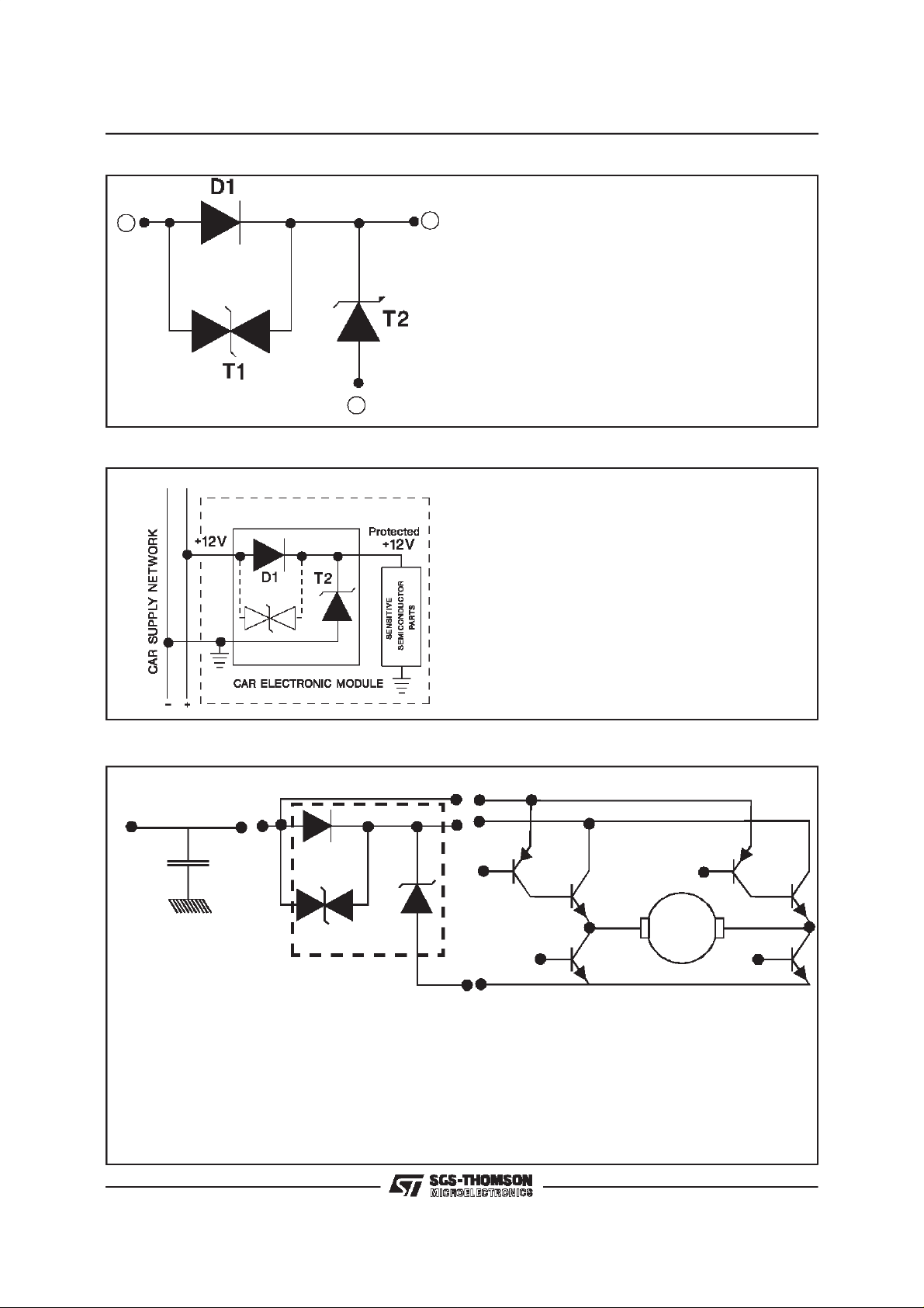
BASICAPPLICATION
TheRBO has 3 functionsintegratedon thesame
3
chip.
D1 : “Diode function”in order to protect against
reversedbattery operation.
T2:“Transil function” in order to protect against
positive surge generated by electric systems
(ignition, relay. ...).
T1 : Protection againt negative surges such as
inductive overvoltages (see motor application
below).
* The monolithic multi-function protection
(RBO) has been developed to protect
sensitivesemiconductorsin car e lect ronic
modules against both overvoltage and
batteryreverse.
* In addition, the RBO circuit prevents
overvoltages generated by the module from
affecting the carsupply network.
MOTORDRIVER APPLICATION
BATTERY
Filter
D1
T2
T1
MOTOR
RBO
DEVICE MOTOR CONTROL
In thisapplication,onehalfofthemotordrivecircuitis suppliedthroughthe “RBO”and isthusprotected
as per its basic function application.
The secondpart is connecteddirectlyto the “carsupplynetwork” andis protectedas follows:
- Forpositive surges: T2 (clampingphase) and D1 in forward-biased.
- Fornegative surges: T1(clampingphase) and T2 inforward-biased.
4/14
2
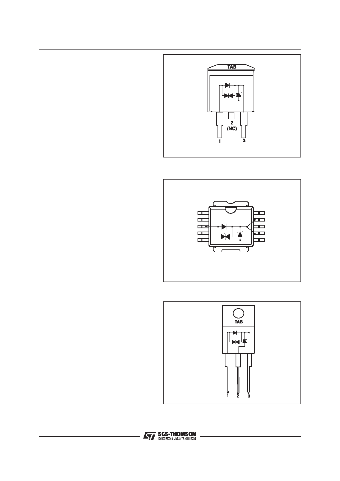
PINOUTconfigurationin D
PAK:
-Input (1) : Pin1
-Output (3) : Pin3
-Gnd (2) : Connectedto base Tab
Marking : Logo, datecode, RBO08-40G
PINOUTconfigurationin PowerSO-10:
-Input (1) : Pin3
-Output (3) : Pin7 and9
-Gnd (2) : Connectedto base Tab
Marking : Logo, datecode, RBO08-40M
RBO08-40G / RBO08-40M / RBO08-40T
D1
T2
T1
TAB
Pin 1 (NC)
Pin 2 (NC)
Pin 3 (Input 1)
Pin 4 (NC)
Pin 5 (NC)
Input (1)
D1
Output(3)
T2
T1
Gnd (2)
Tab
Pin 10(NC)
Pin 9 (Ouput 3)
Pin 8 (NC)
Pin 7 (Ouput 3)
Pin 6 (NC)
PINOUTconfigurationin TO220AB:
-Input (1) : Pin1
-Output (3) : Pin3
-GND (2) : Connectedto base Tab
Marking : Logo, datecode, RBO08-40T
TOP VIEW
D1
T2
T1
(TAB)
5/14
 Loading...