


2A QUAD DAR LINGTON SWITC H
SUSTAINING VOLTAGE: 70 V
2 A OUTPUT
HIGH CURRENT GAIN
IDEAL FOR DRIVING SOLENOIDS, DC
MOTORS, STEPPER MOTORS, RELAYS,
DISPLAYS, ETC.
DESCRIPTION
The L702 is a monolithic integrated circuit for high
current and high voltage switching applications. It
comprises four darlingt on transist ors with commo n
emitter and open collector suitable for current s inking applications mounted on the new POWERDIP
and Multiwatt® packages.
This circuit reduces co mponents, sizes and costs;
it can provide direct interface between low level
logic and a variety of high current applications.
L702
Multiwatt-11
Powerdip 8 + 8
ORDER CODES : L702B - Powerdip
L702N - Multiwatt
ABSOLUTE MAXIMUM RATINGS
Symbol Parameter Value Unit
V
P
T
October 1991
Collector-emitter Voltage (input open) 90 V
CEX
V
Input Voltage 30 V
i
I
Collector Current 3 A
C
Total Power Dissipation at T
tot
Total Power Dissipation at T
Total Power Dissipationa t T
Storage Temperature -55 to 150
stg
Operating Junction Temperature -25 to 150
T
j
9 to 16 ≤ 90 °C
pin
≤ 70 °C
amb
≤ 90 °C
case
}
Powerdip
Multiwatt 20 W
4W
1.1 W
°C
°C
1/7
L702
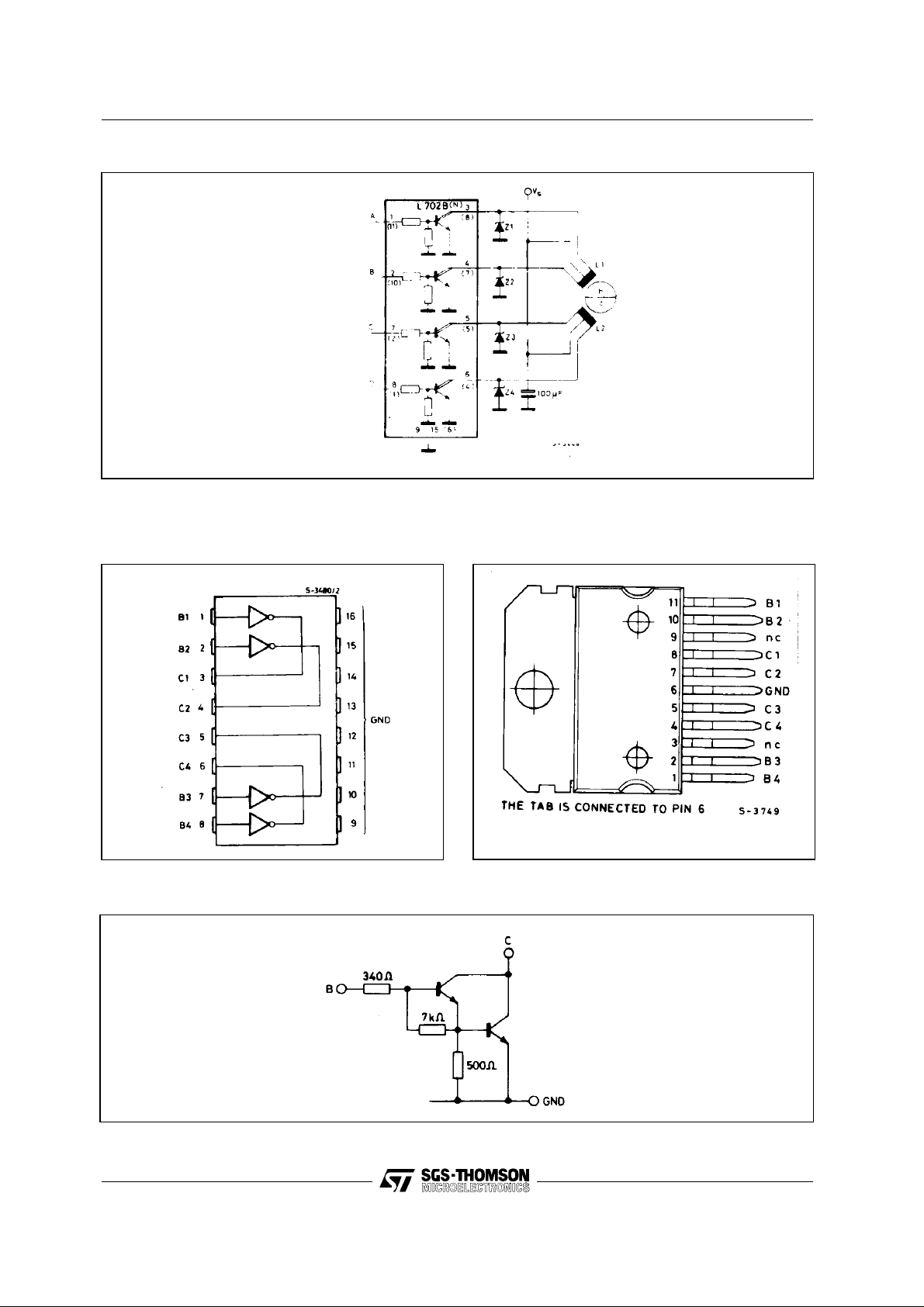
STEPPING MOTOR BUFFER
CONNECT IO N DIAG RA MS (top view)
Powerdip Multiwatt
SCHEMATIC DIAGRAM (each Darlingt on)
2/7

THERMAL DATA
Symbol Parameter Value Unit
R
th j-amb
R
th j-pins 9/16
R
th j-case
Thermal Resistance Junction Ambient
}
Powerdip
Thermal Resistance Junction Pins 9 to 16 Max 14
Thermal Resistance Junction-case Multiwatt Max 3
Max 70
L702
°C/W
°C/W
°C/W
ELECTRICAL CHARACTERISTICS (T
= 25°C unless otherwise specified)
case
Symbol Parameter Test conditions Min. Typ. Max. Unit
I
CEX
V
CE(sust)
V
CE(sat)
h
Output Leakage Current VCE = 90 V 10 50
Collector Emitter (°) Sustaining
Voltage
Collector Emitter Saturation
Voltage
DC Forward Current Gain IC = 1 A
FE
I
Input Current Vi = 3.75 V
i
= 100 mA
I
C
IC = 1.25 A
= 2 mA
I
i
= 3 V
V
CE
V
= 2.4 V
i
70
1.000 4.000
1.3 1.9 V
7
3
11
6
Open Collector
Input Voltage Off Condition VCE = 70 V
V
i
On Condition V
T
T
Turn On Time Vs = 12 V 0.3
on
Turn Off Time
off
CE
= 10 Ω
R
L
= 3 V
≤ 0.1 mA
I
C
≥ 1 A
I
C
1
0.4 V
2.4 V
µA
V
mA
mA
µs
µs
Figure 1. Switching Time. Figure 2. ton and t
Test Circuit.
off
3/7

L702
Figure 3. Peak Collector Current
vs. Duty Cycle and Number of
Outputs (L702B o nl y)
Figure 5. Collector Current vs.
Input Voltage.
Figure 4. Collector Emitter
Saturation Voltage vs. Collector
Current.
Figure 6. Input Current vs. Input
Voltage.
Figure 7. Safe Operating Areas
(L702B).
4/7
Figure 8. Safe Operating Areas
(L702N).

MULTIW ATT1 1 PACKAGE MECHANICAL DATA
DIM.
MIN. TYP. MAX. MIN. TYP. MAX.
A 5 0.197
B 2.65 0.104
C 1.6 0.063
D 1 0.039
E 0.49 0.55 0.019 0.022
F 0.88 0.95 0.035 0.037
G 1.57 1.7 1.83 0.062 0.067 0.072
G1 16.87 17 17.13 0.664 0.669 0.674
H1 19.6 0.772
H2 20.2 0.795
L 21.5 22.3 0.846 0.878
L1 21.4 22.2 0.843 0.874
L2 17.4 18.1 0.685 0.713
L3 17.25 17.5 17.75 0.679 0.689 0.699
L4 10.3 10.7 10.9 0.406 0.421 0.429
L7 2.65 2.9 0.104 0.114
M 4.1 4.3 4.5 0.161 0.169 0.177
M1 4.88 5.08 5.3 0.192 0.200 0.209
S 1.9 2.6 0.075 0.102
S1 1.9 2.6 0.075 0.102
Dia1 3.65 3.85 0.144 0.152
mm inch
L702
5/7

L702
POWERDIP PACKAGE MECHANICAL DAT A
DIM.
MIN. TYP. MAX. MIN. TYP. MAX.
a1 0.51 0.020
B 0.85 1.40 0.033 0.055
b 0.50 0.020
b1 0.38 0.50 0.015 0.020
D 20.0 0.787
E 8.80 0.346
e 2.54 0.100
e3 17.78 0.700
F 7.10 0.280
I 5.10 0.201
L 3.30 0.130
Z 1.27 0.050
mm inch
6/7

L702
Information furnished is believed to be accurate and reliable. However, SGS-THOMSON Microelectronics assumes no responsibility for the
consequences of use of such information nor for any infringement o f patents or other rights of third parties which may result from its use. No
license is granted by implicat ion o r otherwise under any patent or patent rights of SGS-THOMSON Microelectronics. Specifications mentioned
in this publication are subject to change without notice. This publication supersedes and replaces all information previously supplied.
SGS-THOMSON Microelectronics products are not a uthorized for use as critical components in life support devices or systems without ex press
written approval of SGS-THOMSON Microelectronics.
© 1994 SGS-THOMSON Microelectronics - All Rights Reserved
SGS-THOMSO N Microelec tronics G ROUP OF COMPANIES
Australia - Brazil - France - Germany - Hong Kong - Italy - Japan - Korea - Malaysia - Malta - Morocco - The Netherlands - Singapore -
Spain - Sweden - Switzerland - Taiwan - Thaliand - United Kingdom - U.S.A.
7/7
 Loading...