

CAR ALTERNATOR REGULATOR
.ALTERNATORVOLTAGECONTROL
.COMPLETEFAULT DIAGNOSTICS
.DRIVES3 W LAMP DIRECTLY
.LAMPSHORTCIRCUIT PROTECTION
.SENSINGINTERRUPT PROTECTION
.100V DUMPPROTECTION
.300V LOW ENERGY SPIKEPROTECTION
.THERMALPROTECTION
DESCRIPTION
The L585 is an integratedcircuit designedfor use
with an NPN darlingtonas a voltage regulatorin a
threephasealternator charging system. It includes
faultdiagnosticcircuitrywhichdrivesa3Wwarning
lampinfaultconditionssuchasopenor shortcircuit
connections. Protection against load dump transients,shortcircuits andlowenergyspikesisincorporated.
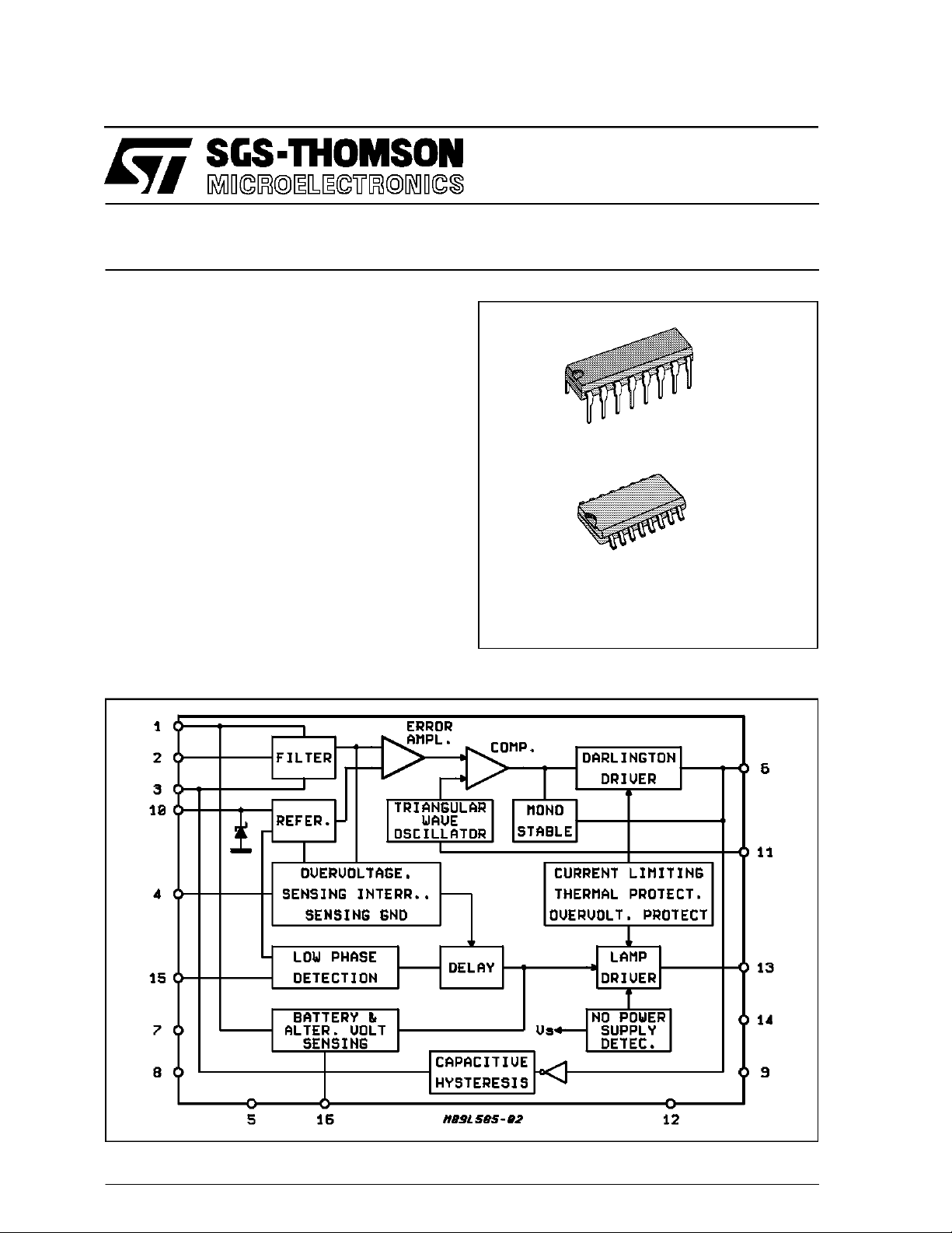
L585
DIP16
SO16
ORDERING NUMBERS : L585(DIP16)
L585D1 (SO16)
BLOCK DIAGRAM
November 1991
1/9
L585
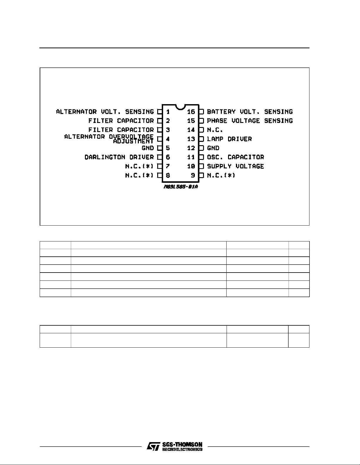
PI N CONNECTI ON
(*) MUST BE LEFT FLOATING
ABSOLUTE MAXIMUM RATINGS
Symbol Parameter Value Unit
V
V
T
P
T
stg
T
Operating supply Voltage (through RS)28V
S
Dump Voltage 100 V
D
Junction Temperature Range – 40 to 150 °
j
Power Dissipation at T
tot
amb
=80°C
1W
Junction and Storage Temperature Range – 55 to 150 °
Operating Temperature Range – 40 to 125 °
op
C
C
C
THERMAL DATA
Symbol Parameter Value Unit
R
th j-amb
R
th j-alumina
Note : Soldered on PC board that simulatesan application with medium device density onboard.
(*) Thermalresistance junction-pins withthe chipsoldered onthe middleof an aluminasupporting substrate measuring 15 ö 20 mm ; 0.65 mm
thickness and infinite heathsink.
Thermal Resistance Junction-ambient (*) for DIP 16
(*)
Thermal Resistance Junction-alumina for SO-16
Max
Max
80
50
°C/W
°C/W
2/9
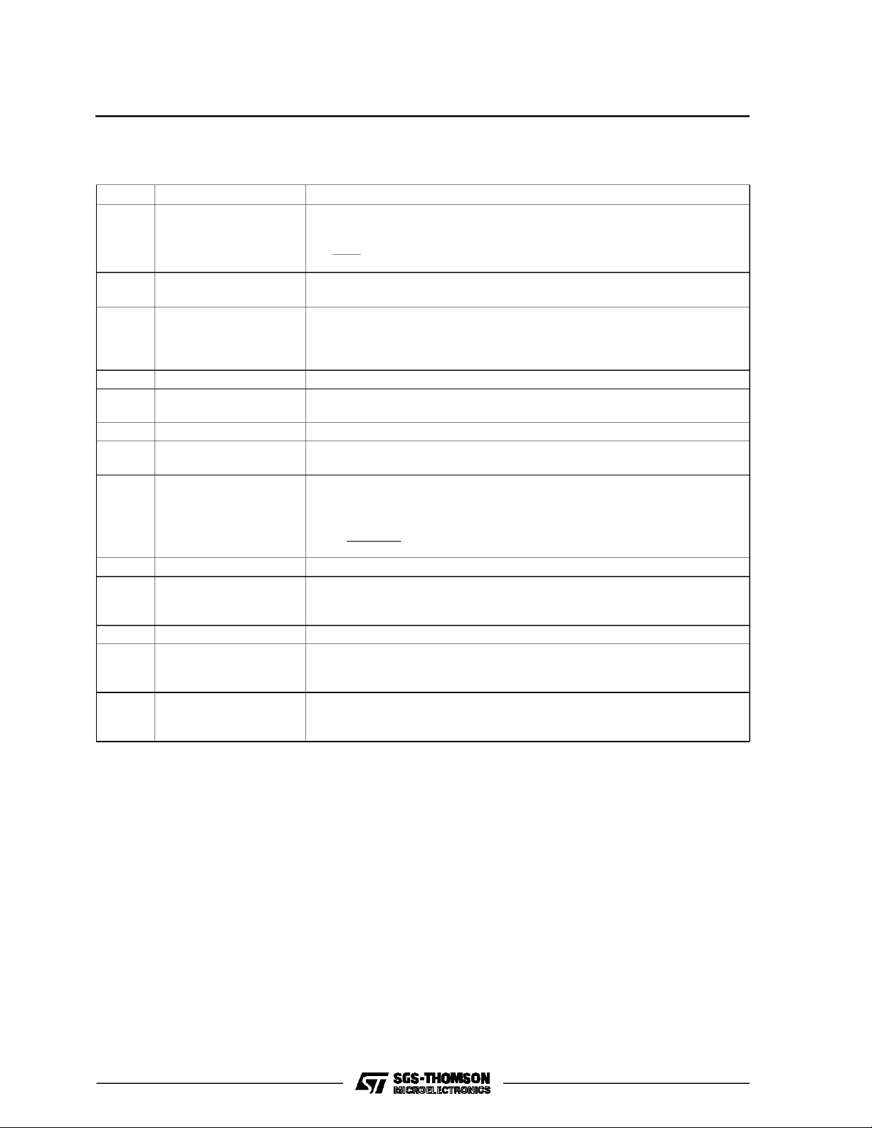
PIN FUNCTIONS
N° Name Functions
1 Alternator Voltage
Sensing
2-3 Filter Capacitor A capacitor connected between these two pins filters the feedback signal from
4 Alternator Overvoltage
Adjustment
5 GND This pin must be connected to ground.
6 Darlington Driver This pin drives the external darlington disabling it by shorting the current in R
7-8-9 N.C. These pins must be left floating.
10 IC Supply Voltage Supply Voltage Input
11 Oscillator Capacitor A capacitor connected to ground sets the frequency of the internal oscillator.
Connection for voltage regulation sensing. The regulation sensitivity is a
function of R1 and is given by :
∆VA
S=
∆ R1
= 0.5mV⁄ Ω
the regulated output. Typically the input impedance is 15KΩ.
When this pin is left open circuit the overvoltage threshold is a described in the
specification. Typically the warning lamp is switched on when the voltage at
this pin is greater than 3.5V. This threshold can be modified with a resistor
between either the ground or pin 2.
to ground.
A 7.5V (typical) Zener is present at the input.
The frequency is given by :
L585
B
−6
20 x 10
fosc =
8.4 x C
osc
12 GND This pin must be connected to ground.
13 Lamp Driver Current Driver for External Lamp for Diagnostics.
Internally protected agains short circuits (current limiting), load dump transients
and, by means of a zener, against low energy spikes.
14 NC Not connected.
15 Phase Voltage Sensing. Connection for no charge sensing from the alternator .
The internal low threshold is typically 2.4V. By means of the external divider
R3/R4 the threshold can be adjusted to give the required sensitivity.
16 Battery Voltage Sensing Connection for Voltage Battery Sensing
This pin senses a failure of the alternator-battery lead as the voltage difference
. The external resistor R2 limits the current in overvoltage protection.
V
A-VS
3/9
 Loading...