

L297
L297A
STEPPER MOTOR CONTROLLERS
NORMAL/WAWEDRIVE
HALF/FULLSTEP MODES
CLOCKWISE/ANTICLOCKWISEDIRECTION
SWITCHMODE LOAD CURRENT REGULA-
TION
PROGRAMMABLE LOAD CURRENT
FEWEXTERNALCOMPONENTS
RESETINPUT& HOME OUTPUT
ENABLEINPUT
STEP-PULSEDOUBLER(L297Aonly)
DESCRIPTION
The L297 Stepper Motor Controller IC generates
fourphase drivesignals for two phase bipolar and
fourphaseunipolar stepmotorsinmicrocomputercontrolledapplications.The motor can be driven in
half step, normal and wawe drive modes and onchip PWM chopper circuits permit switch-mode
control of thecurrent in the windings. A feature of
October 1991
Symbol Parameter Value Unit
V
s
Supply voltage 10 V
V
i
Input signals 7V
P
tot
Totalpower dissipation (T
amb
=70°C)
1W
T
stg,Tj
Storage and junction temperature -40 to + 150 °C
ABSOLUTEMAXIMUM RATINGS
this device is that it requires only clock, direction
and mode input signals. Sincethe phaseare generated internallytheburdenonthemicroprocessor,
and the programmer,is greatly reduced. Mounted
in a 20-pin plastic package, the L297 canbe used
with monolithicbridge drivessuch asthe L298N or
L293E, orwith discretetransistorsanddarlingtons.
The L297Aalso includesa clock pulse doubler.
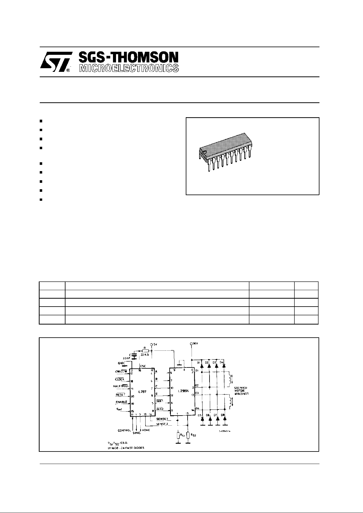
TWOPHASE BIPOLAR STEPPER MOTOR CONTROL CIRCUIT
DIP-20 Plastic
(0.25)
ORDER CODES : L297 - L297A
1/11
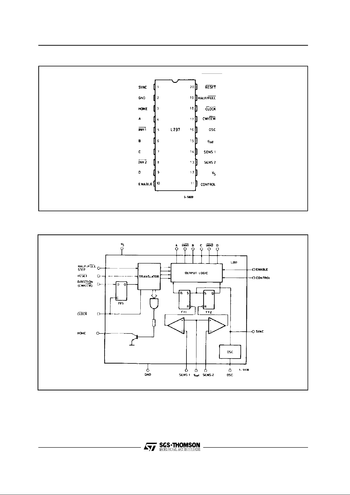
PIN CONNECTION (L297)
BLOCK DIAGRAM (L297)
2/11
L297-L297A
Symbol Parameter Value Unit
Rth-j-amb Thermal resistance junction-ambient max 80 °C/W
THERMALDATA
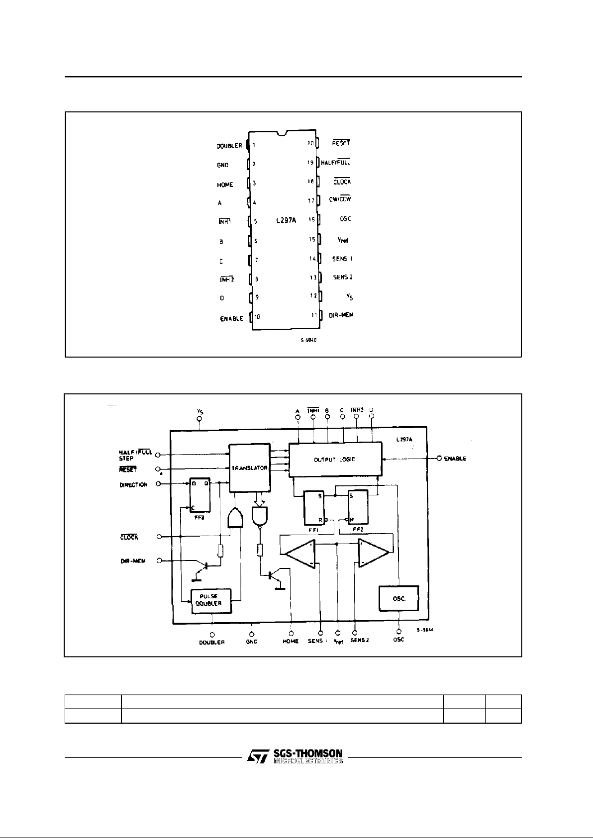
BLOCK DIAGRAM (L297A)
PIN CONNECTION (L297A)
3/11
L297-L297A
4/11
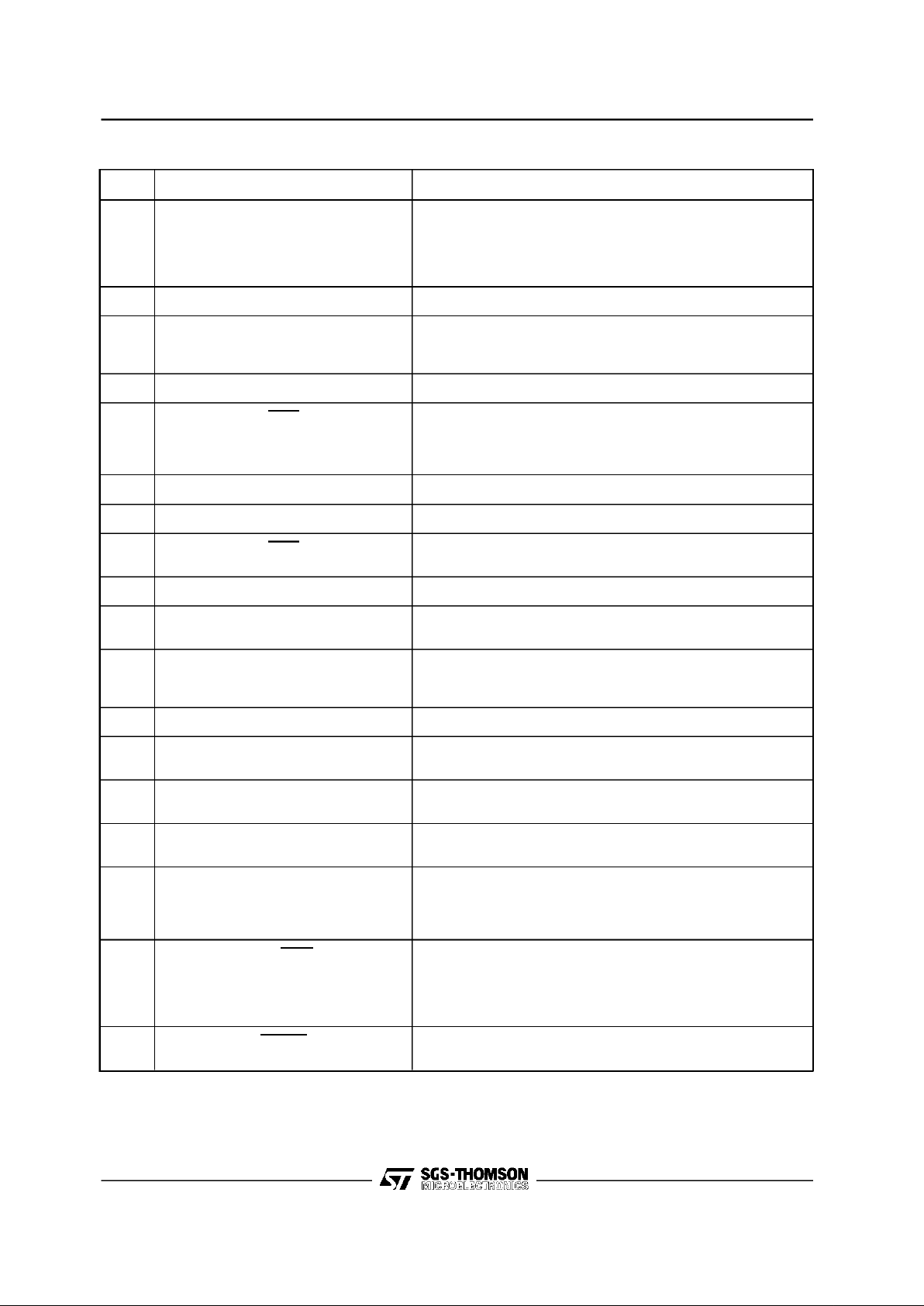
N°
NAME FUNCTION
1 SYNC Output of the on-chip chopper oscillator.
TheSYNC connections The SYNC connections of all L297s to be
synchronized are connected together and the oscillator
componentsare omitted on all but one. If an external clock
source is used it is injected at this terminal.
2 GND Ground connection.
3 HOME Open collector output that indicates when the L297 is in itsinitial
state (ABCD = 0101).
Thetransistor is open when this signal is active.
4 A Motor phase Adrive signal for power stage.
5 INH1 Activelow inhibit control for driverstage of Aand B phases.
When a bipolar bridge isused this signal can be used to ensure
fast decay of load current when a winding is de-energized. Also
used by chopper to regulate load current if CONTROL input is low.
6 B Motor phase B drive signal for power stage.
7 C Motorphase C drive signal for power stage.
8 INH2 Activelow inhibit control for drive stages of C and D phases.
Same functions as INH1.
9 D Motorphase D drive signal for power stage.
10 ENABLE Chipenable input. When low (inactive) INH1, INH2, A, B,C and D
are brought low.
11 CONTROL Controlinput that defines action of chopper.
When low chopper acts on INH1 and INH2;when high chopper
acts on phase lines ABCD.
12 V
s
5Vsupply input.
13 SENS
2
Inputfor load current sense voltage from power stagesof phases
C and D.
14 SENS
1
Inputfor load current sense voltage from power stagesof phases
Aand B.
15 V
ref
Reference voltage for chopper circuit. Avoltage applied to this pin
determinesthe peak load current.
16 OSC
AnRC network (R to V
CC
, C to ground) connected to this terminal
determinesthe chopper rate. This terminal is connected to
groundon all but one device in synchronized multi - L297
configurations. f ≅ 1/0.69 RC
17 CW/CCW Clockwise/counterclockwise direction control input.
Physical direction of motor rotation also depends on connection
of windings.
Synchronized internally therefore direction can be changed at any
time.
18 CLOCK Stepclock. An activelow pulse on this input advances the motor
one increment. The step occurs on the rising edge of this signal.
PIN FUNCTIONS - L297
L297-L297A
 Loading...