

LOWDROPDUAL POWER OPERATIONALAMPLIFIERS
.OUTPUTCURRENT TO 1A
.OPERATESATLOW VOLTAGES
.SINGLEOR SPLIT SUPPLY
.LARGE COMMON-MODE AND DIFFEREN-
TIALMODERANGE
.LOW INPUT OFFSETVOLTAGE
.GROUNDCOMPATIBLEINPUTS
.LOW SATURATIONVOLTAGE
.THERMAL SHUTDOWN
.CLAMPDIODE
DESCRIP T IO N
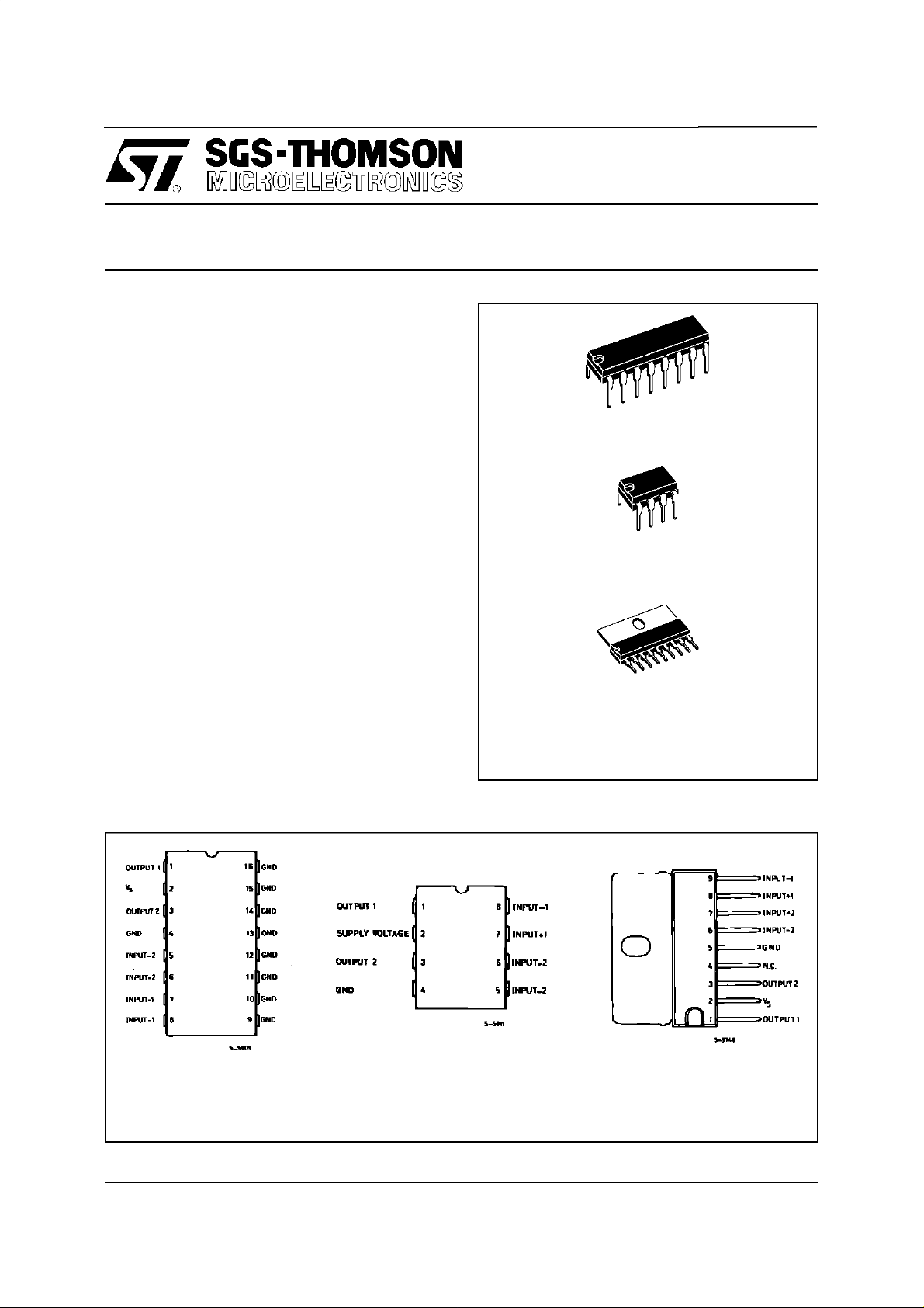
The L2720, L2722 and L2724 are monolithic integratedcircuitsin powerdip, minidipandSIP-9packages,intendedforuse as poweroperationalamplifiersin a widerangeof applicationsincludingservo
amplifiers and power supplies.
Theyare particularlyindicatedfordriving, inductive
loads,as motor and finds applicationsin compactdiscVCR automotive,etc.
Thehighgain and highoutputpowercapabilityprovidesuperior performancewhateveranoperational
amplifier/powerboostercombinationis required.
L2720/2/4
PO W E RDIP
(8+ 8)
MINIDI P
(Plastic)
SIP9
ORDERING NUMBERS : L2720(Powerdip)
L2722(Minidip)
L2724(SIP9)
PI N CO NNECT IONS (top views)
L2720 L2722 L2724
November1996
1/10
L2720/2/4
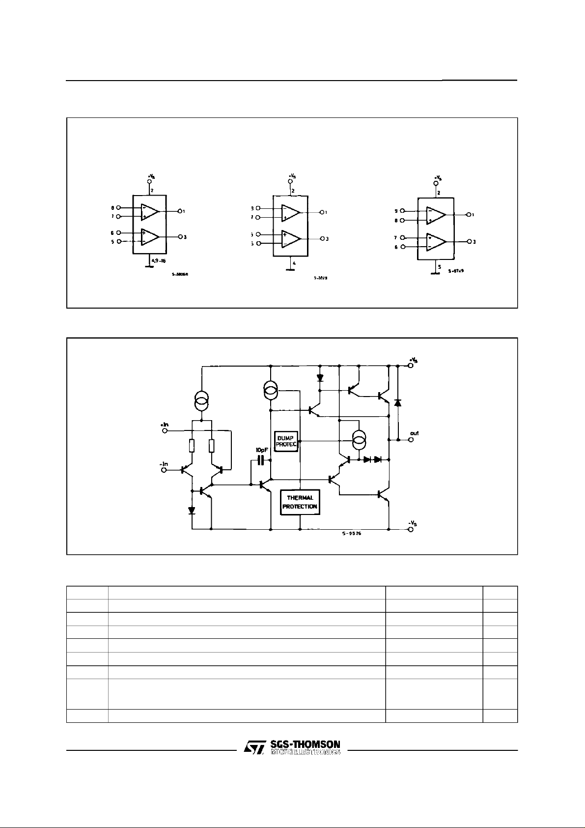
BLOCK DI AGRAM
L2720 L2722 L2724
SCHEMATIC DIAGRAM (one section)
ABSOLUTE MAXIMUM RATINGS
Symbol Parameter Value Unit
Supply Voltage 28 V
S
Peak Supply Voltage (50ms) 50 V
S
Input Voltage V
V
i
V
Differential Input Voltage
i
I
DC Output Current 1 A
o
Peak Output Current (non repetitive) 1.5 A
I
p
Power Dissipation at T
tot
=80oC (L2720), T
amb
=75oC (L2720)
T
case
=50oC (L2724)
T
case
=50oC (L2722)
amb
s
±V
1
5
10
Storage and Junction Temperature –40 to 150
s
T
2/10
V
V
P
stg,Tj
W
o
C
L2720/2/4
THERMAL DATA
SIP-9 Powerdip Minidip
R
th j-case
R
th j-amb
ELECTRICAL CHARACTERISTICS
= 24V, T
V
s
Symbol Parameter Test Conditions Min. Typ. Max. Unit
CMR Common Mode Rejection f = 1kHz 66 84 dB
V
DROP(HIGH)
V
DROP(LOW) V
Thermal Resistance Junction-case Max. 10oC/W 15oC/W 70oC/W
Thermal Resistance Junction-ambient Max. 70oC/W 70oC/W 100oC/W
= 25oC unless otherwise specified
amb
V
s
V
s
I
s
I
b
V
os
I
os
Single Supply Voltage 4 28 V
Split Supply Voltage
Quiescent Drain Current
V
s
V
=
o
2
V
= 24V
s
V
=8V 9 15
s
± 2 ± 14
10 15
Input Bias Current 0.2 1
Input Offset Voltage 10 mV
Input Offset Current 100 nA
SR Slew Rate 2
B Gain-bandwidth Product 1.2 MHz
R
G
v
e
N
I
N
SVR Supply Voltage Rejection f = 100Hz V
C
s
T
sd
Input Resistance 500
i
O.L. Voltage Gain f = 100Hz
f = 1kHz
Input Noise Voltage
Input Noise Voltage 200 pA
B = 22Hz to 22kHz
R
= 10kΩ Vs= ±12V
G
V
= 0.5V Vs= ±6V
R
= 24V
s
Vs= ±2.5V to ±12V Ip= 100mA
= 500mA
I
p
= ±2.5V to ±12V Ip= 100mA
s
= 500mA
I
p
Channel Separation f = 1KHz Vs= 24V
R
=10Ω Vs=6V
L
= 30dB
G
v
70 80
60
10
70
60
75
80
0.7
0.3
0.5 1
60
60
1 1.5
Thermal Shutdown Junction
Temperature 145
V
mA
µA
V/µs
kΩ
dB
µV
dB
V
V
dB
o
C
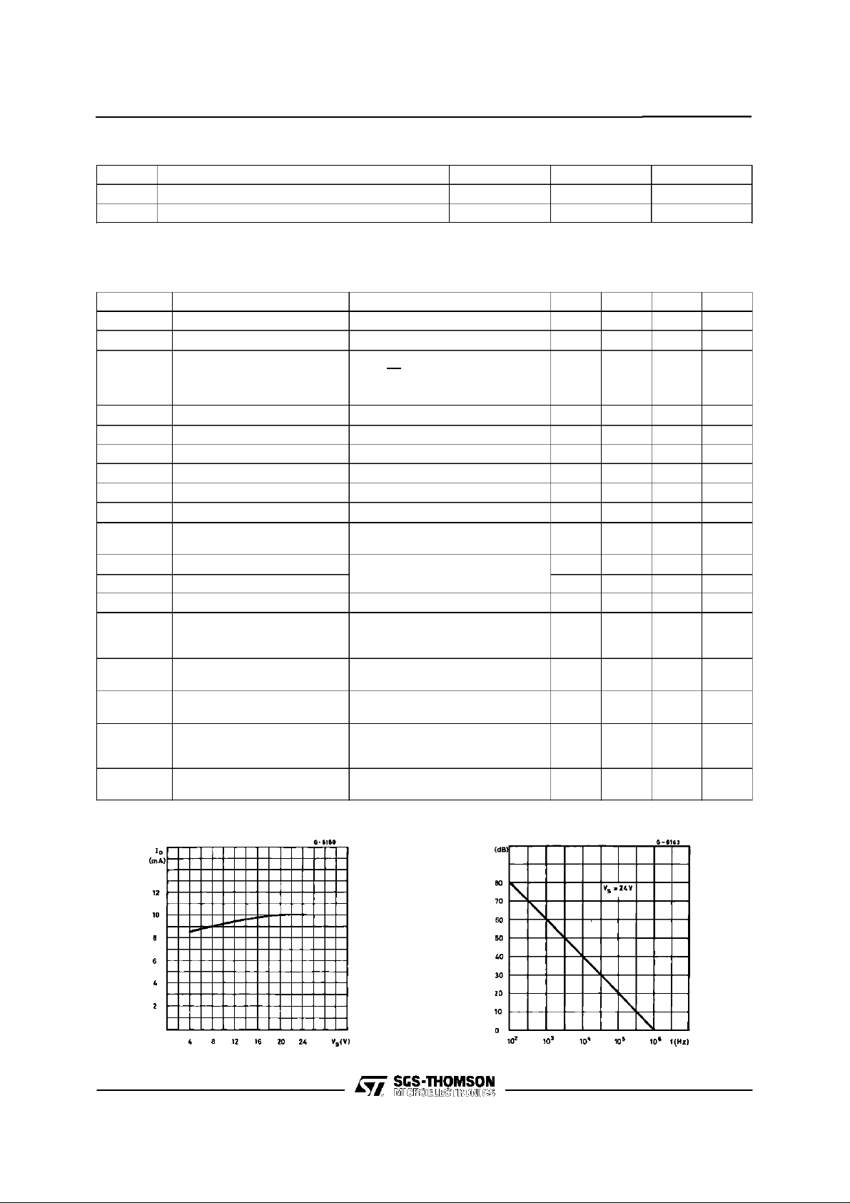
Figure1 : QuiescentCurrent vs. Supply Voltage FIgure 2 : Open Loop Gain vs. Frequency
3/10

L2720/2/4
Figure3 : CommonModeRejection vs.
Frequency
Figure5 : OutputSwingvs. LoadCurrent
=± 12 V.
(V
S
Figure 4 : OutputSwingvs. LoadCurrent
(V
= ± 5V.
S
Figure 6 : SupplyVoltagerejection vs.
Frequency
Figure7 : ChannelSeparation vs.
Frequency
4/10

L2720/2/4
APPLICATIONSUGGESTION
In orderto avoid possibleinstabilityoccuringintofinalstagetheusualsuggestionsforthelinearpower
stagesare useful, as for instance:
layoutaccuracy;
-
A100nFcapacitorconnectedbetweensupply
-
pins and ground ;
Figure8 : BidirectionalDC Motor Controlwith µP Compatible Inputs
Figure9 : Servocontrolfor Compact-disc Figure10 : Capstan Motor Controlin Video
boucherotcell(0.1to0.2 µF+1Ωseries)be-
-
tweenoutputsandgroundoracross theload.
Withsinglesupply operation,a resistor(1kΩ)
between the output and supply pin can be
necessaryfor stability.
V
=logic supply voltage
S1
Mustbe V
E1,E2 = logic inputs
Recorders
S2>VS1
Figure11 : MotorCurrentControlCircuit
Note : The input voltage level is compatible with L291 (8 - BIT D/A converter)
5/10

L2720/2/4
Figure12 : BidirectionalSpeedControlof DC Motors
2R3. R1
Forcircuitstabilityensure that R
The voltage availableat the terminalsof the motor isV
and IMisthe motorcurrent.
> where RM=internalresistance of motor.
X
RM
V
S
=2(VI− )+|RO|. IMwhere|RO|=
M
2R
2R3.R1
X
Figure13 : VHS-VCR Motor ControlCircuit
6/10

POWERDIP 16 PACKAGE MECHANICAL DATA
L2720/2/4
DIM.
MIN. TYP. MAX. MIN. TYP. MAX.
a1 0.51 0.020
B 0.85 1.40 0.033 0.055
b 0.50 0.020
b1 0.38 0.50 0.015 0.020
D 20.0 0.787
E 8.80 0.346
e 2.54 0.100
e3 17.78 0.700
F 7.10 0.280
I 5.10 0.201
L 3.30 0.130
Z 1.27 0.050
mm inch
7/10

L2720/2/4
MINIDIPPACKAGE MECHANICAL DATA
DIM.
MIN. TYP. MAX. MIN. TYP. MAX.
A 3.3 0.130
a1 0.7 0.028
B 1.39 1.65 0.055 0.065
B1 0.91 1.04 0.036 0.041
b 0.5 0.020
b1 0.38 0.5 0.015 0.020
D 9.8 0.386
E 8.8 0.346
e 2.54 0.100
e3 7.62 0.300
e4 7.62 0.300
F 7.1 0.280
I 4.8 0.189
L 3.3 0.130
Z 0.44 1.6 0.017 0.063
mm inch
8/10

SIP9PACKAGE MECHANICAL DATA
L2720/2/4
DIM.
MIN. TYP. MAX. MIN. TYP. MAX.
mm inch
A 7.1 0.280
a1 2.7 3 0.106 0.118
B 23 0.90
B3 24.8 0.976
b1 0.5 0.020
b3 0.85 1.6 0.033 0.063
C 3.3 0.130
c1 0.43 0.017
c2 1.32 0.052
D 21.2 0.835
d1 14.5 0.571
e 2.54 0.100
e3 20.32 0.800
L 3.1 0.122
L1 3 0.118
L2 17.6 0.693
L3 0.25 0.010
L4 17.4 17.85 0.685 0,702
M 3.2 0.126
N 1 0.039
P 0.15 0.006
L4
L2
P
La1
D
L3
L1
N
M
d1
19
b1
b3
e3
B
B3
ec1
SIP9
c2
A
C
9/10

L2720/2/4
Information furnished is believed to be accurate and reliable. However, SGS-THOMSON Microelectronics assumes no responsibility for
the consequences of use of such information nor for any infringement of patents or other rights of third parties which may result from its
use. No license is granted by implication or otherwise under any patent or patent rights of SGS-THOMSON Microelectronics. Specification
mentioned in this publication are subject to change without notice. This publication supersedes and replaces all information previously
supplied. SGS-THOMSON Microelectronics products are not authorized for use as critical components in life support devices or systems
without express written approval of SGS-THOMSON Microelectronics.
Australia - Brazil - Canada - China - France - Germany - Hong Kong - Italy - Japan - Korea - Malaysia - Malta - Morocco -
The Netherlands - Singapore - Spain - Sweden - Switzerland - Taiwan - Thailand - United Kingdom - U.S.A.
1996 SGS-THOMSON Microelectronics – Printed in Italy– All Rights Reserved
SGS-THOMSON Microelectronics GROUP OF COMPANIES
10/10
 Loading...