

NPN SILICON POWER TRANSISTORS
■ SGS-THOMSONPREFERRED SALESTYPES
■ LOW COLLECTOR-EMITTERSATURATION
VOLTAGE
■ FAST SWITCHINGSPEED
APPLICATIONS
■ GENERALPURPOSESWITCHING
■ GENERALPURPOSEAMPLIFIER
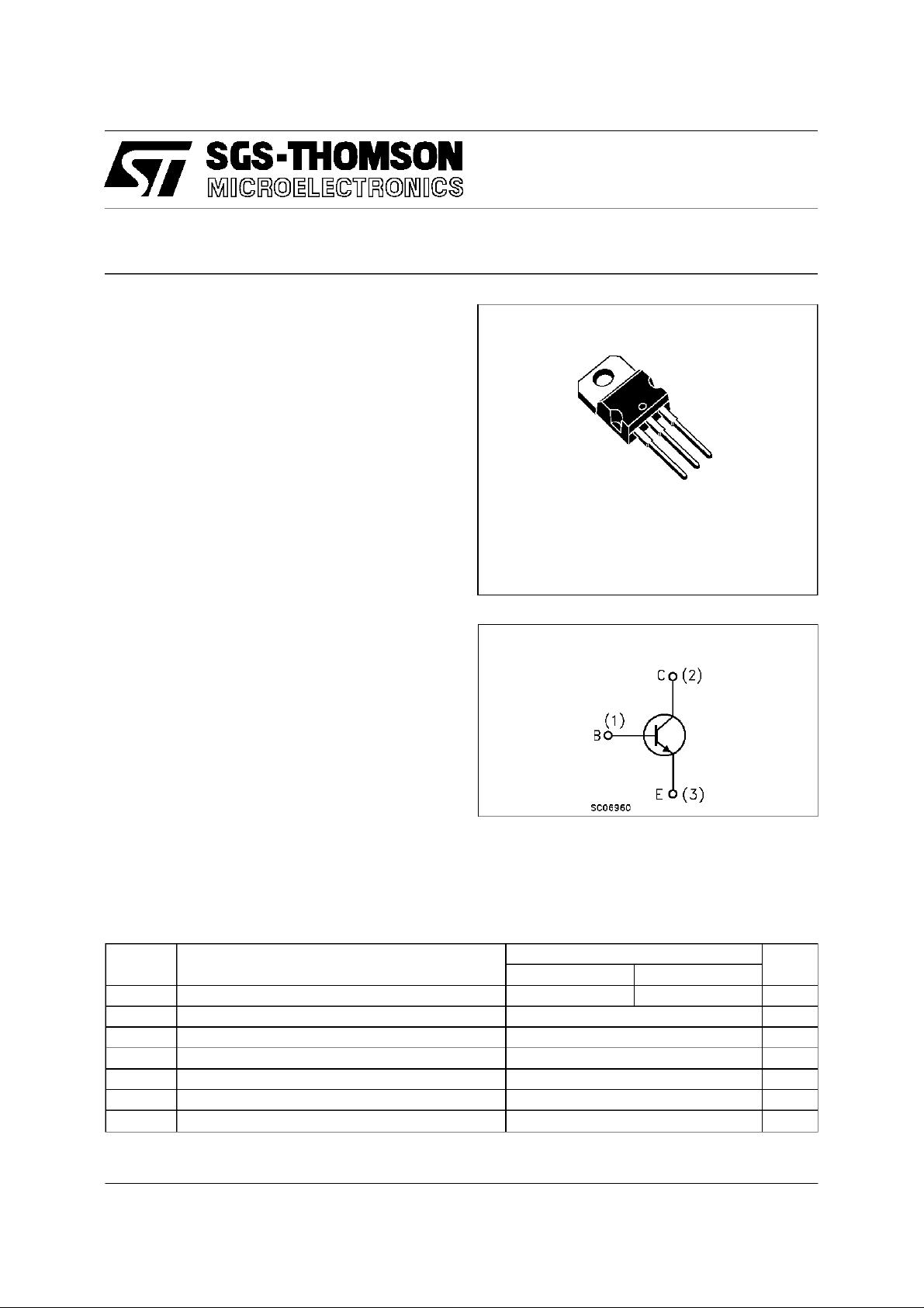
DESCRIPTION
The D44H8, and D44H11 are silicon
multiepitaxial planar NPN transistors mounted in
Jedec TO-220 plastic package.
They are inteded for various switching and
general purpose applications.
D44H8, D44H11 are complementary with D45H8,
D45H11.
TO-220
D44H8
D44H11
3
2
1
INTERNAL SCHEMATIC DIAGRAM
ABSOLUTE MAXIMUM RATINGS
Symb o l Parameter Val u e Uni t
D44H8 D44H1 1
V
V
I
P
T
Collector-Emitter Voltage ( IB=0) 60 80 V
CEO
Emitter-Base Voltage ( IC=0) 5 V
EBO
Collect or Current 10 A
I
C
Collect or Peak Curr ent 20 A
CM
Tot al Dissipation at Tc≤ 25oC50W
tot
Storage Temperature -65 to 150
stg
Max. O per ating Junc tion Temperat u re 150
T
j
o
C
o
C
June 1997
1/5
D44H8/D44H11
THERMAL DATA
R
thj-case
Ther mal Resistance Junction-case Max 2.5
o
C/W
ELECTRICAL CHARACTERISTICS (T
=25oC unlessotherwise specified)
case
Symbol Parameter Test Condition s Min. Typ. Ma x. Unit
I
CBO
I
EBO
V
CEO(sus )
V
CE(sat)
Collector Cut- of f
Current (I
E
=0)
Emit ter Cut-o f f C urr ent
=0)
(I
C
∗ Collector-E mitter
Sust aining V olt ag e
∗ Collector-E mitter
V
=ratedV
CB
V
=5V 100 µA
EB
CEO
10 µA
IC=100mA
for D44H8
for D44H11
60
80
IC=8A IB=0.4A 1 V
Saturation Voltage
V
BE(sat )
∗ Base-Emitt er
IC=8A IB= 0.8 A 1.5 V
Saturation Voltage
∗ DC Current Gain IC=2A VCE=1V
h
FE
∗
Pulsed: Pulse duration = 300 µs, duty cycle≤ 2%
=4A VCE=1V
I
C
60
40
V
V
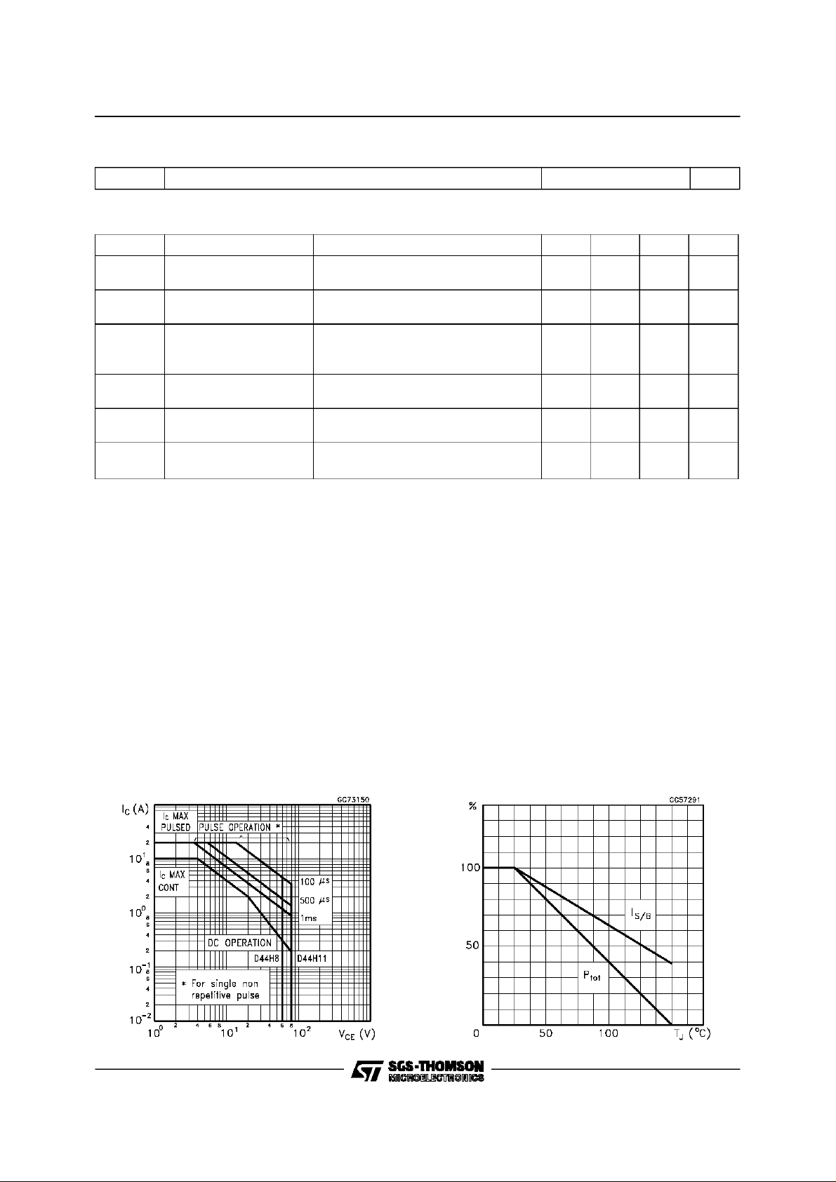
Safe Operating Area DeratingCurves
2/5

D44H8/D44H11
DCCurrent Gain
Collector-EmitterSaturation Voltage
DC Current Gain
Base-EmitterSaturationVoltage
3/5

D44H8/D44H11
TO-220 MECHANICAL DATA
DIM.
MIN. TYP. MAX. MIN. TYP. MAX.
A 4.40 4.60 0.173 0.181
C 1.23 1.32 0.048 0.051
D 2.40 2.72 0.094 0.107
D1 1.27 0.050
E 0.49 0.70 0.019 0.027
F 0.61 0.88 0.024 0.034
F1 1.14 1.70 0.044 0.067
F2 1.14 1.70 0.044 0.067
G 4.95 5.15 0.194 0.203
G1 2.4 2.7 0.094 0.106
H2 10.0 10.40 0.393 0.409
L2 16.4 0.645
L4 13.0 14.0 0.511 0.551
L5 2.65 2.95 0.104 0.116
L6 15.25 15.75 0.600 0.620
L7 6.2 6.6 0.244 0.260
L9 3.5 3.93 0.137 0.154
DIA. 3.75 3.85 0.147 0.151
mm inch
E
A
L4
D
F2
F1
G1
H2
G
F
C
D1
L2
Dia.
L5
L7
L6
L9
P011C
4/5

D44H8/D44H11
Informationfurnished is believed to be accurate and reliable.However, SGS-THOMSONMicroelectronics assumesno responsabilityfor the
consequencesof use of such informationnor for any infringementof patents orother rights ofthirdparties whichmay results fromits use.No
license isgranted byimplication orotherwiseunder anypatentor patentrights of SGS-THOMSONMicroelectronics. Specificationsmentioned
in this publicationare subject tochange without notice. This publicationsupersedes and replacesall informationpreviously supplied.
SGS-THOMSON Microelectronicsproducts arenotauthorizedfor useas criticalcomponentsin lifesupportdevices orsystems withoutexpress
written approvalof SGS-THOMSONMicroelectonics.
1997 SGS-THOMSON Microelectronics -Printed in Italy - All RightsReserved
Australia- Brazil - Canada- China- France - Germany- Hong Kong -Italy - Japan- Korea- Malaysia -Malta - Morocco - The Netherlands-
Singapore - Spain- Sweden - Switzerland- Taiwan- Thailand- UnitedKingdom- U.S.A
SGS-THOMSON MicroelectronicsGROUP OF COMPANIES
...
5/5
 Loading...