

SGS Thomson Microelectronics BYV54V-200, BYV541V-200 Datasheet
BYV54V
BYV541V
HIGH EFFICIENCY FAST RECOVERY RECTIFIER DIODES
FEATURES
n SUITED FOR SMPS
n VERY LOWFORWARD LOSSES
n NEGLIGIBLE SWITCHING LOSSES
n HIGH SURGE CURRENT CAPABILITY
n HIGH AVALANCHE ENERGY CAPABILITY
n INSULATED :
Insulating voltage = 2500 V
RMS
Capacitance = 45 pF
DESCRIPTION
Dual rectifier suited for switchmode power supply
and high frequency DC to DC converters.
Packaged in ISOTOPTMthis device is intended for
use in low voltage, high frequency inverters, free
wheeling and polarity protection applications.
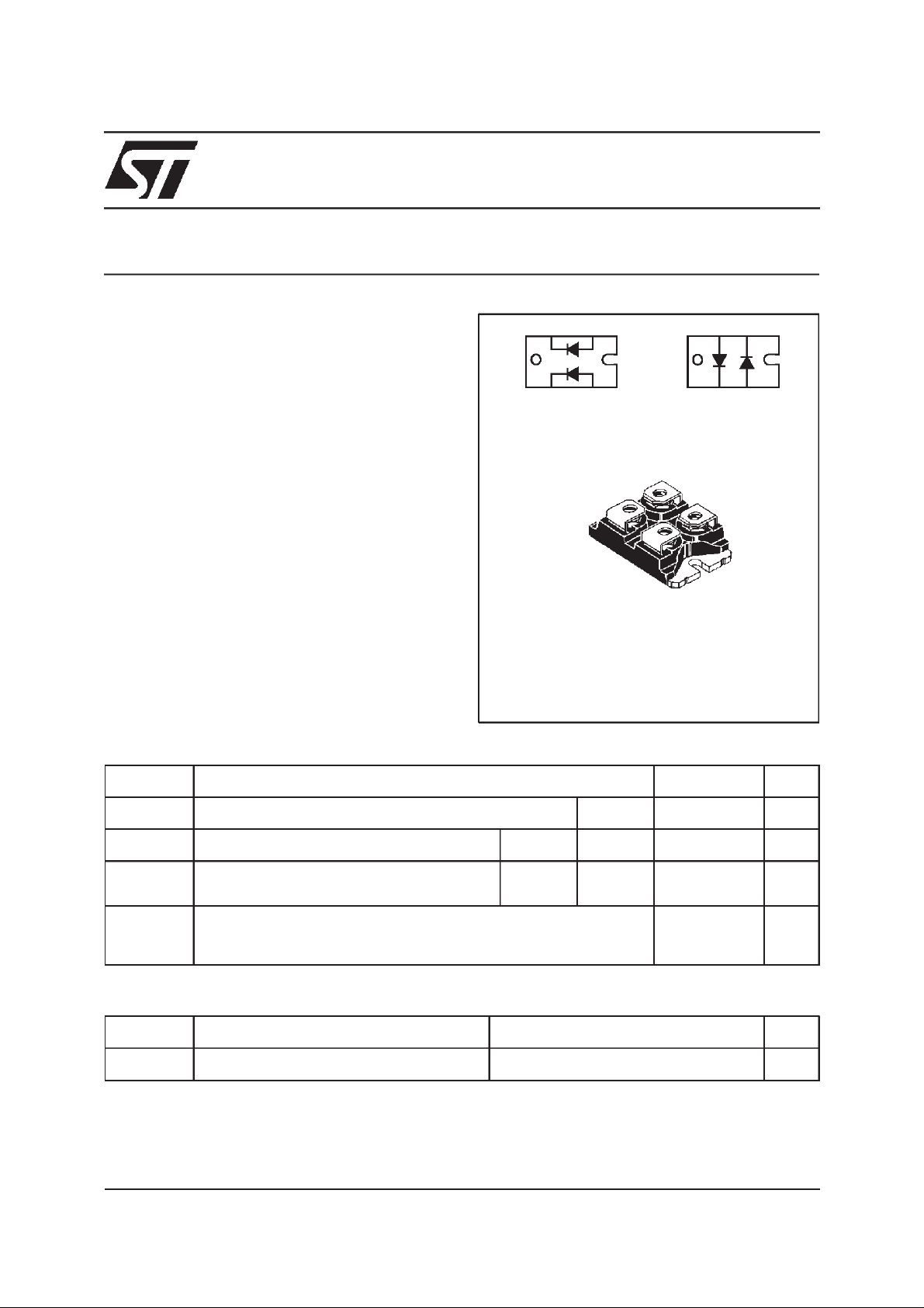
K2 A2
A1K1
BYV541V-200
ISOTOP
(Plastic)
A2 K1
BYV54V-200
A1K2
ABSOLUTE MAXIMUM RATINGS
Symbol Parameter Value Unit
I
F(RMS)
I
F(AV)
I
FSM
RMS forward current
Average forward current δ = 0.5
Surge non repetitive forward current
Per diode
Tc=90°C Per diode
tp=10ms
Per diode
100 A
50 A
1000 A
sinusoidal
Tstg
Tj
Storage and junction temperature range
-40to+
150
- 40 to+ 150
Symbol Parameter BYV54V / BYV541V Unit
V
RRM
Repetitive peak reverse voltage
200 V
ISOTOP is a trademark of STMicroelectronics.
May 2000 - Ed : 2E
°C
°C
1/5

BYV54V / BYV541V
THERMAL RESISTANCE
Symbol Parameter Value Unit
Rth (j-c)
Rth (c)
Junction to case
Coupling
Per diode
Total
1.2 °C/W
0.85
0.1 °C/W
When the diodes 1 and 2 are used simultaneously :
Tj-Tc (diode 1) = P(diode 1) x Rth(j-c)(Per diode) + P(diode 2) x Rth(c)
ELECTRICAL CHARACTERISTICS (Per diode)
STATIC CHARACTERISTICS
Symbol Test Conditions Min. Typ. Max. Unit
IR*
V
F**
Tj=25°CV
=V
R
RRM
Tj= 100°C
Tj= 125°CI
Tj= 125°CI
=50A
F
= 100 A
F
50 µA
5mA
0.85 V
1.00
Tj=25°CI
Pulse test :
* tp = 5 ms, duty cycle < 2%
** tp = 380 µs, duty cycle< 2 %
= 100 A
F
1.15
RECOVERY CHARACTERISTICS
Symbol Test Conditions Min. Typ. Max. Unit
trr Tj=25°CI
= 0.5A
F
Irr = 0.25A 40 ns
IR=1A
IF=1A
dIF/dt = -50A/µs60
VR= 30V
tfr Tj=25°CI
V
FP
Tj=25°CI
=1A
F
VFR= 1.1 x V
= 1A tr = 5ns 1.5 V
F
tr = 5ns 10 ns
F
2/5
 Loading...