

SGS Thomson Microelectronics BYT11-800, BYT11-600, BYT11-1000 Datasheet
SOFT RECOVERY
VERY HIGH VOLT AGE
SMALL RECOVERY CHARGE
BYT 11-600 →1000
FAST RECOVERY RECTIFIER DIODES
APPLICATIONS
ANTISATURATION DIODES FOR TRANSIS-
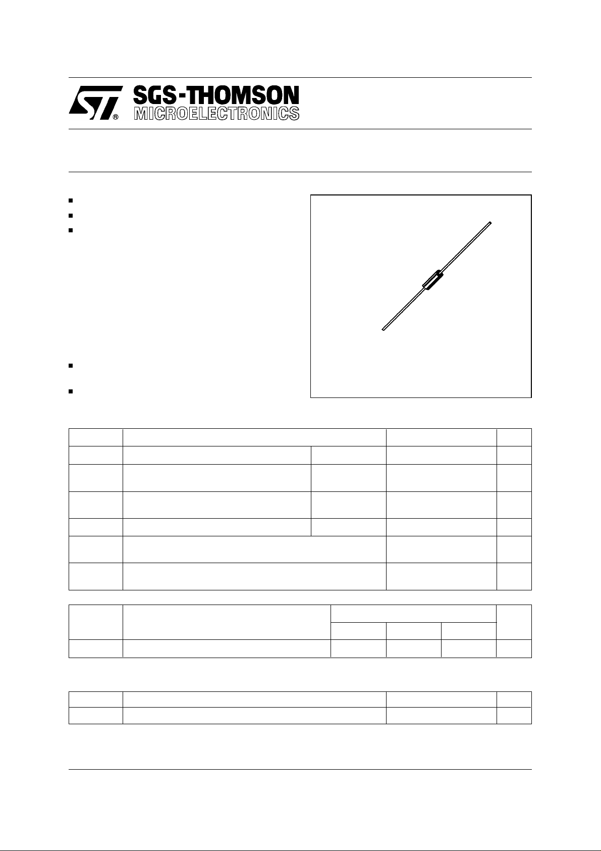
F 126
(Plastic)
TOR BASE DRIVE
SNUBBER DIODES
ABSOL UT E RATINGS (limiting values)
Symbol Parameter Value Unit
I
FRM
I
F (AV)
I
FSM
P
tot
T
stg
T
T
L
Symbol Parameter
Repetive Peak Forward Current
Average Forward Current * T
Surge non Repetitive Forward Current tp = 10ms
Power Dissipation *
Storage and Junction Temperature Range - 55 to + 150
j
Maximum Lead Temperature for Soldering during 10s at 4mm
from Case
≤ 20µs
t
p
75°C
a =
δ = 0.5
Sinusoidal
55°C
T
a =
BYT 11-
600 800 1000
20 A
1A
35 A
1.25 W
- 55 to + 150
230
°C
°C
Unit
V
RRM
Repetitive Peak Reverse Voltage 600 800 1000 V
THERMAL RESISTANCE
Symbol Parameter Value Unit
R
th (j - a)
* On infinite heatsink with 10mm lead length.
November 1994
Junction-ambient* 60
°C/W
1/4
BYT11-600 → 1000
ELECTRICAL CHARACTERISTICS
STATIC CHARACTERISTICS
Synbol Test Conditions Min. Typ. Max. Unit
I
R
V
F
Tj = 25°C
Tj = 25°C
V
= V
R
RRM
I
= 1A 1.3 V
F
20
RECOVERY CHARACTERISTICS
Symbol Test Conditions Min. Typ. Max. Unit
t
rr
Tj = 25°C IF = 0.5A IR = 1A I
= 0.25A
rr
100 ns
To evaluate the conduction losses use the following equations:
V
= 1.1 + 0.075 IF P = 1.1 x I
F
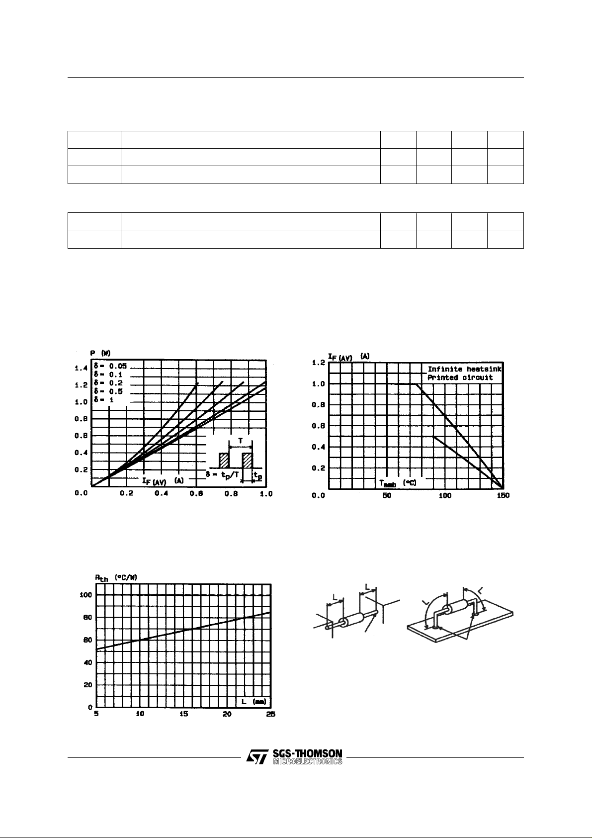
Figure 1. Maximum average power
dissipation versus average forward curr ent .
F(AV)
+ 0.075 I
F2(RMS)
Figure 2. Average forward current versus
ambient temperature.
µA
Figure 3. Thermal resistance versus lead
length.
2/4
Moun ting n°1
INFINIT E HE ATSIN K
Test point of
t
lead
Moun ting n°2
PRINTED CIRCUIT
Soldering
 Loading...