

Page 1
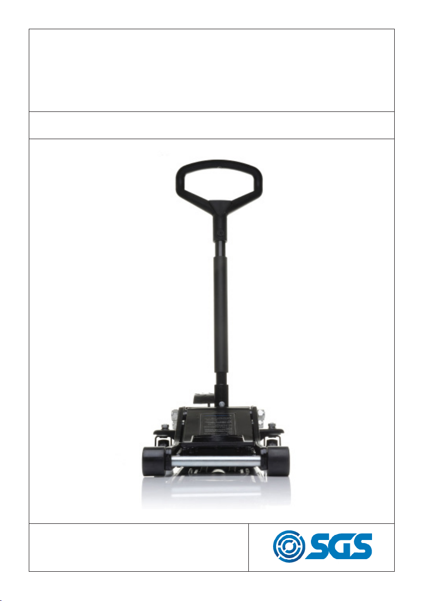
TJ2PRO LOW PROFILE
TROLLEY JACK
OWNER’S MANUAL
FOR YOUR SAFETY
PLEASE READ THESE INSTRUCTIONS CAREFULLY
AND RETAIN THEM FOR FUTURE USE.
Page 2
SPECIFICATION
MAXIMUM CAPACITY 2000KG
RETRACTED HEIGHT 70MM
MAXIMUM HEIGHT 500MM
WARNING
• Read and understand all warnings and instructions prior to use.
• Do not overload this jack beyond its rated capacity.
• This jack is a lifting device only.
• This jack is designed for use on hard level surfaces only.
• The load must be supported by jack stands once raised.
• Do not dolly or move the vehicle while it is on the jack.
• Lift only on areas as specified by the vehicle manufacturer.
• Only attachments and/or adaptors supplied by sgs shall be used.
• No alterations to the jack shall be made.
• Failure to heed these warnings may result in damage to the jack
and/or failure resulting in personal injury or property damage.
• Inspect the jack before each use.
INSPECTION BEFORE EACH USE
Before each use a visual inspection shall be made for abnormal
conditions such as cracked welds, damaged, bent, worn, loose or
missing parts.
This jack should be inspected immediately if it is believed to have been
subjected to an abnormal load or shock. Owner/operators should be
aware that repair of this jack requires specialised equipment and
knowledge.
WWW.SGS-ENGINEERING.COM
PAGE 2
Page 3

RAISING A VEHICLE
1. Make sure the jack and vehicle are on a hard level surface.
2. Always set the vehicle handbrake and chock the wheels.
3. Consult the vehicle owner’s manual to ascertain the location of
jacking points and position the jack beneath the lift point.
4. Turn the handle counter clockwise to the closed position.
5. To raise the vehicle pump the handle up and down. Do not over
extend the jack past the maximum height.
6. Place jack stands beneath the vehicle at locations recommended
by the vehicle manufacturer. Do not work under the vehicle
without the use of jack stands. Jacks are not designed to maintain
heavy loads for long periods of time. Do not attempt to place jack
stands simultaneously under both ends of a vehicle or along one
side of a vehicle.
7. Turn the handle slowly clockwise to lower the vehicle onto the jack
stands.
LOWERING A VEHICLE
1. Turn the handle counter clockwise to close the release valve.
2. Pump the handle to lift the vehicle off the jack stands.
3. Remove the jack stands. Do not get under the vehicle while the
vehicle is being lowered.
4. Turn the handle slowly clockwise to lower the vehicle onto the
ground.
PAGE 3
Page 4

MAINTENANCE GUIDE
Daily. See INSPECTION BEFORE EACH USE (page 2).
Monthly. Lubrication is critical to jacks as they support heavy
loads. Any restriction due to dirt, rust or corrosion can cause
either slow movement or rapid jerks damaging the internal
components. The following steps are designed to keep the
jack maintained and operational:
1. Open the release valve by turning the handle knob counter
clockwise and push the ram to its lowest position
2. Remove the filler plug.
3. Fill with clean hydraulic jack oil. Do not use hydraulic brake
fluid.
4. Reinstall the filler plug.
Add lubrication to all moving parts as needed.
Every 6 months. Carry out a thorough inspection for serviceability of component parts Visually inspect for oil leaks (only
a slight oil seepage is permissible). If a leak is found, take the
jack out of service and consult with SGS Engineering.
Annually. Check the ram oil level as follows:
1. Ensure the ram is fully retracted by turning the knob fully
anticlockwise.
2. Remove the cover plate, located at the base of the handle
housing, to gain access the ram, then remove the ram filler
plug.
3. Lift the jack so that it is vertical, resting on its front wheels
and check the oil level. It should be level with the bottom
of the oil filler hole. If necessary, top up with Hydraulic oil.
4. Replace filler plug and purge system of air (see page 5).
WWW.SGS-ENGINEERING.COM
PAGE 4
Page 5

CHECK THE OIL LEVEL
1. Turn the handle clockwise to allow the ram to fully retract. It may
be necessary to apply force to the saddle to lower the ram.
2. Remove the inspection plate.
3. With the jack in the level position remove the oil fill plug. The oil
should be level with the bottom of the fill hole. If not, top up but
do not overfill. Always fill with new, clean hydraulic jack oil.
4. Replace fill plug and inspection plate.
5. Check jack operation.
6. Purge air from the system as required.
SYSTEM AIR PURGE
1. Fully lower the saddle.
2. Turn the handle clockwise one full turn to open.
3. Locate and remove the oil filler plug.
4. Pump the handle eight full strokes to release pressurised air which
may be trapped in the reservoir.
5. Re-install oil filler plug
6. Turn handle counter clockwise one full turn.
FACTORY SERVICE
If this hydraulic jack if found to be damaged in any way, worn or
operating abnormally it should be removed from service until
inspected by an authorised repair centre.
Owner/operators should be aware that the repair of this jack requires
specialised equipment and knowledge. Only factory authorised parts,
labels and decals shall be used on this equipment. An annual
inspection of this jack by an authorised repair centre is recommended
to ensure the jack maintains an optimum operating condition.
PAGE 5
Page 6

TROUBLESHOOTING
PROBLEM POSSIBLE CAUSE ACTION
JACK WILL NOT LIFT TO FULL
HEIGHT
JACK WILL NOT HOLD LOAD RELEASE VALVE NOT CLOSING
LOW OIL LEVEL CHECK OIL LEVEL AND REFILL IF
OIL CONTAMINATED
PUMP VALVES NOT SEALING
CYLINDER RAM BINDING
NECESSARY
CONTACT CUSTOMER SERVICE
LIFT ARM WILL NOT LOWER CYLINDER RAM BINDING
JACK FEELS SPONGY WHEN
LIFTING
PARTS WORN
INTERNAL DAMAGE
BROKEN RETURN SPRING
LIFT ARM LINKAGE BENT OR
BINDING
SEE AIR PURGE SECTION PURGE TRAPPED AIR
REPLACEMENT PARTS LIST
ITEM DESCRIPTION QTY
1 SADDLE COVER 1
2 SADDLE 1
3 LIFTING ARM 1
4 UPPER HANDLE 1
5 COTTER PIN 4X50 1
6 CONNECTING BLOCK 1
7 WASHER 2
8 RETURN SPRING 2
9 NUT 18 2
10 SPRING PAD 18 2
11 FLAT PAD 18 2
12 WHEEL FORK SLEEVE 2
13 FRONT WHEEL FORK 2
14 FRONT WHEEL PIN 1
15 SUPPORT SHAFT 1
16 RIGHT PLATE 1
17 LEFT PLATE 1
18 WASHER 20 2
19 NUT 20 2
20 WASHER 14 2
21 NUT 14 2
22 DISK TOOLS 1
23 SCREW 8X16 2
CONTACT CUSTOMER SERVICE
ITEM DESCRIPTION QTY
24 SPRING PAD 8 2
25 SHAFT PIN 1
26 POWER UNIT 1
27 SPRING PAD 12 4
28 SCREW 12X25 2
29 BOLT 6X20 1
30 PAD 10 1
31 PUSHING PLATE 1
32 VALVE 1
33 FLAT PAD 6 1
34 SPRING PAD 6 1
35 NUT 6 1
36 SHAFT PIN 2
37 NUT 12 2
38 FLAT PAD 12 2
39 BUTTERFLY NUT 8 1
40 FLAT PAD 16 2
41 NUT 16 2
42 HANDLE SOCKET PIN 1
43 BACK WHEEL 2
44 SHAFT 1
45 HANDLE SOCKET PIN 1
WWW.SGS-ENGINEERING.COM
PAGE 6
Page 7

REPLACEMENT PARTS DIAGRAM
PAGE 7
Page 8

WARRANTY
This SGS product is covered by a 24 month warranty from the
initial date of purchase. This is a domestic warranty provided
directly by SGS Engineering. Please keep a recipt of your
pucrchase as this may be required as proof of purchase.
You will invalidate your warranty if the product is found to
have been misused, tampered with, modified, overloaded
or used for an application for which it was not designed. The
warranty will also be rendered invalid if the maintenance
prodcedure has not been followed.
You must contact SGS Engineering prior to returning any
product. This warranty does not effect your statutory rights.
CE MARK
SGS ENGINEERING IS COMMITTED TO DESIGNING, MANUFACTURING,
AND MARKETING PRODUCTS THAT MEET OR EXCEED THE NEEDS OF
THE CUSTOMERS WE SERVE. SGS ENGINEERING CAN SUPPLY A LETTER
OF INCORPORATION OR A DECLARATION OF CONFORMITY AND CE
MARKING FOR PRODUCTS THAT CONFORM WITH EUROPEAN COM-
MUNITY DIRECTIVES.
FOR MORE PRODUCTS PLEASE BROWSE OUR WEBSITE: WWW.SGS-ENGINEERING.COM
• GAS STRUTS FOR CARS, DOMESTIC & INDUSTRIAL APPLICATIONS
• HYDRAULIC BOTTLE JACKS, TROLLEY JACKS, AXLE STANDS, FARM JACKS
• WORKSHOP AND INDUSTRIAL HYDRAULIC PRESSES
• HYDRAULIC CYLINDERS, PUMPS, TOOLS & EQUIPMENT
FOR YOUR SAFETY
PLEASE READ THESE INSTRUCTIONS CAREFULLY
AND RETAIN THEM FOR FUTURE USE.
Page 9

SGS Engineering (UK) Ltd
West Side Park
Derby, DE21 7AZ
EC Declaration of Conformity
This is an important document and should be retained
Raynesway
MANUFACTURER’S NAME:
TYPE OF EQUIPMENT:
PART NUMBER:
APPLICATION OF EC COUNCIL DIRECTIVES / STANDARD:
2006/42/EC Machinery Directive as amended by directive
2009/127/EC
EN1494:2000 + A1:2008 Mobile or movable jacks and associated lifting
equipment
The Supply of Machinery (Safety) Regulations 2008 Statutory instrument 2008
No.1597
The Supply of Machinery (Safety) (Amendment) Regulations 2011 Statutory
instrument 2011 No.2157
SGS Engineering (UK) Ltd
Hydraulic Trolley Jack
TJ2PRO
I, the undersigned, hereby declare that the equipment specied above conforms to the above European Communities Directive(s) and Standard(s).
PLACE:
DATE:
Derby, UK
24th JUNE 2017
(Signature)
Robert Wyatt
Company Secretary
 Loading...