

SGS SSB100 Owner's Manual
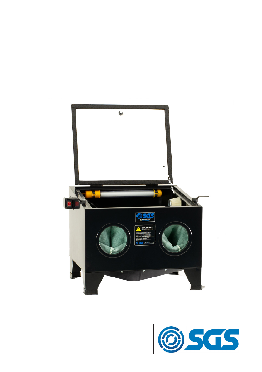
SSB100
SHOT BLAST CABINET
OWNER’S MANUAL
FOR YOUR SAFETY
PLEASE READ THESE INSTRUCTIONS CAREFULLY
AND RETAIN THEM FOR FUTURE USE.
SPECIFICATION
TOOL MODEL SSB100
TYPE BENCH MOUNTED
VOLTS 12V
MIN AIR REQUIREMENT 10 CFM
MIN AIR REQUIREMENT 80-100 PSI
WARNING
Read and understand instructions before use.
Always wear eye/face and hand protection.
Do not use any silica based abrasives with this cabinet.
Silica based abrasives have been linked to severe res-
piratory disease. Always use recommended abrasives.
Abrasives used in this unit may be covered by COSHH.
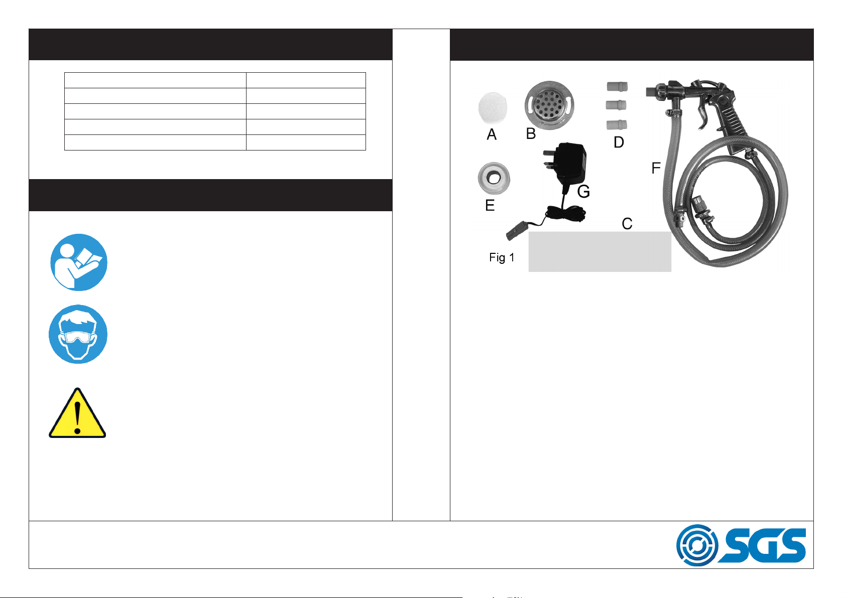
INVENTORY
A - Foam Vent Filter
B - Air Vent Cover
C - Spare protective film
D - Ceramic Nozzles 4, 5, 6 & 7mm (one nozzle is fitted)
E - PTFE tape
F - Gun c/w air and pickup hoses
G - 12V transformer & cable
WWW.SGS-ENGINEERING.COM
PAGE 2
PAGE 3
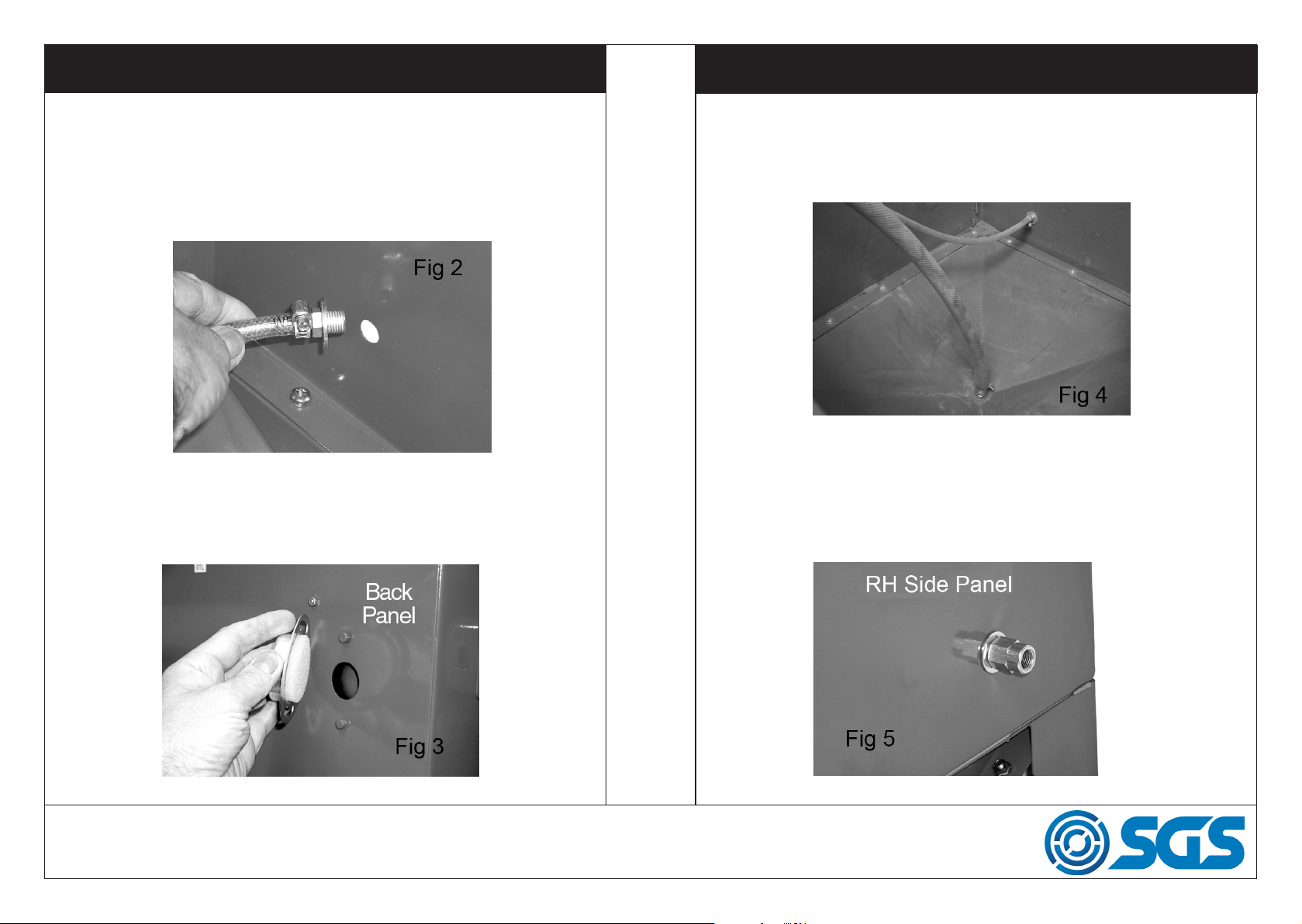
ASSEMBLY
ASSEMBLY
The unit is shipped fully assembled, except for the air vent filter and the
gun with attached hoses. First, remove the grid and all the various loose
components from within the cabinet.
The end of the air inlet hose, connected to the gun, is inserted through
the 16mm dia. hole in the cabinet from the inside, as shown in Fig 2. Ensure a flat washer is threaded on to the adapter as shown.
Thread a flat washer, followed by the extended nut, onto the adapter,
from the outside of the cabinet, and tighten. Insert the circular foam filter
into the recess in the Air Vent Cover, and attach the cover to the rear of
the cabinet as shown in Fig 3, having first prised out the plastic bung from
the vent hole.
The pick up hose should be attached to the bottom of the cabinet as
shown in Fig 4, using the large washer and nut underneath.
Replace the grid, ensuring the feet face downwards with the cut away
section at the rear of the cabinet.
Finally, connect the air supply to the extended nut shown in Fig 5. Use of
the PTFE tape supplied with ensure an airtight seal.
• The air supply should be dry and capable of delivering a minimum
of 10 cu ft/min at 100 lbf/in.
WWW.SGS-ENGINEERING.COM
PAGE 4
PAGE 5
 Loading...