

SGS SCT501 Owner's Manual

FOR YOUR SAFETY
PLEASE READ THESE INSTRUCTIONS CAREFULLY
AND RETAIN THEM FOR FUTURE USE.
OWNER’S MANUAL
5 IN 1 MULTI- TOOL
PAGE 2
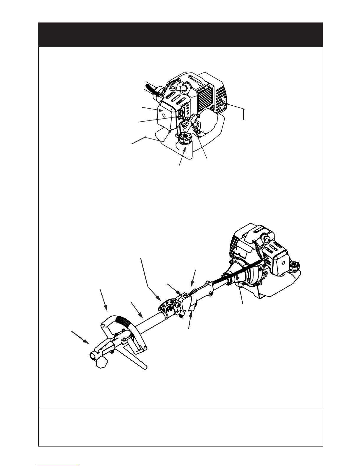
PARTS LOCATION
Air
filter
cover
Choke
lever
Primer
bulb
Fuel tank
Pull start
Muffler
Throttle
cable
Throttle
control
Throttle
trigger
On/off
switch
Harness
suspension
point
Main
shaft
tube
Loop
handle
Split shaft
connector
WWW.SGS-ENGINEERING.COM
CALL FOR ASSISTANCE: 01332 576 850
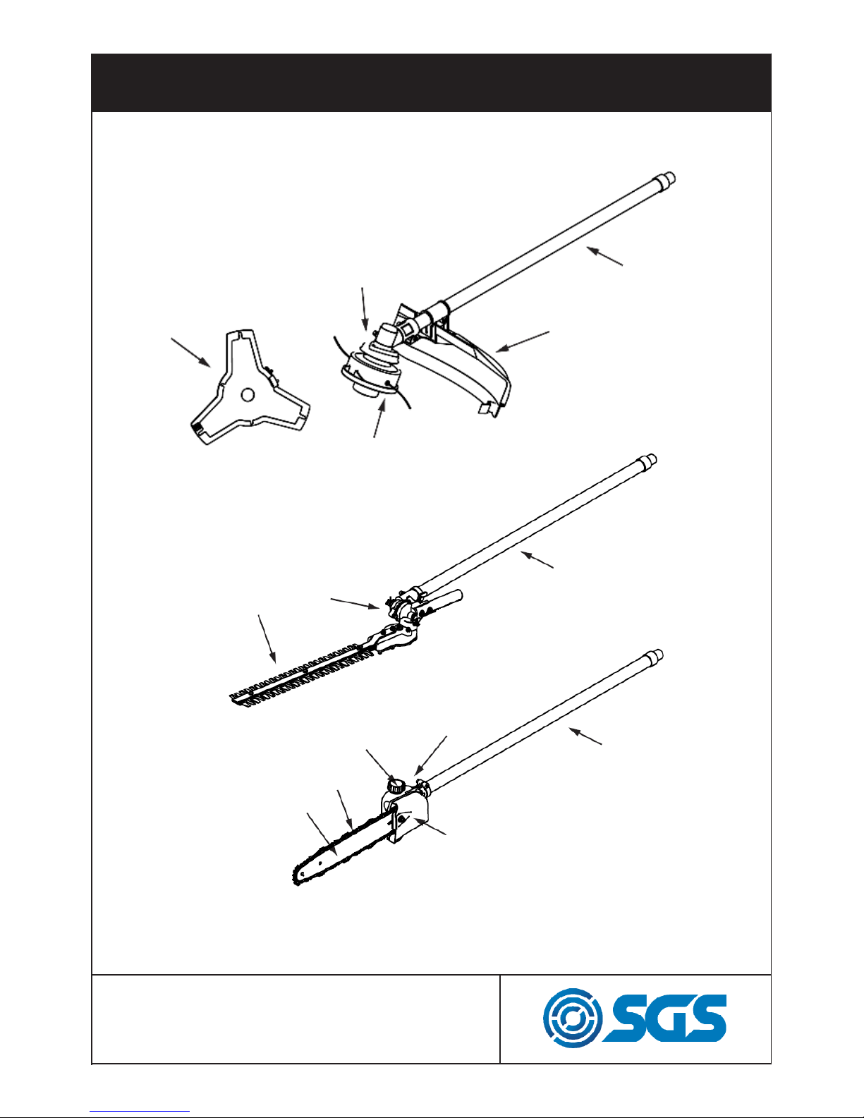
PAGE 3
Attachment
guard
Brush
cutter gear
case
Nylon
trimmer
Three point
blade
Working
shaft tube
PARTS LOCATION
Working
shaft tube
Working
shaft tube
Hedge
trimmer
gear case
Hedge trimmer
attachment
Pruner guide bar
Pruner saw
Chain cover
Pruner
gear case
Oil tank

PAGE 4
FOR SAFE OPERATION
Read operator’s instruction book before
operating this machine.
Read, understand and follow all warnings.
Wear head, eye and ear protection.
Use suitable work-wear to protect yourself.
Watch out for thrown objects & ricochets
The operator of the machine must ensure,
while working, that no persons or animals
come closer than 50 feet (15 meters).
Only use non--metallic, flexible
cutting attachments, i.e. trimmer
heads with trimmer line.
WWW.SGS-ENGINEERING.COM
CALL FOR ASSISTANCE: 01332 576 850

PAGE 5
FOR SAFE OPERATION
GLOVES
Gloves should be worn when necessary, e.g., when
fitting cutting attachments.
HEARING PROTECTION
Wear hearing protection that provides adequate
noise reduction.
EYE PROTECTION
Always wear approved eye protection. If you use a
visor then you must also wear approved protective
goggles. Approved protective goggles must comply with your countries relevent safety standard.
BOOTS
Wear sturdy, non--slip boots.
CLOTHING
Wear clothes made of a strong fabric and
avoid loose clothing that can catch on twigs and
branches. Always wear heavy, long pants. Do not
wear jewellery, shorts sandals or go barefoot. Secure hair so it is above shoulder level.

PAGE 6
FOR SAFE OPERATION
The only accessories you can operate with this engine unit are the cutting attachments we recommend.
Never use wire, rope, string, etc.
Never use the machine if you are tired, if you have
drunk alcohol, or if you are taking medication that
could affect your vision, your judgment or your coordination.
Never use the machine in extreme weather conditions
such as severe cold, very hot and/or humid climates.
Never use a machine that has been modified in any
way from its original specification.
Wear personal protective equipment.
Never use a machine that is faulty. Carry out the
checks, maintenance and service instructions described in this manual. Some maintenance and service
measures must be carried out by trained and qualified
specialists.
The strimmer attachment is only designed for
trimming grass.

PAGE 7
FOR SAFE OPERATION
All covers and guards must be fitted before starting.
Make sure the spark plug cap and lead are not damaged. Otherwise you could get an electric shock.
The machine operator must ensure that no people
or animals come closer than 50 feet (15 meters) while
working. Stay clear of spinning line.
Secure or remove loose clothing or clothing with
loosely hanging ties, straps, tassels, etc. They can be
caught in moving parts.
Being fully covered also helps protect you from debris
and pieces of toxic plants thrown by spinning line.
Keep handles free of oil and fuel.
Always keep the engine on the right hand side of your
body. Hold the unit firmly with both hands.
Keep trimmer head below waist level.

PAGE 8
- Make sure the chain and sprocket are correctly adjusted
before operating the pruner. Never attempt chain
adjustment with the engine running!
• Always make sure the cutting attachment
is properly installed and firmly tightened before operation.
• Never use a cracked or warped guide bar: replace it
with a serviceable one and make sure it fits properly.
• If a saw blade should bind fast in a cut, shut off the
engine immediately. Push the branch or tree to ease the
bind and free the blade.
• Do not operate the pole pruner with the muffler removed.
• When cutting a limb that is under tension, be alert for springback
so that you will not be struck by the moving
limb.
• Always stop the engine immediately and check for damage if you
strike a foreign object or if the machine becomes tangled.
Do not operate with broken or damaged equipment.
• Do not make unauthorized modifications or substitutions to
the guide bar or chain.
• Never allow the engine to run at high RPM without a load.
Doing so could damage the engine.
• Keep the pruner as clean as possible.
FOR SAFE OPERATION
IMPORTANT
WWW.SGS-ENGINEERING.COM
CALL FOR ASSISTANCE: 01332 576 850

PAGE 9
A standard package contains the items as shown below.
SET UP
(1) Guide bar
(2) Saw chain
(3) Transmission
(4) Sprocket
(5) Chain tension adjust screw
(6) Nut
(7) Chain tensioner nut
(8) Chain cover
The saw chain has very sharp edges. Use protective
gloves for safety.
WARNING
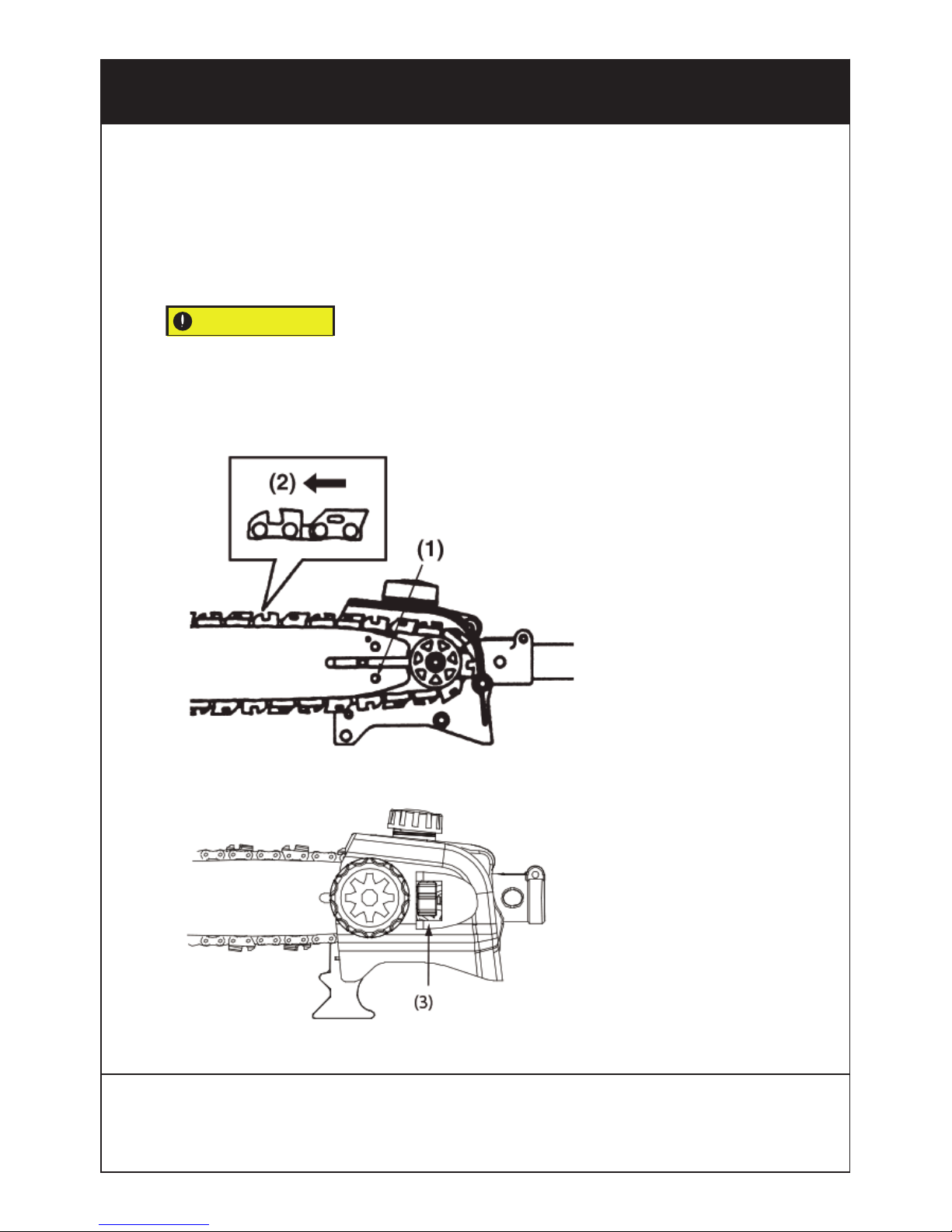
PAGE 10
1. Loosen the nut and remove the chain cover.
2. Mount the guide bar then fit the saw chain around the
bar and sprocket.
3. Fit the chain tensioner nut into the lower hole of the
guide bar, then install the chain cover, and fasten the
mounting nut to finger tightness.
Pay attention to the correct direction of
the saw chain.
SET UP
IMPORTANT
(1) Hole
(2) Moving direction
(3) Toolless chain tensioner roller
WWW.SGS-ENGINEERING.COM
CALL FOR ASSISTANCE: 01332 576 850
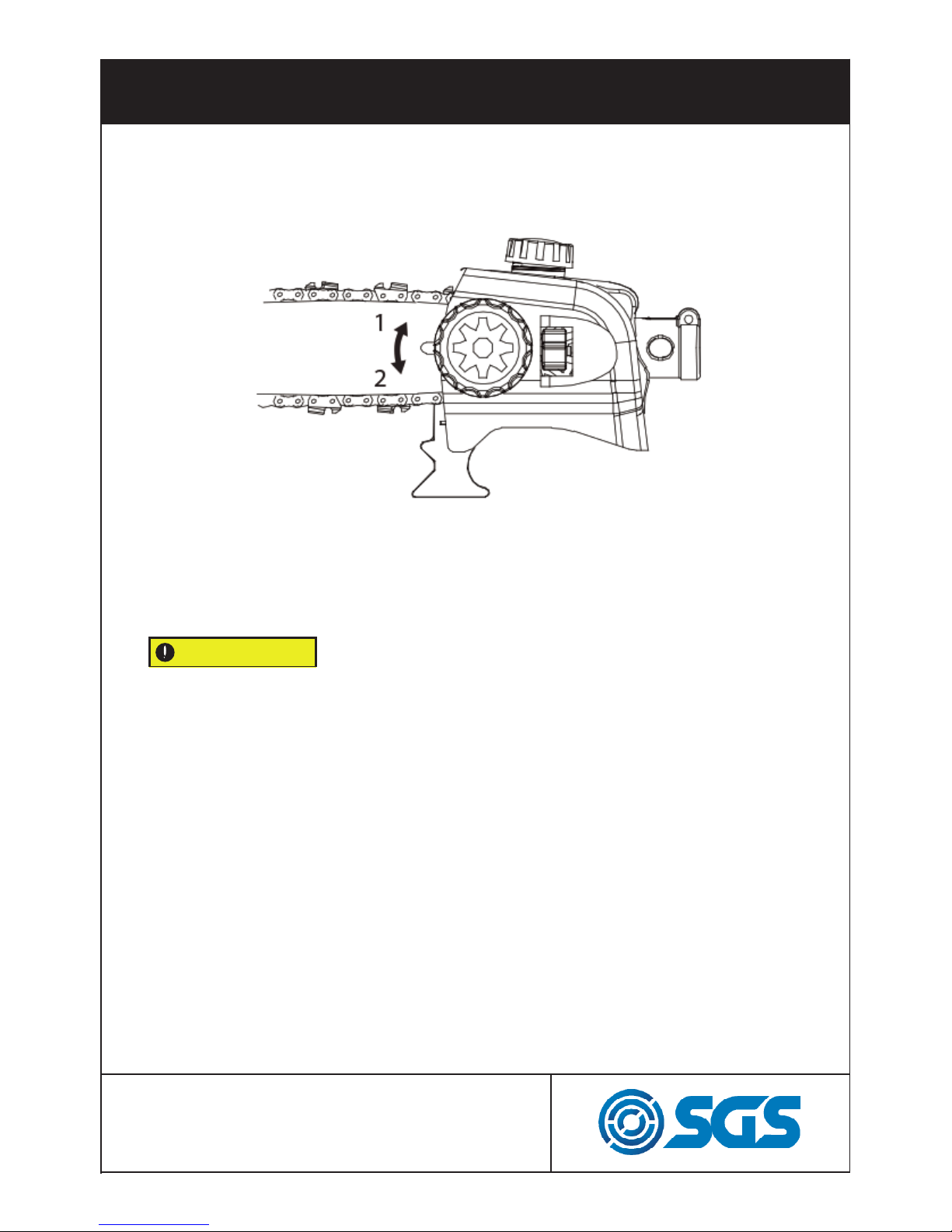
PAGE 11
4. Adjust the chain tension by turning the tensioner screw until
the tie straps just touch the bottom side of the bar rail.
SET UP
5. Tighten the mounting nut securely with the bar tip
held up (TORQUE: 8.9 ~ 11.7 N.m./90 ~ 120 kg-cm). Then
check the chain for smooth rotation and correct tension
while moving it by hand. If necessary, readjust.
Balance Unit
1. Put on harness strap and attach it to the unit suspension
point.
2. Depending on the working posture, insert hook up or down
the suspension point until the unit balances and the strap fits
your body.
It is very important to maintain the proper chain tension.
Rapid wear of the guide bar or the chain coming off easily
can be caused by improper tension.
IMPORTANT
(a) Loosen (b) Tighten
PAGE 12
SET UP
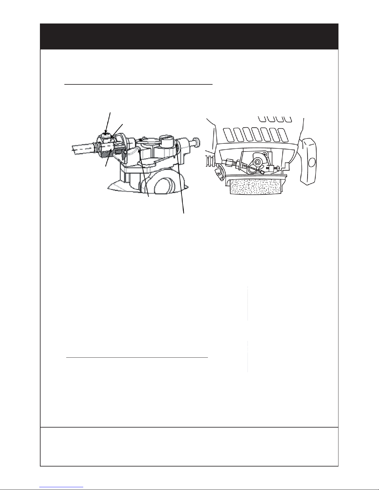
CONNECTING THROTTLE WIRE
M3 screw
Insert the
cable
to the end
of
adjuster
Full on
stopper
Idling adjust screw
1. Connect throttle wire with carburettor. Insert the cable
to the end of adjuster fix the throttle cable by tightening the
M3 screw. (Tightening torque: 0.4 ~ 0.8 N.m.)
2. Make sure the ‘STOPPER-PLATE’ of carburettor moves
to contact with ‘IDLING ADJUST SCREW’ and the ‘SWINGARM’ of carburettor moves to contact with ‘FULL ON STOPPER’ by gripping throttle lever.
CONNECTING SWITCH WIRES
Connect the switch wires between the engine and the main
unit. Pair wires of the same colour.
WWW.SGS-ENGINEERING.COM
CALL FOR ASSISTANCE: 01332 576 850
PAGE 13
SET UP
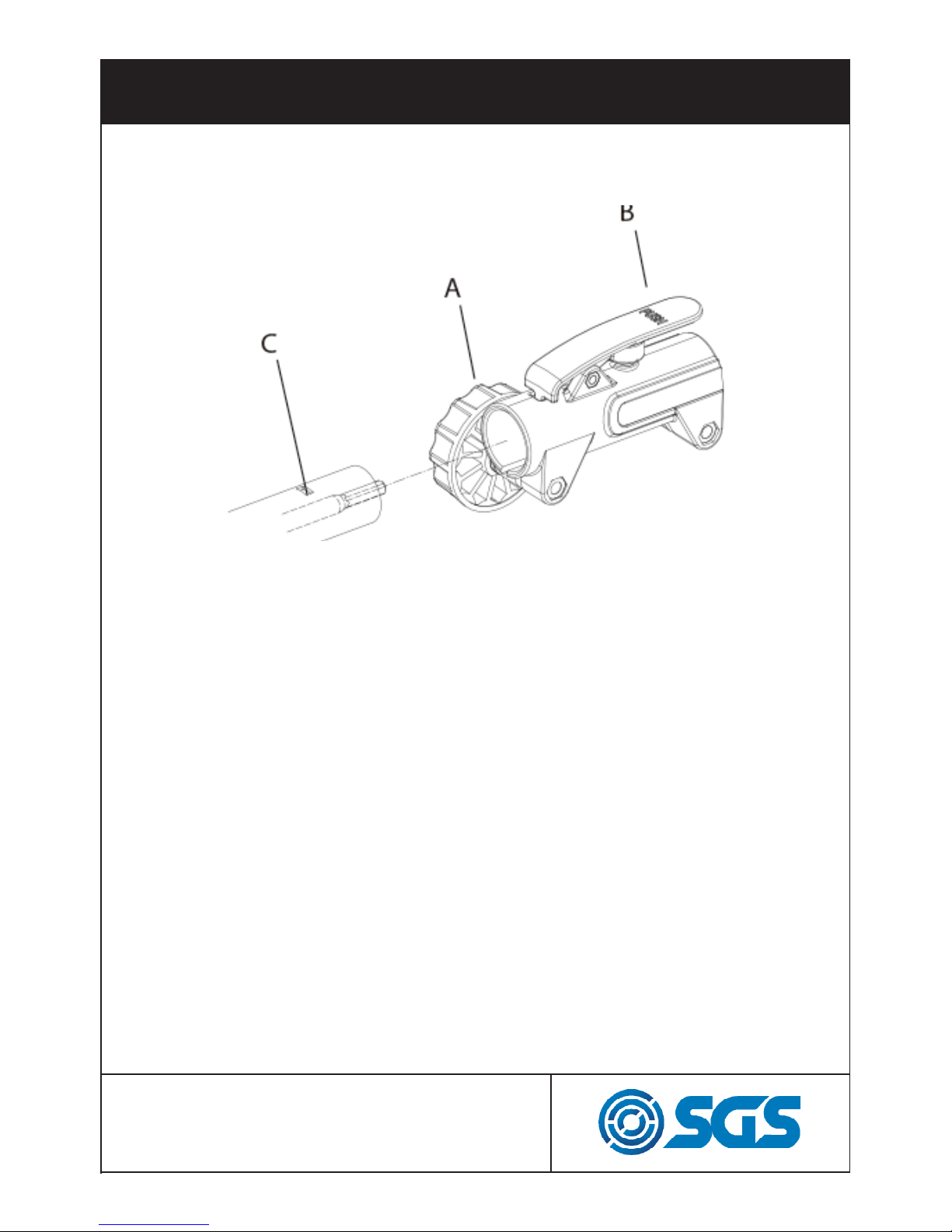
Connecting the shaft
To connect the working shaft to the main shaft with the
coupler:
1. Loosen the Locking Knob (A) counter clockwise so the
working shaft can be inserted into the tube coupler.
2. Press the Push Button (B) and gently rotate the working
shaft back and forth while inserting to make sure the drive
shaft is placed in position.
3. Release the Push Button to lock the hole (C) of the
working shaft tube. The Push Button is connected to a
spring-loaded detent that can snap the working tube in
position
4. Turn the Locking Knob clock-wise to secure the
connection.
PAGE 14
SET UP
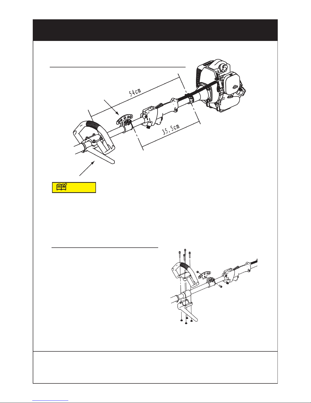
Loop
handle
Suspension
point
HANDLE AND SUSPENSION POINT
The recommended position of the handle and suspension
point is marked above. However you may adjust the position
to make sure it is comfortable for you.
INSTALLATION OF HANDLE
Set the upper part and lower part of
the handle at the right position.
Tighten the loop handle with the
screw and nut.
Insert the nuts (4) into the countersunk holes in the lower handle and
secure the top part of the
handle with the bolts supplied (4).
ZZ
NOTE
WWW.SGS-ENGINEERING.COM
CALL FOR ASSISTANCE: 01332 576 850
PAGE 15
SET UP
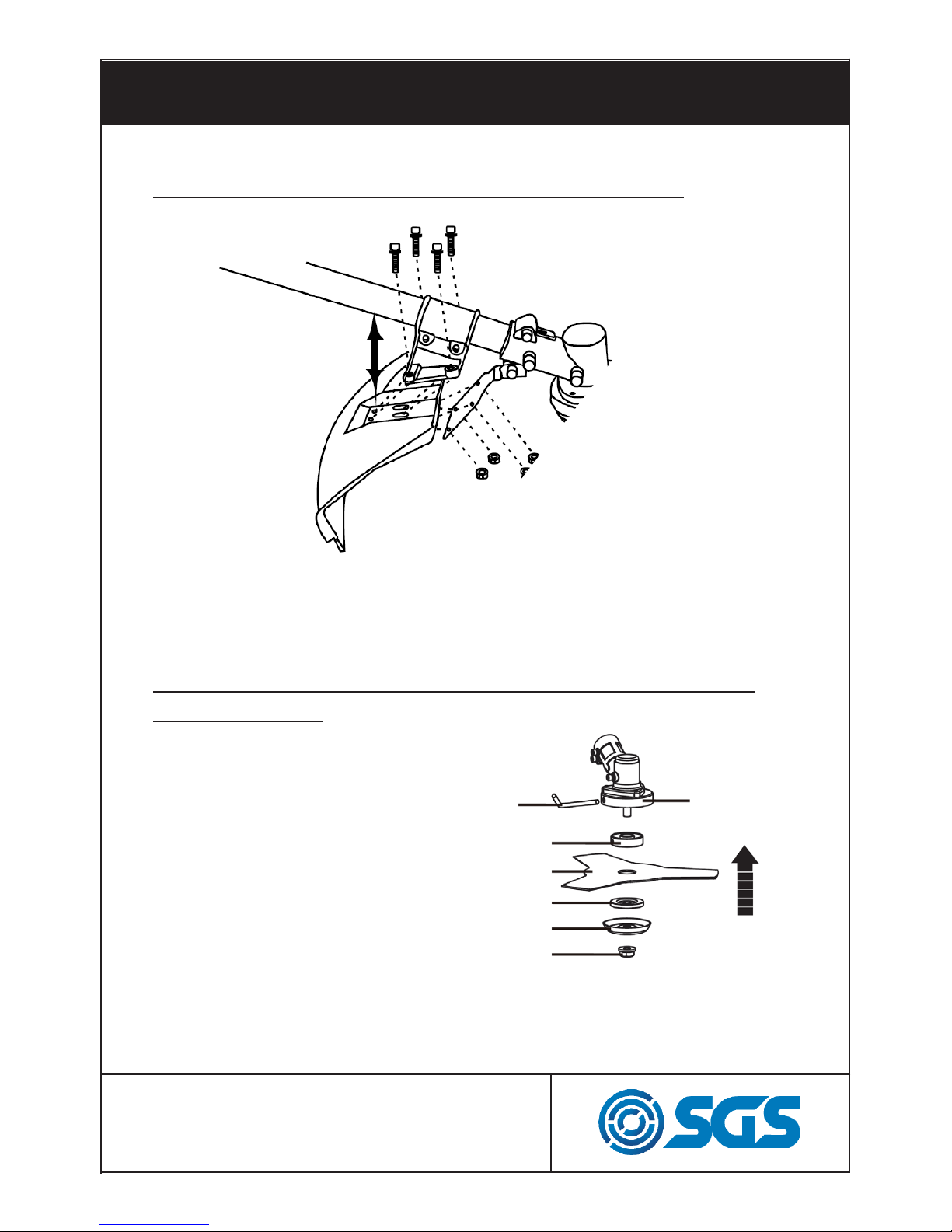
INSTALLING CUTTING ATTACHMENT GUARD
Put the cutting attachment guard on the gearbox,
attach it with the nuts and bolts provided.
BRUSH CUTTER AND EDGE TRIMMER INSTALLING
METAL BLADE
Key
Gear case
Collar ring
Metal blade
Washer
Washer
Nut
1- Insert the key wrench
into the gear case locking
hole.
2- Screw the collar ring on
the shaft thread.
3- Secure metal blade
between collar ring and
washer.
4- Place the washer.
5- Screw the nut.

PAGE 16
SET UP
INSTALLING THE NYLON LINE (NYLON CUTTER HEAD)
Gear case
Key
Collar ring
Nylon spool
1- Insert the key wrench into the gear case locking hole.
2- Screw the collar ring on the shaft thread.
3- Screw the nylon spool on the shaft thread.
4- Check the spool is secured tightly.
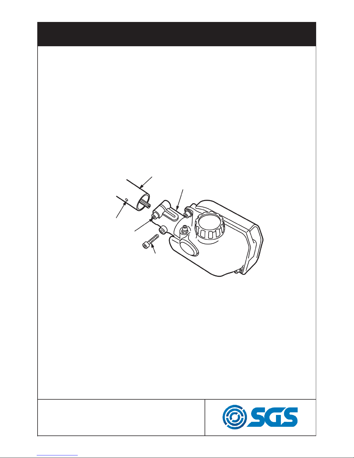
ATTACHING THE TRIMMING MECHANISM
Attachment
tube
Screw
hole
Fastening
bolt
Screw
Gear
case
(Instructions to follow on page 10)
WWW.SGS-ENGINEERING.COM
CALL FOR ASSISTANCE: 01332 576 850
PAGE 17
SET UP
1. Remove the plastic cap on the end of the tube.
2. Remove the screw.
3. Insert the end of the tube into the gear case, and make sure
to align the transmission shaft of the tube with the transmission
shaft of the gear case.
4. Line up the hole on the tube with the hole on the gear case
and insert the screw through the hole and tighten firmly.
ATTACHING THE PRUNING MECHANISM
Attachment tube
Bolt hole
Fastening bolt
Bolt
Gear case
1. Remove the plastic cap on the end of the tube.
2. Remove the bolt.
3. Insert the end of the tube into the gear case, make sure to
align the transmission shaft of the tube with the transmission
shaft of the gear case.
4. Line up the hole on the tube with the hole on the gear
case and insert the bolt through the hole and tighten firmly.
5. Using a wrench, screw in the fastening bolt provided to fix
the mechanism into place.
PAGE 18
SET UP
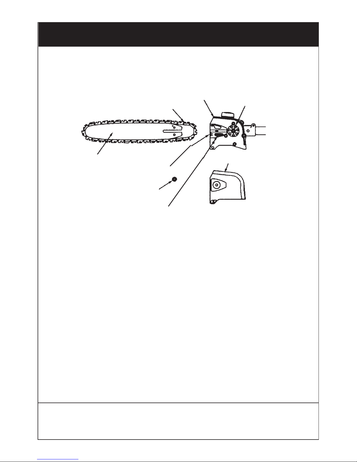
INSTALLING GUIDE BAR AND SAW CHAIN
Guide bar
Saw chain
Transmission
Sprocket
Chain tension adjust screw
Nut
Chain tensioner nut
Chain cover
1. Loosen the nut and remove the chain cover.
2. Mount the guide bar, then fit the saw chain around the bar
and sprocket.
3. Fit the chain tensioner nut into the lower hole of the guide
bar, then install the chain cover, and fasten the mounting nut
to finger tightness.
4. Adjust the chain tension by turning the tensioner screw
until the tie straps just touch the bottom side of the bar rail.
5. Tighten the mounting nut securely with the bar tip held
up (TORQUE: 8.9 ~ 11.7 N.m./90 ~ 120 kg-cm). Then check
the chain for smooth rotation and correct tension while moving it by hand. If necessary, readjust.
WWW.SGS-ENGINEERING.COM
CALL FOR ASSISTANCE: 01332 576 850

PAGE 19
ASSEMBLY
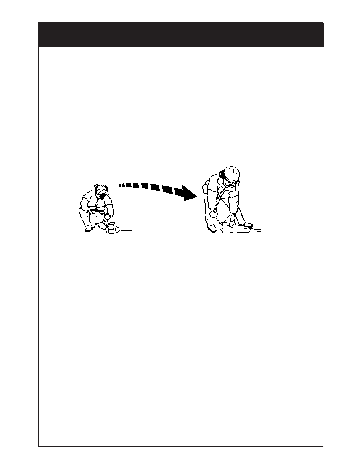
Balancing the strimmer
1. Put the harness on and attach your strimmer to it.
2. Slide clamp up and down, till you feel comfortable with how
the strimmer balances, and how you can manoeuvre it whilst
working.
Make sure the strimmer unit is off, whilst doing
this procedure, to ensure accurate balancing.
PAGE 20
• Always use a fuel container with an anti-spill valve.
• Never refuel the machine while the engine is running.
• Always stop the engine and let it cool for a few minutes before refilling with mixed fuel.
• Make sure there is plenty of ventilation when refilling or mixing fuel (petrol and 2--stroke oil).
• Move the machine at least 10 feet (3 meters) from the refueling point before starting it.
Never start the machine:
• If you have spilt fuel on it. Wipe off the spillage and allow
remaining fuel to evaporate.
• If you have spilt fuel on yourself or your clothes, change your
clothes. Wash any part of your body that has come in contact
with fuel. Use soap and water.
• If the machine is leaking fuel. Check regularly for leaks from
the fuel cap and fuel lines.
• Avoid all skin contact with fuel. Fuel is a skin irritant.
FUEL SAFETY
WWW.SGS-ENGINEERING.COM
CALL FOR ASSISTANCE: 01332 576 850
 Loading...