

Page 1
150L BELT DRIVE
AIR COMPRESSOR
OWNER’S MANUAL
FOR YOUR SAFETY
PLEASE READ THESE INSTRUCTIONS CAREFULLY
AND RETAIN THEM FOR FUTURE USE.
Page 2
SPECIFICATION
ITEM DATA
Model SC90B SC150B
Power 2200W / 3 HP
Voltage 230 V
Frequency 50 Hz
Delivery 14 CFM
Max Discharge Pressure 150 PSI / 10 BAR
Tank Capacity 90 L 150 L
Dimensions
990 x 440 x 880 mm 1400 x 475 x 890 mm
Oil / Oil Free Oil Lubricated
Wheel Mounted Yes
Air Outlets 2
Air Outlet Size 1/4”
Net Weight 69 kg 81 kg
Noise Information LWA 97 dB
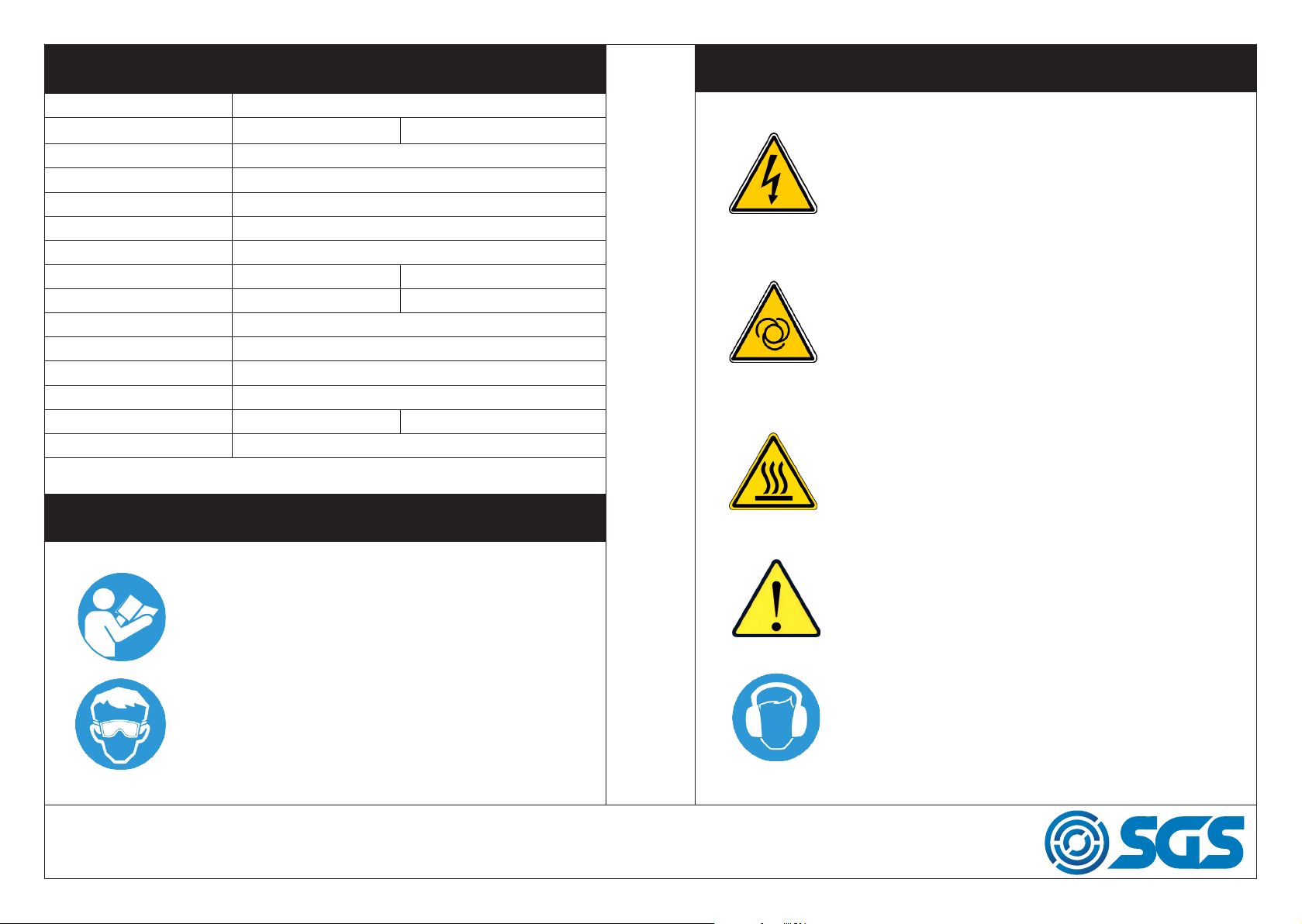
WARNING
WARNING
Risk of electric shock. The compressor must be disconnected from the mains supply before maintenance or removing any covers. Do not use in a damp environment.
Risk of accidental start-up. The compressor could start
automatically in the event of a power cut and subsequent reset. Do not carry the compressor while it is connected to the power source, or when the tank is filled
with compressed air.
This compressor contains surfaces which may reach a
high temperature during operation. Never operate with
the motor housing removed.
Read and understand instructions before use.
Always wear eye/face and hand protection.
WWW.SGS-ENGINEERING.COM
PAGE 2
Air and condensation water can burst from the compressor when the drain plug is removed.
This compressor produces a high sound level during
operation. Ear protection should be worn.
PAGE 3
Page 3

SAFETY PRECAUTIONS
SAFETY PRECAUTIONS
KEEP VISITORS/CHILDREN AWAY: Do not allow visitors/children to handle the air compressor or attachments and ensure that any people in the
work area are suitably dressed.
KEEP THE WORK AREA CLEAN: Cluttered areas mean accidents, so
clear the work area of all unnecessary tools, debris and furniture.
DO NOT TOUCH HOT SURFACES: During operation, the motor, connections, compressor body, cylinder head and tubes may get hot, do not
touch.
DO NOT DIRECT AN AIR STREAM AT THE BODY: Do not direct the
air stream at people or animals, as injury may result. Compressed air
can cause soft tissue damage and propel dirt and other particles at high
speed.
BREATHING AIR: This compressor should not be used to supply breathing quality air. Never use it as breathing apparatus.
STAY ALERT: Watch what you are doing, use common sense, and do not
operate the air compressor when you are tired. The air compressor should
not be used if you are under the influence of alcohol, drugs or any medi-
cation that makes you drowsy.
DISCONNECT THE AIR COMPRESSOR: Always disconnect the air compressor from the mains power supply and decompress before performing
maintenance, changing any parts and when not in use.
MAINS POWER CABLE PRECAUTIONS: Never pull on the cable when
removing the plug from the mains socket, or lift the compressor by the
mains cable.
AVOID UNINTENTIONAL STARTING: When connecting the air compressor to the mains supply make sure the red button on top of the air compressor is in the OFF (down) position.
STORE THE AIR COMPRESSOR PROPERLY: When not in use the air
compressor should be stored in a secure, dry place out of the reach of
children. Always lock up the storage area.
MAINTAIN THE AIR COMPRESSOR WITH CARE: If the air compressor is
damaged in any way, have it repaired by a qualified engineer.
DO NOT USE EXTENSION LEADS: Using extension leads can cause your
compressor motor to burn out. Only use extension hoses.
DO NOT WELD TO THE PRESSURE VESSEL
Do not weld or modify the pressure vessel in any manner.
DISPOSAL INFORMATION
The air compressor should be disposed of in a safe an environmentally
friendly manner. Contact your local Council for disposal assistance.
WWW.SGS-ENGINEERING.COM
PAGE 4
PAGE 5
Page 4
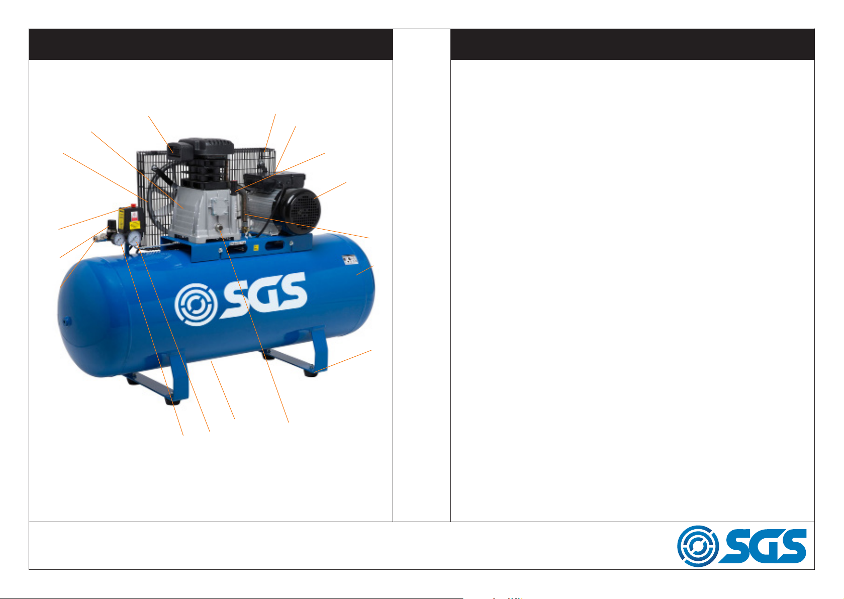
QUICK REFERENCE
QUICK REFERENCE
15
14
13
12
16
17
1
2
3
4
5
6
7
1. Guard
2. Capacitor / motor control box
3. Oil breather plug
4. Motor unit
5. Air delivery pipe
6. Air reciever
7. Feet
8. Oil sight glass
9. Drain valve
10. Air reciever pressure gauge
11. Regulated air outlet pressure gauge
12. Air outlet (regulated pressure)
13. Pressure regulator
14. On / off switch
15. Flywheel / fan
WWW.SGS-ENGINEERING.COM
11
10
9
8
PAGE 6
16. Pump unit
17. Air intake filter
PAGE 7
Page 5

SETTING UP THE COMPRESSOR
SETTING UP THE COMPRESSOR
IMPORTANT! Before starting the machine remove all the
travel plugs and attach the Air Filter and the Crank Case
Breather Plug.
The compressor is
equipped with a safety
valve. If the pump were to
continue operating above
the maximum pressure,
the safety valve would
open and eject air from
the vessel. If the safety
valve discharges air, please turn off the compressor and contact the hel-
pline. The safety valve is located to the side of the pressure switch.
Filling the sump with oil
Pour approximately 0.5L of oil into the sump until the oil level reaches the
red spot in the centre of the sight glass (see image below). Once the oil
has reached the correct level re-insert the oil breather plug.
WWW.SGS-ENGINEERING.COM
PAGE 8
PAGE 9
Page 6

OPERATION
OPERATION
Air Pressure Regulator
To adjust the pressure turn the Pressure
Regulator dial anti clockwise to decrease
the pressure and turn the dial clockwise
to increase pressure.
On / off switch
Pressure regulator
Output pressure gauge
Outlet valves
Starting the Air Compressor
Once the air compressor is connected to the mains supply use as follows:
a) Pull up the button on the pressure switch this will ‘click’ up into posi-
tion. The motor/pump will now start to run.
b) Check that the motor/pump automatically stops when the pressure
inside the air receiver reaches approximately (10BAR) (check gauge). Ro-
tate the air regulator to the desired outlet pressure and plug in hose with
chosen air tool connected to the other end. The air is now ready for use.
You may need to finely adjust as the air tool is used.
c) Check that the motor/ pump automatically starts, when the pressure
falls by approximately 2BAR.
When the compressor is running correctly you will hear the following:
a) When the air compressor starts from no pressure within the tank there is
a whistle of ‘leaking’ air from the pressure switch for about 20-30 seconds.
b) Whenever the motor stops there will be a quick sudden discharge of
air. (This is the motor start and stop air unloading system being activated).
WWW.SGS-ENGINEERING.COM
PAGE 10
Shutting down the Air Compressor
Never stop the compressor by unplugging it. The pressure switch must
always be used as this ensures that air is discharged from the head. This
makes the starting easier for the motor and prevents motor damage.
PAGE 11
Page 7

TROUBLESHOOTING
PROBLEM POSSIBLE CAUSE ACTION
Motor unable to run,
running slow or getting
hot
Sticking of main compressor
Shaking or abnormal
noise
Pressure insufficient
or discharge capacity
decreased
1. Fault in line or insufficient
voltage
2. Power wire too thin or long
3. Fault in pressure switch
4. Fault in motor
5. Sticking of main compressor
1. Moving parts burnt due to
insufficient oil
2. Moving parts damaged or
stuck by a foreign body
1. Connecting part loose
2. Foreign body in the main
compressor
3. Piston knocking the valve
seat
4. Moving parts seriously
worn
1. Motor running too slow
2. Air filter choked up
3. Leakage of safety valve
4. Leakage of discharge pipe
5. Sealing gasket damaged
6. Valve plate damaged,
stuck or carbon build up
7. Piston ring and cylinder
worn or damaged
1. Check the line
2. Replace the wire
3. Repair or replace
4. Repair or replace
5. Check and repair
Check crankshaft, bearing,
connecting rod, piston, piston ring,
etc. and replace if
necessary
1. Check and retighten
2. Check and clean away
3. Replace with thicker paper
gasket
4. Repair or replace
1. Check and remedy
2. Clean or replace the cartridge
3. Check and adjust
4. Check and repair
5. Check and replace
6. Replace and clean
7. Repair or replace
MAINTENANCE
Changing the oil
Switch off the motor and remove the power plug from the socket outlet.
Release any remaining air pressure and then unscrew the oil drain plug
from the compressor pump and remove. Direct the oil into an appropriate
container. If any oil still remains, tilt the compressor slightly. When all the
old oil has been removed, screw the oil drain plug into place.
Cleaning
Clean the items with a soft brush or a wipe moistened with a suitable bio-
degradable solvent. Do not use flammable liquids like petrol or alcohol,
they are a risk and will damage the finish and plastic parts.
Cleaning/ changing the air filter (Monthly)
Please note: This compressor should not be used in a heavily dusty atmos-
phere. The warranty does not cover damage caused by a blocked air filter.
The air filter must be cleaned or replaced monthly, or more frequently if
the compressor is in regular use. The air filter can be accessed easily by
unscrewing the air filter cover (wing nut) at the side of the pump.
Excessive oil consumption
1. Oil level too high
2. Breather pipe choked up
3. Piston ring and cylinder
WWW.SGS-ENGINEERING.COM
worn or damaged
1. Keep the level within set range
2. Check and clean
3. Repair or replace
PAGE 12
PAGE 13
Page 8

ADJUSTING THE CUT OFF PRESSURE
ADJUSTING THE CUT OFF PRESSURE
If your compressor cuts out before 10 bar:
Your compressor has been tested during manufacture and the cut off
pressure may be set at 6 bar or 8 bar, rather than 10 bar.
Most applications do not require 10 bar air pressure so we recommend
leaving the cut off pressure at the factory setting unless explicitly required.
If you wish to increase the tank pressure to 10 bar first open the switch
box by unscrewing the single screw:
Then turn the 10mm nut clockwise to increase the pressure and counter-
clockwise to decrease the pressure. Make a half turn on the nut in either
direction, then wait for the tank pressure to equalise. Make further half
turns if required.
WWW.SGS-ENGINEERING.COM
PAGE 14
PAGE 15
Page 9

PARTS DIAGRAM PARTS LIST
NO. Description QTY Part No NO. Description QTY Part No
1 Motor Group 1 902689 21 Check Valve 1 902709
2 Pump 1 902690 22 Nut 1 902710
3 Screw 2 902691 23 Aluminum Pipe 1 902711
4 Cylinder Cover 1 902692 24 Tank 1 902712
5 Screw 2 902693 25 Screw 4 902807
6 Air Filter 1 902694 26 Plain Washer 4+5 902808
7 Nut 16 902695 27 Foot Pad 4 902809
8 Screw 4 902696 28 Drain Cock 1 902716
9 Connector 1 902697 29 Pump Board 1 902810
10 Pressure Gauge 1 902698 30 Screw 8 902718
11 Pressure Regulator 1 902699 31 Plain Washer 4 902811
12 Pressure Gauge 1 902700 32 Gasket 4 902812
13 Pressure Switch 1 902701 33 Nut 4 902813
14 Quick Coupler 2 902702 34 Belt 1 902723
15 Safety Valve 1 902703 35 Screw 5 902724
16 Power Wire 1 902704 36 Belt Cover 1 902726
17 Screw 2 902705 37 Screw 1 902727
18 Copper Pipe 1 902706 38 Belt Cover Support 2 902728
19 Cooling Fin 1 902707 39 Elbow 1 902729
20 Elbow 1 902708
WWW.SGS-ENGINEERING.COM
PAGE 16
PAGE 17
Page 10

PARTS DIAGRAM PARTS LIST
NO. Description QTY Part No NO. Description QTY Part No
1 Key 1 902732 20 Gasket 25 902751
2 Motor Wheel 1 902733 21 Nut 11 902752
3 Screw 6 902734 22 Screw 2 902753
4 Washer 6 902735 23 Capacitor 1 902754
5 Washer 6 902736 24 Capacitor 1 902755
6 Front Cover 1 902737 25 Screw 4 902756
7 Gasket 1 902738 26 Wire 1 902757
8 Bearing 2 902739 27 Screw 5 902758
9 Gasket 1 902740 28 Washer 4 902759
10 Screw 2 902741 29 Gasket 1 902760
11 Gasket 1 902742 30 Gasket 1 902761
12 Centrifugal Switch 1 902743 31 Protector 1 902762
13 Rotor 1 902744 32 Unseparated Device 1 902763
14 Stator 1 902745 33 Wire 1 902764
15 Capacitor Cover 1 902746 34 Rear Cover 1 902765
16 Support 2 902747 35 Fan 1 902766
17 Gasket 1 902748 36 Gasket 1 902767
18 Wire Support 1 902749 37 Motor Cover 1 902768
19 Gasket 2 902750 38 Screw 3 902769
WWW.SGS-ENGINEERING.COM
PAGE 18
PAGE 19
Page 11

PARTS DIAGRAM PARTS LIST
NO. Description QTY Part No NO. Description QTY
1 Cylinder Head Bolt 6 902770 19 Oil Gauge 1
2 Cylinder Head 1 902771 20 Seal Ring 1
3 Cylinder Head Gasket 1 902772 21 Screw 1
4 Valve Plate 2 902773 22 Bottom Board 1
5 Gasket 1 902774 23 Screw 12
6 Valve 4 902775 24 Piston Ring 2
7 Pin 2 902776 25 Piston 2
8 Valve Plate gasket 1 902777 26 Circlip 4
9 Cylinder 1 902778 27 Piston Pin 2
10 Cylinder Gasket 1 902779 28 Connecting Rod 2
11 Crankcase 1 902780 29 Gasket 8
12 Screw 8 902781 30 Cylinder Screw 8
13 Gasket 8 902782 31 Oil Seal 1
14 Rear Cover 1 902783 32 Front Cover 1
15 Gasket 2 902784 33 Belt Wheel 1
16 Bearing 2 902785 34 Washer 1
17 Crankshaft 1 902786 35 Screw 1
18 Oil Breath 1 902787
Part No
902788
902789
902790
902791
902792
902793
902794
902795
902796
902797
902798
902799
902800
902801
902802
902803
902804
WWW.SGS-ENGINEERING.COM
PAGE 20
PAGE 21
Page 12

SGS Engineering (UK) Ltd
West Side Park
Derby, DE21 7AZ
EC Declaration of Conformity
This is an important document and should be retained
Raynesway
MANUFACTURER’S NAME:
TYPE OF EQUIPMENT:
PART NUMBER:
APPLICATION OF EC COUNCIL DIRECTIVES / STANDARD:
SGS Engineering (UK) Ltd
AIR COMPRESSOR
SC90B & SC150B
2006/42/EC - Machinery
2004/108/EC - EMC
2006/95/EC - LVD
87/404/EEC - The simple pressure vessel regulations
97/23/EC - Pressure equipment directive
I, the undersigned, hereby declare that the equipment specied above
conforms to the above European Communities Directive(s) and
Standard(s).
PLACE:
Derby, UK
DATE:
24th MAY 2018
(Signature)
Robert Wyatt
Company Secretary
 Loading...