

Page 1
FOR YOUR SAFETY
PLEASE READ THESE INSTRUCTIONS CAREFULLY
AND RETAIN THEM FOR FUTURE USE.
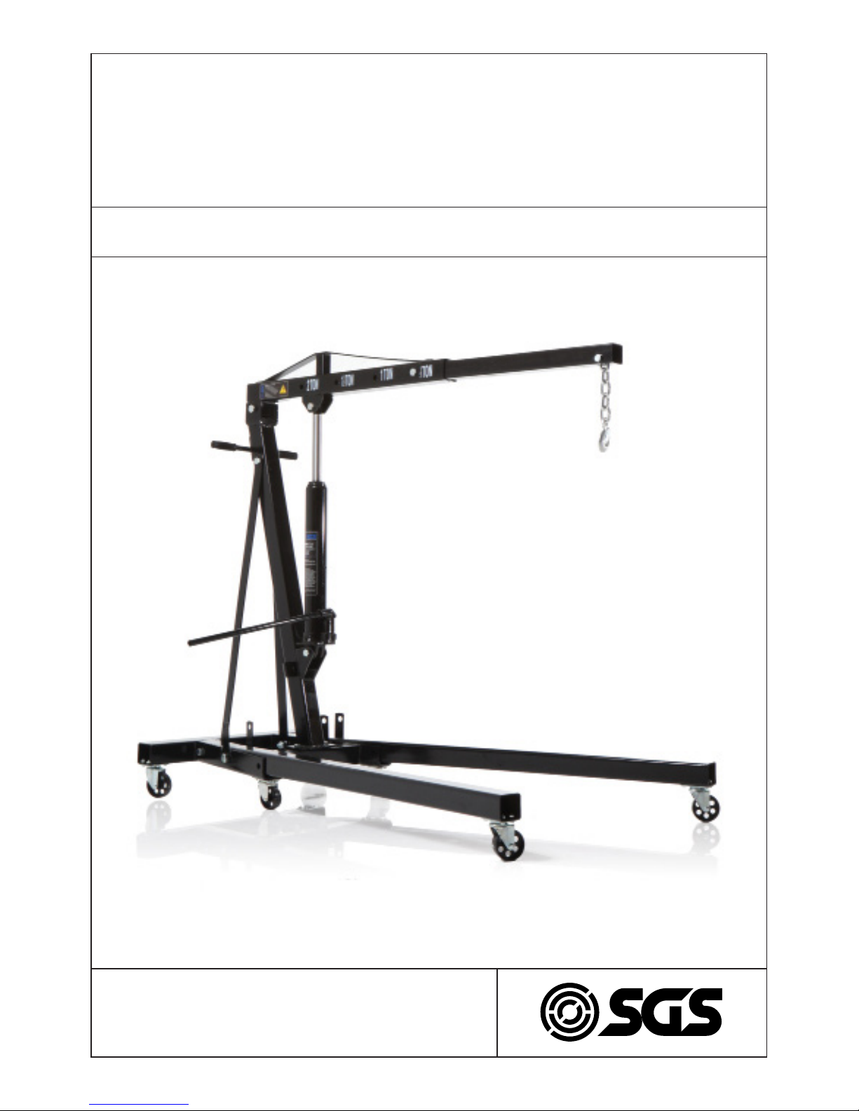
OWNER’S MANUAL
EC2000
ENGINE CRANE
2 TONNE MAX CAPACITY
Page 2

WARNING
Do not overload. Overloading could cause damage or failure of the crane. Never exceed the safe working loads indicated on the jib.
Never use the crane on an uneven floor surface as this could result in the crane tipping over.
Always lock the legs and jib in position before lifting a load.
The nuts and bolts supplied with the crane are all high strength and should not be
substituted for inferior types. Before each use ensure that all nuts and bolts are correctly fitted and tight.
WARNING: This double pump long ram is designed for lifting purposes only – not for
supporting loads. Do not load beyond its rated capacity.
IMPORTANT: It is possible that air has got into the hydraulic system causing poor
lifting performance. Purge any air from the system by fully opening the release valve
(turn handle counter-clockwise) then while holding the boom down operate the pump
handle rapidly several times.
Note: Before raising the legs to the storage position bolts must be inserted into the
base support and tightened each time. If this procedure is not followed the unit may
fall over.
MAINTENANCE
IMPORTANT: When adding or replacing oil always use high grade hydraulic jack oil.
Avoid mixing different grades/types of oil. Do not use brake fluid, alcohol, glycerine,
detergent motor oil or dirty oil. Improper fluid can cause serious internal damage to
the ram.
When adding oil be very careful not to permit dirt or foreign matter to enter the system. Check ram and plunger every 3 months for any signs of rust or corrosion. Clean
as needed and wipe with an oily cloth.
When not using the ram always leave the jib in the fully lowered position.
WWW.SGS-ENGINEERING.COM
PAGE 2
Page 3
OPERATING INSTRUCTIONS
TO RAISE LOAD: Close release valve by turning handle clockwise to a snug-tight posi-
tion. Do not over-tighten.
TO LOWER LOAD: Open release valve by turning handle counter-clockwise very
slowly. The speed of the lowering is controlled by how much the handle is turned.
TROUBLE SHOOTING
TROUBLE PROBABLE CAUSE REMEDY
Will not hold load. Dirt on valve seats. 1. Lower lifting boom. Close the
release valve and remove oil
filler plug.
2. Place one foot on the leg and
pull up the lifting boom to its
full height by hand.
3. Open the release valve to lower
the lifting boom.
4. Replace worn seals.
Will not lift load.
Will not lift to its full height.
Pump feels unsteady under
load. Pump will not lower
completely.
Air block. 1. Open the release valve and
remove oil filler plug.
2. Pump handle a couple of full
strokes and close the release
valve.
Pump will not lift to its full
height. Pump feels unsteady
under load.
The reservoir could be overfilled. Low hydraulic oil level.
Check the oil level. Remove the filler
plug.
Top up oil to correct level.
Pump feels unsteady under
load.
The cup seal could be worn
out.
Replace cup seal.
Will not lower completely. Air block. Unit requires
lubrication.
Release air from the hydraulic pump
by removing filler plug.
Oil external moving parts.
PAGE 3
Page 4

ITEM DESCRIPTION QTY
H1 SPRING WASHER 8 24
H2 NUT M8 16
H3 BOLT M8X20 16
H4 BOLT M8X12 8
H5 BOLT M14X95 2
H6 WASHER 14 3
H7 NUT M14 3
H8 SPRING WASHER 16 2
H9 NUT M16 6
H10 BOLT M16X100 1
H11 BOLT M16X115 2
H12 BOLT M18X125 2
H13 SPRING WASHER 18
2
H14
NUT M18 3
H15 PIN 18X110 2
H16 SPLIT PIN 2
H17 BOLT M16X90 2
H18 WASHER 16 4
H19 BOLT M18X110 1
H20 WASHER 18 1
H21 BOLT M16X75 1
H22 BOLT M14X75 1
WWW.SGS-ENGINEERING.COM
PAGE 4
Page 5

ITEM DESCRIPTION QTY
1 BASE 1
2 LARGE CASTER 4
3 SMALL CASTER 2
4 POST 1
5 SUPPORT 2
6 LEG 2
7 JACK 1
8 BOOM 1
9 EXTENSION 1
10 JACK HANDLE 1
11 CHAIN/HOOK 1
PAGE 5
Page 6

ITEM DESCRIPTION QTY
1 VALVE BLOCK 1
2 COPPER WASHER 1
3 CYLINDER 1
4 O-RING 1
5 O-RING RETAINER 1
6 RAM 1
7 TOP NUT 1
8 O-RING 1
9 SEALING GASKET 1
10 OIL TANK 1
11 OIL PLUG 1
12 SEAL RING 1
13 TUBE 1
14 BOLT 1
15 SCREW 2
16 BALL 1
17 SEAL RING 1
18 RELEASE SPINDLE 1
19 BALL 1
20 COPPER WASHER 1
21 PUMP CYLINDER 1
22 O-RING 1
23 BACK UP RING 1
24 PLUNGER 1
25 PUMP LINK 1
26 HANDLE 1
27 HANDLE SOCKET 1
28 SHAFT 2
29 COTTER PIN 2
FOR YOUR SAFETY
PLEASE READ THESE INSTRUCTIONS CAREFULLY
AND RETAIN THEM FOR FUTURE USE.
Page 7

EC Declaration of Conformity
This is an important document and should be retained
MANUFACTURER’S NAME:
TYPE OF EQUIPMENT:
PART NUMBER:
I, the undersigned, hereby declare that the equipment specied above
conforms to the above European Communities Directive(s) and
Standard(s).
PLACE:
DATE:
(Signature)
Robert Wyatt
Company Secretary
Derby, UK
24th JUNE 2017
SGS Engineering (UK) Ltd
SGS Engineering (UK) Ltd
West Side Park
Raynesway
Derby, DE21 7AZ
Engine Crane
EC2000
EN 1494:2000+A1:2008 Mobile or movable jacks and
associated lifting equipment
EN ISO 12100:2010 Risk assessment & risk reduction
EN ISO 13857:2008 Safety distances & hazard zone
EN 349:1993+A1:2008 Minimum safety gaps
2006/42/EC Machinery Directive (MD)
APPLICATION OF EC COUNCIL DIRECTIVES / STANDARD:
 Loading...