

SFA SANISPEED User Manual

PUMP
Distribuitor: CALOR SRL
Str. Progresului nr. 30-40, sector 5, Bucuresti
tel: 021.411.44.44, fax: 021.411.36.14
www.calorserv.ro - www.calor.ro
1
04.12
IND1
DE
UK
FR
PUMP 1
PUMP 2
geprüfte
Sicherheit
TR
CZ
RO
RU
NO
DK
SV
NL
PTESIT
PLFI
HU
CN
433
10 2200 30 40 50 60 70 80 90 100 110 120
8
7
6
5
4
3
2
1
0
1
04.12
IND1
1
SFA
2
5
7
7a
3
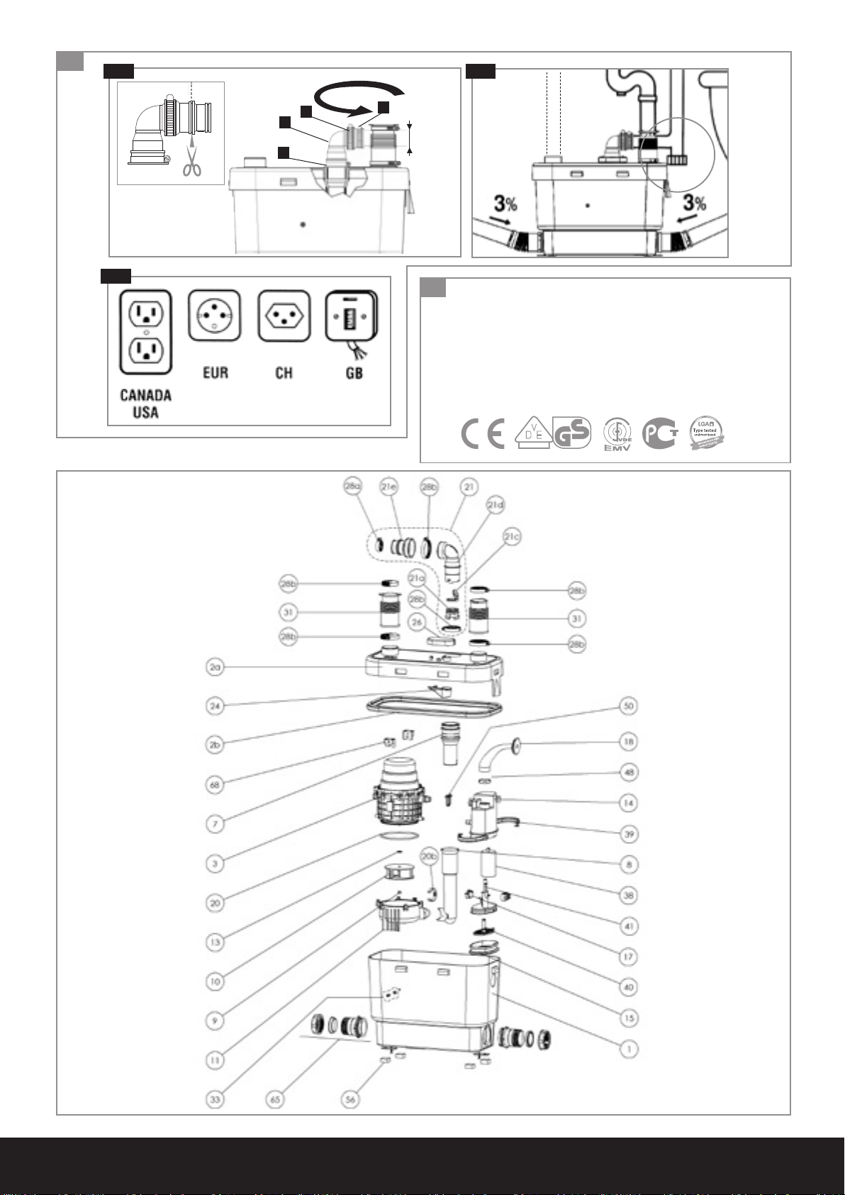
max 7m
6m
5m
4m
3m
2m
1m
1
%
max 10 m
1
%
max 20 m
1
%
max 30 m
1
%
max 40 m
1
%
max 50 m
1
%
1
%
max 60 m
max 70 m
1
OK
2 3
A
G
32 x 50
x 8
x 1
B
D
H
x 2
x 3
C
x 1
F
I
x 2
Ø 32
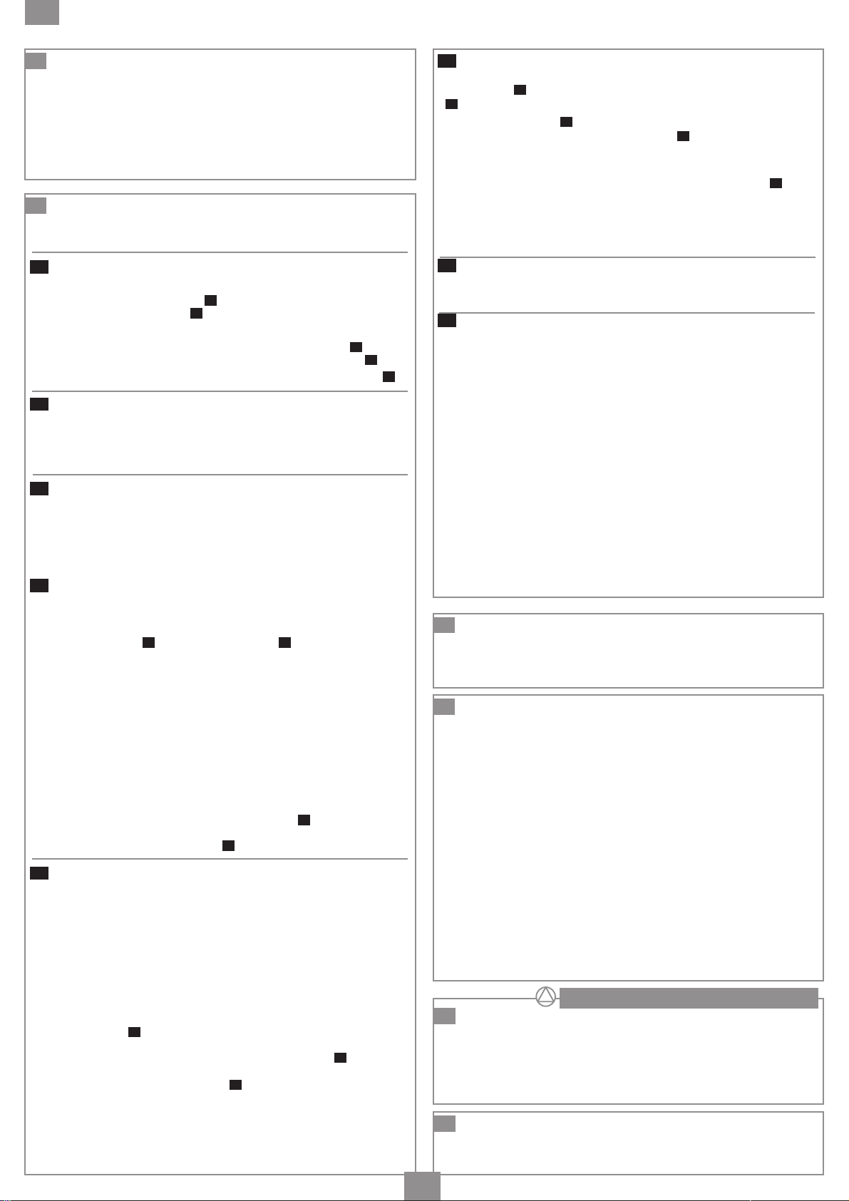
Hauteur (m) • Vertical Height (m)
Fôrdenhöhe (m) • Altezza (m)
Opvoercapaciteit (m) • Altura (m)
Pumphöjd (m) • Løftehøjde (m)
Pumpehøyde (m) • Magasság (m)
Wydajność (m) pionowa • ⁄„o˜ (m) • Korkeus
(m) Altura (m) • Высота подъема (м) •
Débit (l/min) • Flow Rate (l/mn) • Förderstrom (l/min) • Portata (l/min)
• Afvoercapaciteit (l/min.) • Caudal (l/min) • Vattenmängd (l/min) •
Vandmængde (l/min) • ¶·Úo¯‹ (l/min) • Vannmengde (l/min) •
Átfolyás (l/min) • Wydajność (l/min) • Virtaus (l/min) • Caudal (l/min) •
Пропускная способность (л/мин) •
H
H
I
I
x 2
x 1
25 x 40
6
G B G
7c7b
G
B
G
1
4
C
®
SFA SANISPEED
geprüfte
Sicherheit
7
Type tested
and monitored
7d
7e
7f
G
A
G
F
Ø 32 mm
8
SANISPEED
®
Société Française d’Assainissement
EN 12050-2
FF02-V45
220-240 V - 50 Hz - 400 W - IP44 - 2 A
6,4 KG
geprüfte
Sicherheit
SFA SANISPEED
®

NOTICE D’INSTALLATION ............................................................................................................................................................................................................................................................................................................................... p. 3
FR
INSTALLATION INSTRUCTIONS
UK
INSTALLATIONSHINWEISE
DE
ISTRUZIONI PER L’INSTALLAZIONE
IT
MANUAL DE INSTALACIÓN
ES
MANUAL DE INSTALAÇÃO
PT
INSTALLATIE VOORSCHRIFTEN
NL
INSTALLATIONS - OCH SKÖTSELANVISNING
SV
INSTALLATIONSVEJLEDNING
DK
.................................................................................................................................................................................................................................................................................................. p. 4
.......................................................................................................................................................................................................................................................................................................................... p. 5
........................................................................................................................................................................................................................................................................ p. 6
....................................................................................................................................................................................................................................................................................................................... p. 7
........................................................................................................................................................................................................................................................................................................................... p. 8
................................................................................................................................................................................................................................................................................................ p. 9
.......................................................................................................................................................................................................................................................................................... p. 11
........................................................................................................................................................................................................................... p. 10
INSTALLASJONSVEILEDING
NO
ASENNUSOHJEET
FI
INSTRUKCJA INSTALACJI
PL
ИНСТРУКЦИЯ ПО УСТАНОВКЕ
RU
RO
MANUAL DE INSTALARE
CZ
NÁVOD K INSTALACI A POUŽÍVÁNÍ
TR
KURULUM KILAVUZU
HU
TELEPÍTÉSI KÉZIKÖNYV
...................................................................................................................................................................................................................................................................................................................................................................... p. 13
......................................................................................................................................................................................................................................................................................................................................................... p. 18
............................................................................................................................................................................................................................................................................................................................................ p. 19
............................................................................................................................................................................................................................................................................................... p. 12
............................................................................................................................................................................................................................................................................................................................. p. 14
............................................................................................................................................................................................................................................................................................... p. 15
.................................................................................................................................................................................................................................................................................................................................... p. 16
....................................................................................................................................................................................................................................................................................... p. 17
CN
用户应保留安装指南以备用 .......................................................................................................................................................................................................................................................................................................... p. 20
2
FR
1
AVERTISSEMENT
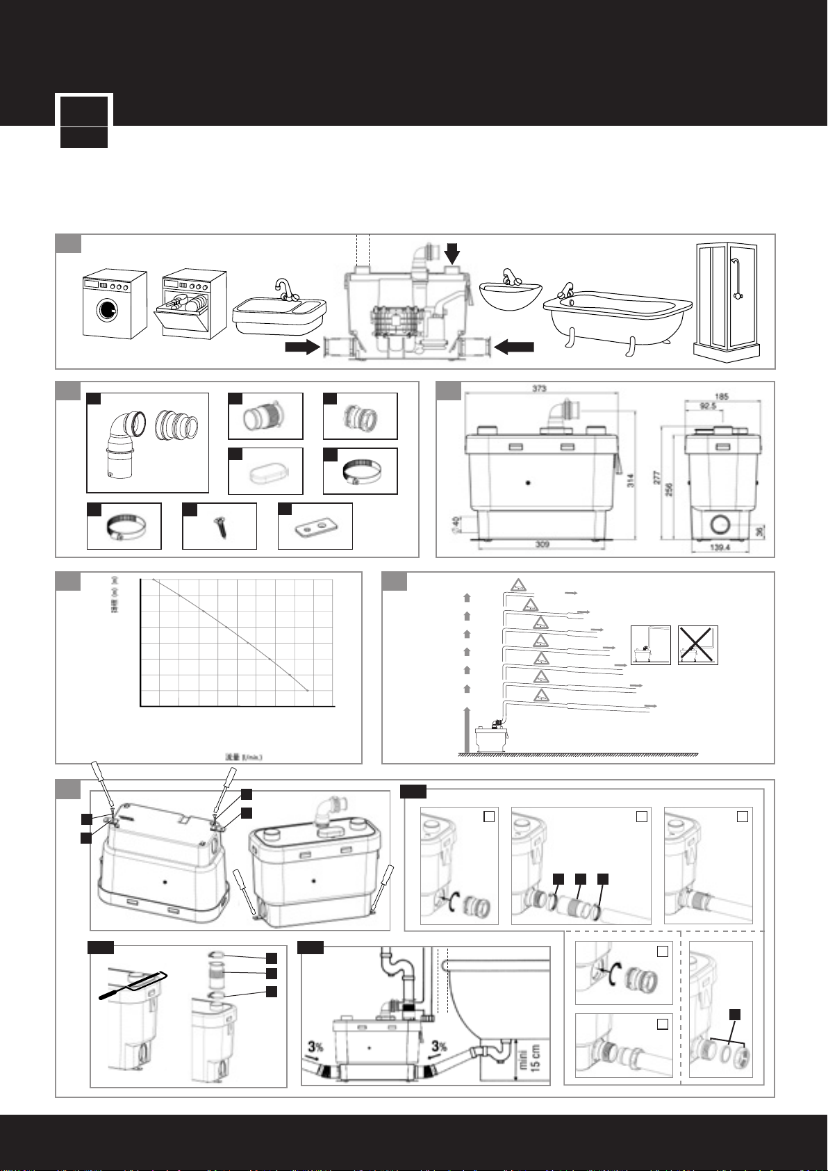
Cet appareil est une pompe de relevage pour eaux usées
provenant d’une douche et d’un lavabo.
Il démarre automatiquement. Les appareils SANIVITE®,
SANISPEED® et SANIPUMP 2® peuvent également relever les
eaux usées de buanderies, d’éviers, de machine à laver le linge
ou lave-vaisselle domestiques et de baignoire.
7
INSTALLATION
L’appareil doit être d’accès aisé pour le contrôle et la maintenance.
La pompe possède des dispositifs de fixation l’empêchant de tourner
ou de bouger.
7a
RACCORDEMENT AUX ENTREES LATERALES
(appareils SANIVITE®, SANISPEED® et SANIPUMP 2®)
Pour les raccordements aux entrées latérales de la cuve:
1) Connecter le raccord
au manchon
C
B
à la cuve, puis relier le tube d’entrée grâce
et aux 2 colliers G : vues 1, 2 et 3.
ou
2) Connecter le raccord
d’entrée à ce raccord
Boucher les entrées non utilisées grâce au bouchon du raccord
7b
RACCORDEMENT A L’ENTREE COUVERCLE
C
à la cuve, puis relier directement le tube
C
: vues 1 et 4
C
.
(appareils SANIVITE®, SANISPEED® et SANIPUMP 2®)
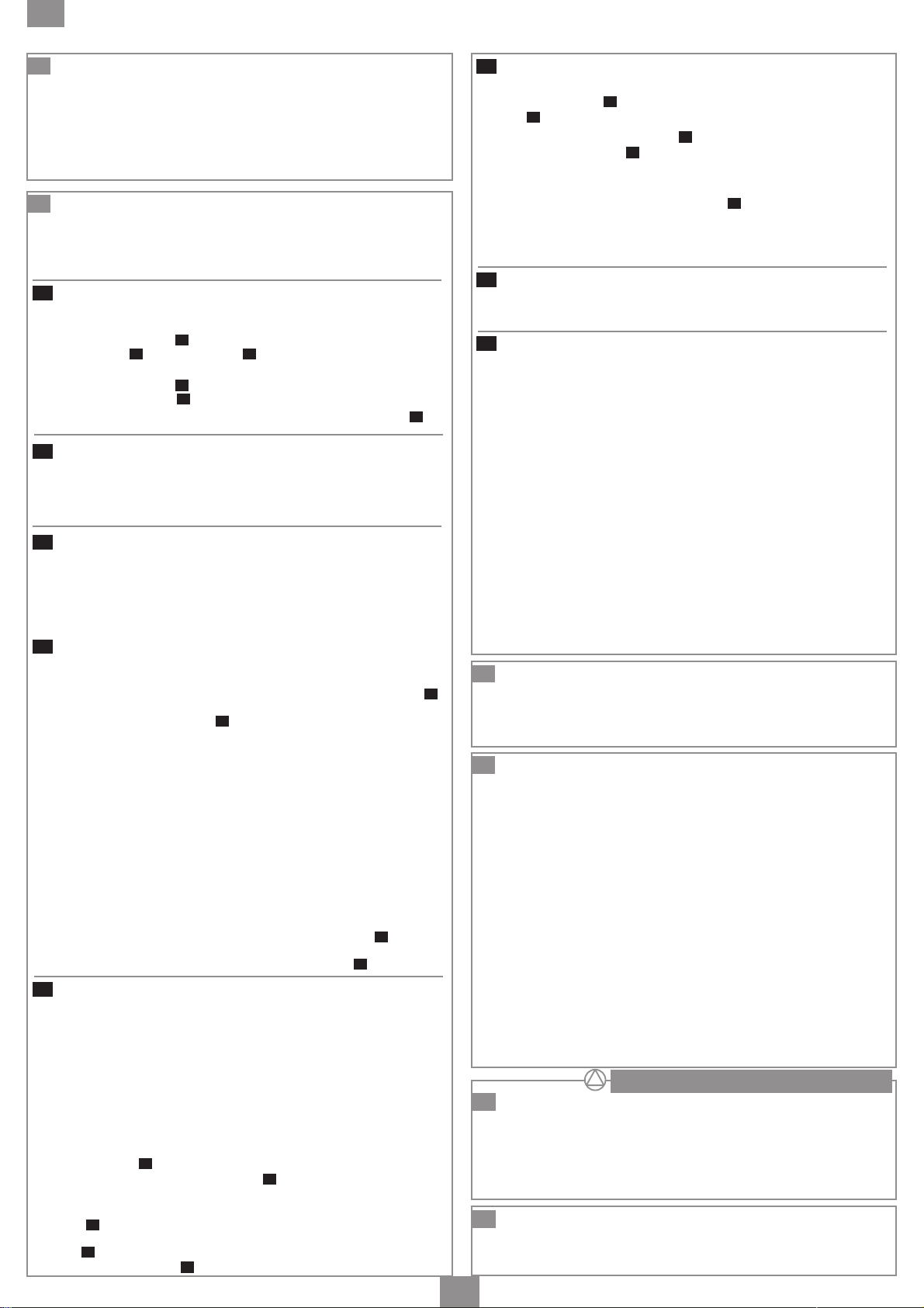
Pour utiliser l’entrée du couvercle, scier et ébarber la calotte
supérieure à droite puis raccorder avec un manchon. Le fixer
avec les colliers.
7c
RACCORDEMENT AUX APPAREILS SANITAIRES
(appareils SANIVITE®, SANISPEED® et SANIPUMP 2®)
Pour raccorder une baignoire (ou une douche), veiller à surélever
le fond d’au moins 15 cm. Bien que normalement pas nécessaire,
une ventilation (en pointillé sur le dessin) peut être raccordée sur
une gaine de ventilation. (calotte gauche sur le couvercle)
7c
RACCORDEMENT AUX APPAREILS SANITAIRES
(appareil SANIDOUCHE® et SANIPUMP 1®)
• Installation à côté du receveur de la douche (conformément à
la norme NF-C15100) : raccorder une extrémité du manchon
à l’entrée basse de l’appareil et l’autre à un tube DN 40 mm.
Le fixer à l’aide des colliers
B
.
A
Attention : veillez à ce que l’évacuation de la bonde de la douche
soit au moins à 60 mm du sol.
• Installation sous le receveur de la douche : Surélever le
receveur d’au moins 145 mm pour loger l’appareil.
Attention : prévoir une trappe d’accès à l’appareil de dimension
mini L=400 mm H=145 mm. L’ouverture de cette trappe doit
nécessiter un outil.
• Raccordement de l’entrée optionnelle
- A l’aide d’un cutter, découper avec soin l’opercule choisi. Veiller
à ne pas faire d’entaille à angle vif et bien ébavurer.
Attention : le trou découpé doit être parfaitement lisse pour
que la liaison soit étanche.
- Couper si nécessaire l’extrémité du manchon étagé
en DN 40. Insérer la gorge du manchon dans le trou de la
cuve. Raccorder le tube et le fixer avec le collier
7d
RACCORDEMENT A L’EVACUATION
B
G
.
(appareils SANIVITE®, SANISPEED® et SANIPUMP 2®)
L’évacuation de cet appareil peut être réalisée en tuyaux
de diamètre 32 mm, en cuivre ou en plastique (PVC, ABS
…).
Respecter les correspondances entre la hauteur et longueur maximum de refoulement. Incliner de 1% (1cm par mètre) les parties
horizontales de l’évacuation jusqu’à la colonne d’évacuation gravitaire.
1 Votre appareil est équipé d’un gros coude caoutchouc :
Orienter l’ouverture du clapet anti-retour du côté de la sortie prévue
en le tournant avec une pince ou en le dégageant et en le remettant
dans l’extrémité de la sortie caoutchouc de la pompe. Orienter le
coude de sortie
anti-retour et le serrer avec un collier
B
du même côté, puis l’enfiler sur le clapet
F
.
2 Votre appareil est équipé d’un coude plastique et d’un
manchon souple : monter le manchon étagé sur le coude de sortie
G
(collier
caoutchouc, en l’orientant selon l’évacuation. Fixer le coude avec un
collier
et serrer avec le collier
32/50) et enfoncer cet ensemble dans la sortie
G
. Couper le 1er étage du manchon, enfoncer le tuyau Ø 32
.
F
7d
RACCORDEMENT A L’EVACUATION
(appareil SANIDOUCHE® et SANIPUMP 1®)
• Enfoncer le coude E dans la sortie caoutchouc, le fixer avec un
G
collier
• Raccorder le clapet anti retour
le fixer avec un collier
.
F
G
.
à l’autre extrémité du coude et
• En cas de positionnement horizontal du clapet, réaliser la liaison
entre l’appareil et l’entrée du clapet en tube rigide de 22 mm.
Fixer les 2 extrémités avec les colliers
G
.
CONSEILS TECHNIQUES POUR L’EVACUATION
Pour éviter le siphonnage, installer un casse-vide (genre Nicoll ou
similaire) au point haut de l’installation.
7e
EN CAS D’INTERVENTION
En bas de conduite d’évacuation remontante prévoir une purge
pour permettre la vidange en cas d’intervention.
7f
RACCORDEMENT ELECTRIQUE
L’installation électrique doit être réalisée par un professionnel qualifié
en électrotechnique.
Le circuit d’alimentation de l’appareil doit être relié à la terre (classe I)
et protégé par un disjoncteur différentiel haute sensibilité (30mA)
calibré à 16A.
Le raccordement doit servir exclusivement à l’alimentation de
l’appareil. En cas de doute, faire contrôler par un électricien qualifié.
Réglementation
Veillez à respecter les dispositions de la norme en vigueur dans le
pays d’utilisation (France : NF C 15-100) concernant les volumes de
protection d’une salle de bains. En cas de doute se mettre en
rapport avec un technicien qualifié.
Si le câble de cet appareil est endommagé, il doit être remplacé par
le fabricant ou son Service Après Vente afin d’éviter un danger.
Appareils
SANIVITE®, SANISPEED® et SANIPUMP 2® : L’appareil
doit être placé de façon telle que la fiche de prise de courant soit
accessible.
Appareils
SANIDOUCHE® et SANIPUMP 1® : Raccorder les fils du
cordon en respectant le code couleur suivant :
phase =marron neutre = bleu terre = vert/jaune
8
NORME
• Cet appareil est conforme à la norme EN 12050-2 (station de
relevage pour effluents exempts de matières fécales.) et aux
directives et normes Européennes sur la sécurité électrique et la
compatibilité électromagnétique.
9
UTILISATION
SANIVITE®, SANISPEED® et SANIPUMP 2® sont conçus pour
évacuer les eaux usées provenant d’éviers, de lave-linge, de
lave-vaisselle, douches ou baignoires. L’appareil
SANIPUMP 1
®
ne peut recevoir que des eaux usées provenant de :
SANIDOUCHE®/
douche, lavabo ou bidet.
Attention : ne pas jeter dans les appareils sanitaires raccordés
à cet appareil des produits tels que solvants, peintures, soude
caustique, acides ou autres produits chimiques.
Suivant l’usage qui est fait de cet appareil, un nettoyage peut être
nécessaire de temps en temps. Sur les appareils
SANISPEED
®
et SANIPUMP 2® , une accumulation de graisse
SANIVITE®,
peut résulter d’un usage intensif.
Les appareils
SANIVITE®, SANISPEED® et SANIPUMP 2®,
peuvent pomper des eaux chaudes pendant de courtes périodes.
Cependant, ne pas faire couler longuement de l’eau chaude dans
les appareils
SANIVITE®, SANISPEED® et SANIPUMP 2®.
Si l’appareil fonctionne avec de l’eau chaude pendant un temps
prolongé, la protection thermique s’enclenche automatiquement et
l’appareil ne pompe plus. Dans ce cas, attendre le refroidissement
(environ 1 heure) pour qu’il redémarre automatiquement.
I
NSTRUCTIONS RESERVEES EXCLUSIVEMENT
AUX PROFESSIONNELS QUALIFIES
10
DEMONTAGE
Débrancher l’alimentation électrique avant toute intervention sur
l’appareil.
Cet appareil ne nécessite pas de maintenance particulière.
En cas de panne, toute intervention sur l’appareil devra être
effectuée par un dépanneur agréé SFA.
En particulier l’échange du cordon d’alimentation.
11
GARANTIE
Cet appareil SFA est garanti 2 ans sous réserve d’une installation
et d’une utilisation correctes de l’appareil et conformes aux
instructions de cette notice.
3
UK
1
DESCRIPTION
SANISHOWER/SANIPUMP 1 is a pump which will clear the
waste from a shower and washbasin. It starts automatically. Note:
Sanishower will only accept the waste from a shower discharging
at maximum 15 liters per minute. SANIVITE (domestic use),
SANISPEED
waste from a bath, washing machine, glass washer, and a sink.
7
INSTALLATION
The unit should be accessible for possible maintenance.
The unit has fixing lugs that will stop any movement.
All horizontal piperuns should have a minimum fall of 1%
(10mm in every metre)
If pumping vertically always put the vertical before the horizontal at
the start of the piperun.
Always use smooth bends or 2 x 45 degree bends. Do not use
90 degree elbows.
7a
CONNECTION TO SIDE INLETS
Screw the connector to the side inlet of the case. Connect the inlet
pipe to the compression fitting on the connector.
Plug any unused inlet with the end cap supplied.
7b
CONNECTION TO LID INLET
(SANIVITE®, SANISPEED® and SANIPUMP 2®)
To connect to the lid inlet, cut off the sealed cap with a hack saw
and connect using a rubber connector provided. Tighter with the
hose clips.
7c
CONNECTION OF BATHROOM APPLIANCES
(SANIVITE®, SANISPEED® and SANIPUMP 2®)
To connect a shower, ensure that the trap exit is 15 cm above
floor level. Although not obligatory, a lid connection may be used
to run an external air vent. (left inlet on the lid)
7c
CONNECTION OF BATHROOM APPLIANCES
(SANISHOWER® and SANIPUMP 1®)
To install a shower next to the unit, connect one end of the
connector to the inlet spigot, and the other end to the 40mm
shower waste. Secure using the hose clips provided.
Warning : Ensure that the shower trap exit is 60mm above ground level.
Installation under the tray : Lift the tray at least 145mm to
accomodate the unit.
Warning : Prepare an access trap to the unit of at least
L-400mm and H- 145mm (the access trap should be built so that
tool is required to open it). The Sanishower/Sanipump 1 should
always be accessible for possible maintenance.
Connection to the optional inlet
• Use a cutter (e.g. Stanley knife) to remove the cap from the
optional inlet (see picture
at an angle, and that the edges are deburred.
Warning : Make sure that this operation is carried out precisely,
otherwise the joint will not be watertight.
• The rubber connector
pipe. If fitting 32 mm waste, cut off the end of connector
picture
It is a grip fit, which is why the hole must be cut accuratly.
Secure the waste pipe to
7d
DISCHARGE CONNECTION
(SANIVITE®, SANISPEED® and SANIPUMP 2®)
The discharge should be in 32mm pipe, in copper or plastic
(PVC, ABS…).
Observe the pumping parameters of the unit (vertical and
horizontal combination).
All horizontal pipes should have a 1% (1cm per metre) fall on the
horizontal pipe, all the way to the drain.
If a vertical lift is required, it must be made before the horizontal
run at the start of the piperun.
1 Your unit is equipped with big rubber outlet elbow.
Turn the anti-return valve in the direction of the outlet. Turn the
discharge elbow bend
onto the rubber hose and fix it in place with the metal hose clip
F
. Make sure the hose is not kinked.
2 Your unit is equipped with plastic elbow and a stepped sleeve:
Insert the sleeve on the elbow. Fix it in place with a clip
Orient the assembly as required and push it well into the black
rubber pipe. Fix the base of the elbow in place with a clip
off the first part of the sleeve, insert the Ø 32 mm pipe and fasten in
place with the collar
®
(heavy use) and SANIPUMP 1®can also pump away the
7c
bis). Make sure the hole is not cut
B
can be used for 40 mm or 32 mm waste
7c
bis). Push the neck of connecto B into the hole.
B
with clip G.
B
in the desired direction, then slide it
.
F
B
(see
G
.
G
. Cut
7d
DISCHARGE CONNECTION
(SANISHOWER® and SANIPUMP 1®)
• SANISHOWER and SANIPUMP 1® will discharge in 22mm or
32mm copper or rigid solvent weld plastic.
• Push the elbow
with clip
G
• Connect the non-return valve F to the other end of the elbow
and secure with clip
E
into the rubber discharge pipe and secure
.
G
.
• If the non-return valve is to be mounted horizontally, use some
rigid 22mm pipe to join the discharge point to the non-return
valve. Secure both ends with the clips
G
.
• If the non-return valve is installed horizontally, the arrow should
show along the top.
TECHNICAL ADVICE FOR DISCHARGE
If the unit is discharging to a point much lower than the unit (say a
floor lower) to avoid siphoning, install a vacuum breaker (capable
of withstanding 10 psi pressure) at the high point of the installation.
7e
IN CASE OF SERVICING
For possible service requirements, provide a drain off at the low
point of the installation.
7f
CONNECT TO THE POWER SUPPLY
The electrical installation should be carried by a qualified person.
The unit should be installed so it is easily accessible /removable for
possible maintenance. All wiring must conform to BS7671, 1992
requirements for electrical installations.
The unit requires a 220/240V single phase AC 50 Hz supply (UK
specification). Do not connect the unit to a conventional plug and
socket. The unit should be connected to a fully earthed electrical
supply (class 1). It must be wired into an unswitched fused fixed
wiring connector protected by a 5 amp fuse and a residual
current detector (30 mA). This connection must be used exclusively
for supplying the unit.
Warning: Ensure the electricity is turned OFF at the main switch
board before wiring to connector.
All work on cable and motor should only be carried out by a qualified
Saniflo servicing agent, as special tools are required.
SANISHOWER® and SANIPUMP 1® : Connect the wires in
accordance with their colour coding :
live = brown neutral = blue earth = yellow/green
8
STANDARD
• The unit conforms with EN 12050-2 effluent lifting station and the
European directives and standards concerning electrical safety
and electromagnetic compatibility.
9
CARE AND USE
SANIVITE®, SANISPEED® and SANIPUMP 2® are designed to
handle the waste evacuation from a bath domestic kitchen sink,
dishwasher and washing machine - all working at the same time if
required. Its powerful pump will deal with every day normal usage.
Sanispeed will take the above at a heavier duty rate of usage.
SANISHOWER®/SANIPUMP 1® is designed to take the waste from
a shower and handbasin.
Warning : Do not dispose of solvents, paints (do not wash paint
brushes in sink), caustic, acid or other chemicals into these products.
Depending on usage, the
SANIPUMP 2
®
may need to be cleaned from time to time.
SANIVITE®,SANISPEED® and
Heavy usage can result in a build up of fat and grease.
The SANIVITE
5 minutes, SANISPEED
®
unit will pump away water as hot as 60°C for
®
and SANIPUMP 2® pump 75°C for
5 minutes (i.e. to clear the hottest waste water from a washing
machine). However, do not pour boiling water directly into the
SANIVITE
When the
®
,SANISPEED® and SANIPUMP 2® unit.
SANIVITE®, SANISPEED® and SANIPUMP 2® are
pumping very hot water for a prolonged period of time, it will automatically cut out to protect the motor (thermal cut-out). When this
happens the
SANIVITE®, SANISPEED® and SANIPUMP 2® will
shut down long enough to cool down (approx.1 hour) and
automatically resume normal operation when ready.
INSTRUCTIONS INTENDED SOLELY FOR
10
DISMANTLING
QUALIFIED PROFESSIONALS
Disconnect from the power supply before attempting any work on
the unit.
The unit does not require any specific maintenance.
In case of a service requirement, please call own Saniflo service
engineer, especially for any electrical work.
11
GUARANTEE
This unit is guaranteed for 2 years subject to correct installation
and usage.
4
DE
1
HINWEIS
Das Gerät ist eine Schmutzwasserpumpe um häuslich
verschmutztes Abwässer aus einer Dusche und einem
Handwaschbecken Abwasser zu entsorgen.
Die Pumpe schaltet sich automatisch ein.
Die Geräte SANIVITE®, SANISPEED® und SANIPUMP 2® können
zusätzlich, im Vergleich zum Sanidouche/Sanipump 1, Abwässer
von Badewanne, Spüle, Waschmaschine und Geschirrspüler aus
Privathaushalten entsorgen.
7
EINBAU
Das Gerät muß zugänglich aufgestellt sein, damit jederzeit eine
Kontrolle oder Wartung erfolgen kann.
7a
SEITLICHE EINLAUF-ANSCHLÜSSE
Zum Anschluss der seitlichen Einläufe an den Behälter :
B
1) Stecken Sie die Balgenmuffe
auf das Gerät, sichern Sie diese
mittels einer Schlauchschelle G.
oder
B
2) Verbinden Sie die Abwasserleitung mit der Balgenmuffe
und
sichern diese Verbindung ebenfalls mit einer Schlauchschelle G .
C
Nicht benötigte Anschlüsse verschließen Sie mittels Blindstopfen
7b
ANSCHLUSS AN DEN DECKELEINLAUF
.
(SANIVITE®, SANISPEED® und SANIPUMP 2®)
Zur Benutzung des Deckeleinlaufs die obere Kappe rechts absägen
und entgraten, dann mit einem Einlaufstutzen anschließen. Den
Stutzen mit Rohrschellen befestigen.
7c
MONTAGE WEITERER SANITÄREINHEITEN
(SANIVITE®, SANISPEED® und SANIPUMP 2®)
Der Anschluss einer Badewanne oder Dusche ist nur möglich, wenn
deren Ablauf mindestens 15 cm über dem Fußboden liegt. Eine
Entlüftungsleitung kann angeschlossen werden (siehe Abbildung),
ist jedoch nicht zwingend erforderlich. (Kappe links auf dem Deckel)
7c
MONTAGE WEITERER SANITÄREINHEITEN
(SANIDOUCHE® et SANIPUMP 1®)
Installation seitlich neben der Duschtasse: schließen Sie die
Abflussleitung der Dusche am Stutzen des Gerätes mittels der
Gummibalgenmuffe A und der Klemmen an B.
Achtung : Achten Sie darauf, dass sich der Duschablauf
mindestens 60 mm über dem Boden befindet.
Installation unter Duschtasse : Duschtasse so aufstellen; dass ein
Zwischenraum von mindestens 145 mm zur Aufnahme des Gerätes
vorhanden ist.
ACHTUNG: Revisionsöffnung (L= 400 mm H= 150 mm) vorsehen.
Zusätzlicher Anschluss (WT)
• Die vorgestanzte Öffnung ausschneiden.
ACHTUNG : Die Öffnung sorgfältig schleifen, damit die Verbindung
dicht ist. Keine Ecken oder Kanten lassen.
B
• Kürzen Sie falls nötig den abgestuften Stutzen
mit Durchmesser
40mm. Den Stutzen in die Gehäuseöffnung einführen. Das Rohr
anschließen und mit Rohrschelle G befestigen.
7d
ANSCHLUSS DER DRUCKLEITUNG
(SANIVITE®, SANISPEED® und SANIPUMP 2®)
Die Druckleitung kann aus drucksicherem 32mm-Rohr erstellt werden.
Das Kniestücke und das abgestufte Überschiebestück benutzen.
1- Ihr Gerät ist mit einem dicken Gummikniestück ausgestattet:
Die Öffnung des Rückschlagventils durch Drehen mit einer Zange
oder durch Ausrücken und Wiedereinsetzen an der anderen Seite
des Gummiaustritts zum vorgesehenen Austritt ausrichten.
2- Ihr Gerät ist mit einem Kunststoffkniestück und einem
weichen Überschiebestück ausgestattet:
• Das Überschiebestück über das Kniestück schieben. Es mit
einer Schelle G befestigen.
• Die Einheit richtig ausrichten und in den schwarzen Schlauch
drücken. Den Fuß des Kniestücks mit einer Schelle G befestigen.
• Die 1. Stufe der Muffe abschneiden, den Schlauch Ø 32
einschieben und mit der Schelle F anziehen.
ACHTUNG
• Die horizontale Leitung muss mit 1% (1cm pro Meter) Gefälle bis
zum Fallrohr verlegt werden.
• Höhe- und Weiteverhältnisse beachten.
• Leistungsverlust durch Bögen beachten, pro Bogen ca. 1/3 Meter
Steigleitung.
7d
ANSCHLUSS DER DRUCKLEITUNG
(SANIDOUCHE® et SANIPUMP 1®)
• Den Winkel E in die Gummiöffnung stecken und mit Rohrschelle
G
(Edelstahlschelle) befestigen.
• Die Rückstauklappe
anschließen und mit Edelstahlrohrschelle
F
an dem anderen Ende des Winkels
G
befestigen.
• Wenn die Rückstauklappe waagerecht eingebaut wird, muss der
Anschluss an die Rückstauklappe mit einem starren Rohr
verbunden werden. Beide Verbindungen mit Rohrschellen
sichern.
Um ein Leersaugen der Zulaufleitungen zu verhindern empfehlen
wir ein Belüfterventil am höchsten Punkt der Abgangsleitung
einzusetzen.
7e
TIPPS
Aus Gründen der Wartungsfreundlichkeit, am tiefsten Punkt der
Abgangsleitung ein Ablassventil einrichten.
7f
ELEKTROINSTALLATION
(SANIVITE®, SANISPEED® und SANIPUMP 2®)
Die Elektroinstallation hat von einem autorisierten Fachmann zu
erfolgen.
Die Steckdose so installiert sein, dass diese frei zugänglich ist.
Die Versorgungsleitung des Geräts muss geerdet sein (Klasse I)
und durch eine hochempfindliche Fehlerstromschultzshalter (30 mA)
geschützt sein. Die Schutzvorrichtung muss auf 16 A kalibriert sein.
Im Zweifelsfall durch einen qualifizierten Elektriker überprüfen lassen.
Bestimmungen:
Bitte beachten Sie die Einhaltung der Errichtungsnormen
wie z.B. DIN VDE 0100, Teil 701 (Feucht- und Nassräume,
Fehlerstromschutzschalter usw.).
Sollte das Netzkabel beschädigt sein, muss es vom Hersteller oder
von einem autorisierten Servicepartner unverzüglich ersetzt werden,
da dies eine Sicherheitsgefahr darstellt.
Vor jeder Reparatur an der Einheit Stecker ziehen !
SANIDOUCHE®/SANIPUMP 1
®
Ein Elektrofachmann muss das Gerät anschließen wie folgt
Braun = Phase Blau = Neutral Grün/gelb = Erde
8
NORMEN
Dieses Gerät entspricht folgender Norm: EN12050-2 Hebeanlage
zur Entwässerung von fäkalienfreiem Abwasser und den
europäischen Richtlinien und Normen über die Sicherheit von
elektrischen Anlagen und elektromagnetische Kompatibilität.
9
GEBRAUCH UND WARTUNG
SANIVITE®, SANISPEED® und SANIPUMP 2® wurden zur
Entsorgung von in einem Haushalt anfallenden Abwasser aus Spüle,
Waschmaschine, Spülmaschine sowie Dusche oder Badewanne.
SANIDOUCHE® und SANIPUMP 1® ist nur dür Abwasser von Dusche,
Waschtisch oder Bidet vorgesehen.
Achtung : die Einleitung von Lösungsmitteln, Farben, Laugen und
anderen chemischen Lösungen in das Gerät ist nicht zulässig.
Je nach Nutzen der Anlage wir eine Reinigung nötig werden.
Bei der Nutzung im Küchenbereich kann es zu Fettablagerungen
kommen. Dies bedeutet verkürzte Reinigungsintervalle beachten.
SANIVITE®, SANISPEED® und SANIPUMP 2® können im Kurzbetrieb
Heißwasser fördern. Es sollte trotzdem auf ein direktes Einleiten
von Heißwasser in das Gerät verzichtet werden. Der Motor ist mit
einem Thermoschutz ausgestattet. Bei Überhitzung schaltet sich
das Gerät für ca. 1 Stunde ab. Danach läuft das Gerät wieder
automatisch an.
SFA Sanibroy verfügt über ein bundesweites Kundendienstnetz,
welches Ihnen im Falle einer Störung zur Verfügung steht. Ihren
zuständigen Servicepartner erfahren Sie unter der kostenlosen
Servicenummer 0800-82 27 82 0.
DIE FOLGENDEN INFORMATIONEN SIND NUR FÜR
QUALIFIZIERTES FACHPERSONAL BESTIMMT.
10
WARTUNG, STÖRUNG
Das Gerät benötigt keine besondere Wartung. Abhängig von der
jeweiligen Nutzungsart sollte jedoch in regelmäßigen Abständen
eine Reinigung des Gerätes erfolgen.
Vor jedem Öffnen der Gerätes, Stromzufuhr unterbrechen.
Bei Störung, darf nur ein SFA-SANIBROY Kundendienst
(0800- 82 27 82 0) das Gerät warten.
11
GARANTIEBESTIMMUNGEN
SFA-SANIBROY gewährt auf das Gerät 2 Jahre Garantie unter
der Voraussetzung, dass die Installation und der Betrieb
entsprechend der vorliegenden Montageanleitung erfolgen.
5
G
 Loading...