

SFA Sanipro XR Installation Instructions Manual

BROY
1
10.09
IND1-01
NOTICE D'INSTALLATION
INSTALLATION INSTRUCTIONS
INSTALLATIONSHINWEISE
STRUZIONI PER L'INSTALLAZIONE
MANUAL DE INSTALACIÓN
MANUAL DE INSTALAÇÃO
INSTALLATIE VOORSCHRIFTEN
INSTALLATIONSANVISNING
INSTALLATIONSVEJLEDNING
INSTALLASJONSANVISING
ASENNUSOHJEET
FELSZERELÉSI ÉS KEZELÉSI ÚTMUTATÓ
F
UK
D
I
E
P
NL
S
DK
N
FI
H
Инструкция по монтажу и эксплуатации
geprüfte!
Sicherheit
INSTRUKCJA INSTALACJI
MANUAL DE INSTALARE
MANUAL D
PL
RUS
RO
414
1
12.07
IND1-1
1
2
A
E
H
5
8
7
6
5
4
3
2
1
m - м
0
0 10 20 30 40 50 60 70 80 90 100 110
x 4
x 1
B
x 3
F
x 1
J
32 x 55
x 8
90 x 110
C
25 x 40
x 1
x 1
G
D
x 1
20 x 32
x 2
Ø 32
EN 12050-3
l/min - л/мин
7
G
H
G
7a
F
1
3
6
5 m max
4 m
3 m
2 m
1 m
0 m 20 m 40 m 60 m 80 m 90 m 100 m
10 m
1%
7b
1
B
E
2
J
B
7c
A
B
7d
1
Ø 22
B
D
2
1%
SR
Ø 32
C
Ø 28
C
2
FERMÉ
CLOSED
ZU
CHIUSO
VASTDRAAIEN
CERRADO
FECHADO
B
STÄNGD
LUKKET
STENGT
KIINNI
ZAMKNIÉTE
RÖGZÍTETT
З
АКРЫТО
E
3
4 4
5
22mm
25/28mm
32 mm
40mm
100/110
mm
B
SANIPRO®XR

21d
21c
21a
21e
26b
3
38
39
35
15
17
30b
31
30b
32
37
1
12
11
20b
8
7c
61
4
62
2b
30b
30b 30b
31
30b
26
2a
24
75
18
14
49a
13
10a
9
50b
52
5664
48
28c
65
50a
16
40b
36
34
20
28a
7 suite
130 mm mini
Ø 40
Ø 28/32/40 mm
1
%
Ø 22/28/32 mm
3
%
ème
2
possibilité de branchement du lavabo
2nd possibility for connection of wash basin
Zweite Möglichkeit eines Waschtischanschlusses
Per collegare un lavabo al vostro apparecchio
esiste anche questa possibilità
Tweede mogelijkheid voor aansluiting van een wastafel
2a posibilidad de conexión del lavabo
2º possibilidade de ligação do lavatório
Ytterligare möjlighet till anslutning av t.ex. tvättställ
Flere måter for tilkobling av servant
Alternativ mulighed for tilslutning at håndvask
Druga moœliwo@ç podlaczenia umywalki
Вторая возможность подключения умывальника
14
B
A
C
E
F
D
G
8
SANIPRO® XR
Société Française d’Assainissement
EN 12050-3
LA03-P30
220-240 V - 50 Hz - 400 W - IP44 - 1,9A -
(Class I) - 6,4 KG
geprüfte
Sicherheit
12
SR
SANIPRO®XR
F
1
AVERTISSEMENT
Le système de broyage de votre appareil est
installé dans une cuve spécialement étudiée
pour les cuvettes à sorties horizontales. Ce
broyeur est un appareil développé conformément
aux règles de lʼart et soumis à un contrôle
qualité permanent dans une usine certifiée
ISO 9001 version 2000 par lʼAFAQ. Il bénéficie
dʼun haut niveau de performance, de sécurité et
de fiabilité dans la mesure où toutes les règles
dʼinstallation et dʼentretien décrites dans cette
notice sont scrupuleusement respectées.
En particulier les indications repérées par :
""
Indication dont le non-respect pourrait
entraîner des risques pour la sécurité
des personnes,
""
Indication avertissant de la présence
dʼun risque dʼorigine électrique,
"ATTENTION"
pourrait entraîner des risques pour le
fonctionnement de lʼappareil.
Cet appareil bénéficie des dernières innovations
technologiques en matière dʼacoustique. Afin de
bénéficier totalement du confort de cette
nouvelle génération dʼappareils, il est important
de suivre les conseils de montage décrits en
7
section .
2
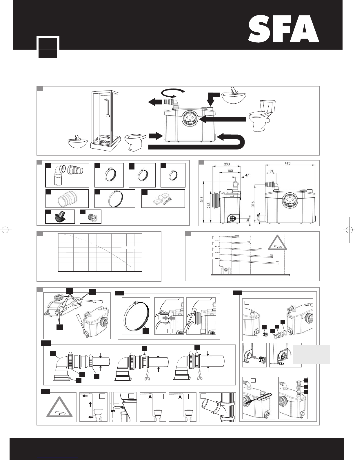
LISTE DES PIÈCES FOURNIES :
Voir fig. n° (cf fiche technique).
3
DIMENSIONS ET
ENCOMBREMENT :
Voir fig. n° (cf fiche technique).
4
APPLICATIONS ET DONNÉES
TECHNIQUES :
Cet appareil est un broyeur pompe
spécialement conçu pour évacuer les effluents
provenant dʼun WC et des appareils sanitaires
mentionnés à la fig. n° (Cf fiche technique).
Cet appareil est réservé à un usage
exclusivement domestique.
Vous trouvez les données techniques sur la
8
fig. n° (Cf fiche technique).
5
COURBE DE PERFORMANCES :
Voir fig. n° (cf fiche technique).
6
HAUTEUR ET LONGUEUR DE
L’ÉVACUATION :
Les combinaisons possibles entre hauteur et
longueur de lʼévacuation sont indiquées sur la
6
fig. n° (cf fiche technique).
7
INSTALLATION
ATTENTION : cet appareil est à raccorder à
une cuvette à sortie horizontale conforme à la
norme EN33 ou EN37.
Le broyeur doit se trouver dans la même pièce
que le WC et que les autres installations
sanitaires éventuellement raccordées. Lʼappareil
doit être dʼaccès aisé pour le contrôle et la
maintenance.
Il est fourni avec des dispositifs de fixation
lʼempêchant de tourner ou de bouger.
Afin dʼoptimiser les derniers développements
techniques en matière dʼacoustique inclus dans
cet appareil, il est important :
• dʼinstaller la cuve en évitant que celle-ci ne
touche une paroi de la pièce,
• de positionner la cuve sur un sol parfaitement
plat afin de ne pas contrarier le bon
fonctionnement des plots anti-vibratoires,
• de fixer correctement la tuyauterie
dʼévacuation en évitant des distances entre
les fixations supérieures à un mètre.
indication dont le non-respect
2
3
1
5
7a
RACCORDEMENT WC
Dans le cas où la fixation au sol se fait à
lʼaide de 2 plaquettes, fixer dʼabord celles-ci
sous la cuve avant de la positionner sur le sol.
• Enduire préalablement lʼextrémité de la
sortie WC avec du savon liquide,
• Enfiler le collier fourni sur la sortie cuvette,
• Aligner la manchette avec la sortie WC,
• Insérer la manchette de la sortie WC,
• Positionner le collier sur lʼextrémité de la
manchette puis le serrer avec un tournevis.
Une fois l'appareil mis en place, le fixer au
sol par l'intermédiaire des 2 vis fournies.
ATTENTION !!!
La chasse dʼeau (ainsi que tout appareil
sanitaire éventuellement raccordé au broyeur)
doit être parfaitement étanche. Une fuite
même légère provoque des démarrages
intempestifs du broyeur.
7b
RACCORDEMENTS D’APPAREILS
SANITAIRES
Se reporter à la fig. n° et fig. n°
7b27b1
(cf fiche technique) pour les éventuels
raccordements dʼappareils sanitaires.
ATTENTION : pour raccorder une douche,
veiller à surélever le fond du bac à douche
dʼau moins 18 cm par rapport au sol.
7c
RACCORDEMENT À L’ÉVACUATION
(cf. fiche technique fig. ).
SANIBROYEUR / SANIFLO / SANIBROY /
•
7c
SANITRIT / SANIPLUS UK / SANIPRO XR UK
SANITOP UK / SANI 1
orienter le coude de sortie dans le sens
désiré puis utiliser le tube plastique, sans le
plier, pour le raccordement à lʼévacuation. Si
nécessaire, utiliser le raccord 23/32 fourni.
• SANIBROYEUR PRO / SANIBROY PRO /
SANITOP / SANIPRO XR / SANIPLUS /
SANIBROYEUR TOP / SANIBROYEUR PLUS
SANI 2 / SANI 3 / SANILUX:
1-Votre appareil est équipé dʼun gros coude
caoutchouc blanc :
- Orienter lʼouverture du clapet anti-retour
du côté de la sortie prévue en le tournant
avec une pince ou en le dégageant et en
le remettant dans lʼextrémité de la sortie
caoutchouc du broyeur.
- Orienter le coude de sortie du même
côté, puis lʼenfiler sur le clapet anti-retour
et le serrer avec un collier .
A
B
2-Votre appareil est équipé dʼun coude
plastique et dʼun manchon souple :
- Insérer le manchon sur le coude. Le fixer
avec un collier .
B
- Orienter cet ensemble et lʼenfoncer dans
la durite noire (7c). Fixer la base du
coude avec un collier .
B
- Couper, si nécessaire, lʼextrémité du
manchon pour lʼadapter au tuyau dʼévacuation et utiliser un collier ou .
7d
CONSEILS TECHNIQUES POUR
L’ÉVACUATION
(cf. fiche technique fig. ).
7d
DC
• Éviter des "points bas" dans la conduite
dʼévacuation en la maintenant droite par des
colliers. Prévoir une pente de descente de
1% pour la partie dʼévacuation "horizontale",
• Évacuation verticale ascendante :
Prévoir la conduite montante à droite
de lʼappareil. Poursuivre lʼévacuation
gravitairement (1% de pente),
• Nous conseillons dʼinstaller une purge au
point bas pour faciliter la maintenance,
• Pour éviter le siphonnage :
- installer un casse-vide (genre Nicoll ou
similaires) au point haut, ou
- augmenter le Ø de la conduite horizontale,
• Lʼévacuation de lʼappareil doit être raccordée
à la chute des eaux vannes à lʼaide dʼun
raccord du commerce,
• Canalisations : les protéger par des isolants
appropriés contre le gel.
N.B. : Chaque coude placé sur lʼévacuation
de lʼappareil entraîne une diminution de la
capacité de relevage dʼenviron 50 cm par
coude.
Utiliser si possible des coudes à grand rayon
de courbure pour optimiser lʼécoulement.
• Il est recommandé d'installer un système
d'alarme externe Sanialarm SFA qui avertit
en cas de dysfonctionnement du broyeur.
Sur certains appareils, le point de perçage
est indiqué sur le couvercle.
7e
RACCORDEMENT ÉLECTRIQUE
N’effectuer le branchement
électrique qu’une fois les
raccordements définitifs terminés.
Lʼinstallation électrique doit être réalisée par
un professionnel qualifié en électrotechnique.
Lʼappareil doit être placé de façon telle que la
fiche de prise de courant soit accessible.
Le circuit dʼalimentation de lʼappareil doit être
relié à la terre (classe I) et protégé par un
disjoncteur différentiel haute sensibilité
/
(30mA) calibré à 10A minimum.
Le raccordement doit servir exclusivement à
lʼalimentation de lʼappareil.
Réglementation
Veillez à respecter les dispositions de la
norme en vigueur dans le pays dʼutilisation
(France : NF C 15-100) concernant les
volumes de protection dʼune salle de bains.
En cas de doute se mettre en rapport avec un
technicien qualifié.
Si le câble de cet appareil est endommagé,
il doit être remplacé par le fabricant ou son
Service Après Vente afin dʼéviter un danger.
8
NORME
• Cet appareil répond à la norme EN 12050-3
(Station de relevage à application limitée
pour effluents contenant des matières
fécales) et aux directives et normes
Européennes sur la sécurité électrique et la
compatibilité électromagnétique.
9
MISE EN SERVICE
Une fois les raccordements hydrauliques et
électriques effectués, actionner une fois la
chasse dʼeau, lʼappareil se met en marche
automatiquement et fonctionne entre 5 et
10 s selon la hauteur dʼévacuation. Au-delà de
20 s vérifier que la conduite dʼévacuation nʼest
pas pincée (freinage probable) ou que lʼévent
nʼest pas bouché.
Actionner plusieurs fois la chasse dʼeau.
Le passage cuvette doit être étanche. Vérifier
de même, si nécessaire, lʼétanchéité des
raccordements avec les autres appareils
sanitaires :lave-mains, douche, bidet, lavabo.
10
UTILISATION ET PRÉCAUTIONS
ATTENTION !!!
En cas d’absence prolongée (vacances),
il est impératif de couper l’alimentation
générale en eau de la maison.
Les toilettes équipées de votre nouvel
appareil sʼutilisent comme un WC classique et
demandent un entretien minimum. Le broyeur
démarre automatiquement dès quʼun certain
niveau dʼeau est atteint dans la cuve.
Toute application commerciale ou industrielle
est à proscrire.
Pour les évacuations horizontales :
• Respecter une pente de 1%,
• Éviter les points bas dans la canalisation.
La tuyauterie doit déboucher au-dessus du
niveau de la canalisation dʼévacuation
principale.
ATTENTION !!!
Ne sera prise en compte par la garantie
que l’évacuation de papiers hygiéniques,
matières fécales et eaux sanitaires.
Tout dommage causé à l’appareil par le
broyage de corps étrangers tels que coton,
tampons périodiques, serviettes
hygiéniques, lingettes, produits
alimentaires, préservatifs, cheveux, objets
en métal, en bois ou en plastique, ou le
pompage de liquides tels que solvants ou
huiles n'entrerait pas dans le cadre de la
garantie.
Cet appareil n’est pas destiné aux
personnes (y compris les enfants) dont
les capacités physiques, sensorielles ou
mentales sont limitées, ou auxquelles
l’expérience et les connaissances font
défaut, excepté si elles sont sous
surveillance et reçoivent les instructions
nécessaires pour utiliser l’appareil,
avec l’aide d’une personne responsable
de leur sécurité. Surveiller les enfants et
veiller à ce qu’ils ne jouent pas avec
l’appareil.
13
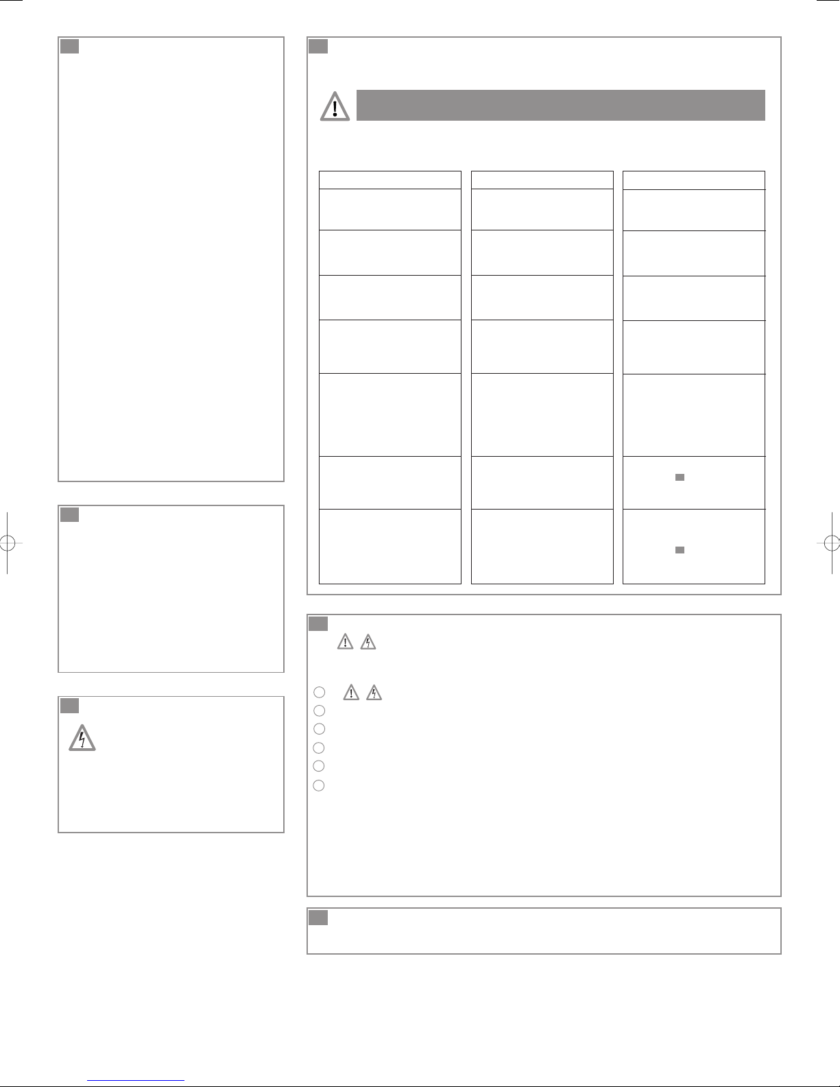
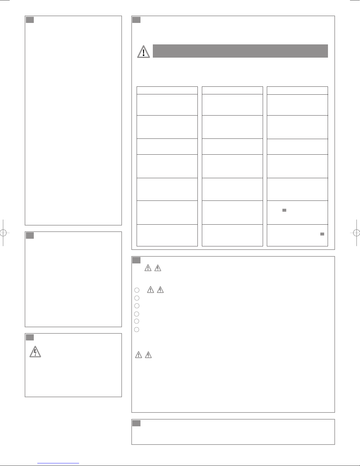
INTERVENTIONS ÉVENTUELLES
Certaines anomalies de fonctionnement des broyeurs ont des causes mineures.
Vous pouvez y remédier seul.
Pour aider au diagnostic et à la résolution d’anomalie, reportez-vous à la liste ci-après.
TOUTE OUVERTURE DE L’APPAREIL NE PEUT ÊTRE
EFFECTUÉE QUE PAR UN DÉPANNEUR AGRÉÉ.
DANS TOUS LES CAS, DÉBRANCHER
LA PRISE ÉLECTRIQUE DU BROYEUR
ANOMALIE CONSTATÉE
• L’appareil s’arrête
• L’appareil se remet en marche
par intermittence
• Le moteur tourne par à-coups
et l’eau descend lentement
dans la cuvette
• Le moteur tourne correctement mais
ne s’arrête plus ou tourne très
longtemps
• Le moteur ne démarre pas
• Le moteur tourne avec un bruit
de crécelle ou bourdonne
et ne tourne pas
• Retour d’eau trouble dans la douche
(appareils avec entrées latérales)
CAUSES PROBABLES
• L’appareil a fonctionné pendant
trop longtemps (coupure thermique
de sécurité)
• Problème électrique
• Les appareils sanitaires raccordés
fuient
• Le clapet anti-retour fuit
• L’évent du couvercle est bouché
• La hauteur ou longueur d’évacuation
est trop importante ou trop de
coudes (perte de charge)
• Le fond de pompe est bouché
• Appareil non branché
• Prise défectueuse
• Problème moteur ou système de
commande
• Moteur bloqué par un corps étranger
• Problème moteur ou système de
commande
• Douche installée trop bas
par rapport au broyeur
• Battants d’entrées latérales colmatés
• Faites appel à un dépanneur agréé
• Attendre le réenclenchement
• Contrôler l'installation en amont,
• Nettoyer ou changer le clapet
anti-retour
• Déboucher l’évent
• Revoir l’installation
• Sinon, consulter un dépanneur agréé
• Brancher l’appareil,
• Sinon, consulter un dépanneur agréé
• Enlever le corps étranger (voir
rubrique )
• Sinon, consulter un dépanneur agréé
• Revoir l’installation
• Nettoyer les battants
(voir rubrique )
• Sinon, consulter un dépanneur agréé
REMÈDES
14
14
11
NETTOYAGE / DÉTARTRAGE
Pour détartrer et nettoyer le broyeur et la cuvette,
utiliser régulièrement un détartrant adapté
comme le détartrant spécial SANIBROYEUR de
SFA, qui est conçu pour enlever le tartre tout en
respectant les organes internes de votre
appareil.
• Débrancher la prise électrique du broyeur,
• Mettre dans la cuvette une dose de détartrant,
• Laisser reposer plusieurs heures,
• Rebrancher la prise électrique du broyeur,
• Rincer en actionnant 2 fois la chasse dʼeau.
La fréquence de cette opération est en moyenne
dʼune fois tous les 3 mois mais doit être modulée
en fonction de la dureté de votre eau.
12
MAINTENANCE
AVANT TOUTE INTERVENTION
SUR L’APPAREIL, DÉBRANCHER
L’ALIMENTATION ÉLECTRIQUE.
Lʼappareil ne nécessite pas de maintenance
particulière.
Certains appareils SFA sont équipés de filtre
à charbon actif. Ce filtre doit être remplacé
tout les ans.
14
DÉMONTAGE
DÉBRANCHER LA PRISE DE COURANT AVANT
TOUTE INTERVENTION
COMMENT DÉGAGER LE BROYEUR DE LA CUVETTE
A
B
Fermer le robinet du réservoir. Enlever le maximum dʼeau du siphon de la cuvette,
C
Dégager le tuyau dʼévacuation du coude,
D
Dégager les raccordements aux appareils sanitaires,
E
Dévisser les 2 vis de fixation au sol,
F
Démonter le collier et séparer le broyeur de la cuvette en repoussant la manchette vers
Débrancher la prise de courant,
lʼappareil puis le tirer sur le côté.
CORPS ÉTRANGER
Débrancher la prise de courant
Enlever la manchette de lʼappareil pour bien dégager lʼorifice de lʼentrée et à lʼaide dʼun fil de fer ou
dʼun tournevis, ôter lʼobstacle qui empêche la rotation des couteaux.
Attention !
Ne jamais essayer de glisser la main pour dégager les lames (couteaux extrêmement coupants).
BATTANTS D’ENTRÉES LATÉRALES COLMATES
Enlever les manchons et avec un tournevis dégager éventuellement les battants caoutchoucs.
15
CONDITIONS DE GARANTIE
Lʼappareil est garanti deux ans à compter de sa date dʼachat sous réserve dʼune installation
et dʼune utilisation conformes à la présente notice.
UK
1
DESCRIPTION
The macerating system of this unit is installed in
a case specifically designed for horizontal outlet
spigots. This macerator is manufactured in
a factory which is quality certified to ISO
9001(2000) accredited by AFAQ.
Installed and used correctly, the unit will give
consistent and reliable service.
Please note the following warning signs:
""
Possible danger to personnel,
""
Warning of possible electrical hazard,
"ATTENTION"
This is a general warning that
failure to follow instructions could result
in poor functioning of the unit.
This equipment benefits from the latest
technological innovations concerning
soundproofing. To benefit fully from the
advantages provided by this new generation
of appliances, it is important to comply with the
installation instructions from onwards.
2
LIST OF ACCESSORIES
7
INCLUDED:
See fig. n° (cf. technical data sheet).
3
DIMENSIONS AND OVERALL
2
MEASUREMENTS:
See fig. n° (cf. technical data sheet).
4
TECHNICAL DATA:
3
This pump/macerator has been designed to
pump away the waste from a WC and the
sanitary appliances mentioned in fig n°
1
(cf. technical data sheet).
This unit is for domestic use only.
Installed and used correctly, this unit will give
consistent and reliable service.
You can find the technical data in fig n°
8
(cf. technical data sheet).
7a
WC CONNECTION
• First, put some silicon or liquid soap on the
WC spigot
• Fit the collar supplied on the pan spigot
• Pull the flexible sleeve over the pan spigot
• Position the metal hose clip over the edge of
the flexible sleeve, and tighten with a
screwdriver
• Once the appliance has been positioned, fix
it to the floor using the 2 screws supplied.
If using the two floor fixing lugs, secure them
to the floor before positioning the unit.
WARNING !!!
There should be no dripping of water from the
WC cistern or any other sanitary appliances.
If there is, this will cause the unit to activate
repeatedly as it pumps the water away.
7b
CONNECTION OF EXTRA SANITARY
APPLIANCES
See fig. n° et fig. n°
7b27b1
(cf. technical data sheet) for such connections
as may be required for sanitary appliances.
WARNING: Ensure when connecting a shower
to the unit that the underside of the shower tray
is raised by at least 12 cm from the floor.
7c
CONNECTION OF DISCHARGE
PIPEWORK
(cf. technical data sheet fig. ).
7c
Turn the discharge elbow bend in the desired
direction, then slide it onto the rubber hose
and fix it in place with the metal hose clip.
Then connect the hose to it using the 20-32mm
metal hose clip, making sure the hose is not
kinked.
N.B.: Any elbow on the discharge pipe of the
unit will create friction loss (roughly 50 cm per
elbow to be deducted from the vertical
pumping spec.)
Always use smooth bends (OR 2 X 45 degree
bends together) and not 90 degree elbows.
N.B.: Any elbow on the discharge pipe of the
unit will create friction loss (roughly 50 cm per
elbow to be deducted from the vertical pumping
spec.)
Always use smooth bends (OR 2 X 45 degree
bends together) and not 90 degree elbows.
We recommend the installation of an external
alarm system “SANIALARM” (fitted to the lid of
the unit), which warns the user in case of the
unit malfunction . This should be available from
your Saniflo supplier.
7e
CONNECTION TO THE ELECTRICAL
SUPPLY
The electrical installation should be
carried by a qualified person.
The unit should be connected to a fully earthed
electrical supply. All wiring must conform to
BS7671, 1992 requirements for electrical
installations. The unit requires a 220/240V
single phase AC 50 Hz supply (UK specification).
Do not connect the unit to a conventional plug
and socket. It must be wired into a fused,
unswitched, fixed wiring connector fitted with a
5 amp fuse. The wires in the mains lead are
coloured in accordance with the following
code:
Brown - Live
Blue - Neutral
Green/Yellow - Earth
Warning: Ensure the electricity is turned OFF
at the main switch board before wiring to
connector.
All work on cable, pressure chamber and
motor should only be carried out by a qualified
Saniflo servicing agent, as special tools are
required.
5
PERFORMANCE CURVE:
See fig. n° (cf. technical data sheet).
6
HEIGHT AND LENGTH
5
OF THE DISCHARGE PIPE:
The possible combinations of height and length
of the discharge pipe are shown in fig.
6
(cf. technical data sheet).
7
INSTALLATION
WARNING: The unit must be connected to WC
pan with a horizontal otlet spigot conforming to
EN33 or EN 37.
The unit should be accessible for possible
service.
It is supplied with fixing lugs to prevent it from
moving during use.
To optimise the latest technical developments
concerning soundproofing incorporated into this
unit, it is important to:
• position the WC pan so that it is not in contact
with a partition or wall of the room
• place the WC pan on a perfectly level surface
to ensure that the resilient mounts are fully
efficient
• fix the discharge pipe correctly, with distances
of not more than one metre between the
fastenings.
7d
TECHNICAL ADVICE FOR DISCHARGE
PIPEWORK
(cf. technical data sheet fig. ).
7d
• The discharge pipework should be run in
22mm copper or rigid plastic solvent weld
pipework.
• Horizontal pipe runs must have a minimum
fall of 1:100 (10 mm per metre) to the soil
stack,
• If a vertical lift is required, it must be made
before the horizontal run at the start of the
piperun,
• We would recommend that a drain-off point
is installed to allow the discharge pipework
to be drained down before any service work,
• If the discharge pipework runs to a level
considerably lower than the unit, the resultant
syphoning effect can suck out the water seal
in the unit. Fitting an air admittance valve
(BBA approved capable of withstanding 10 psi
pressure) at the high point of the pipe run
will overcome this problem,
• The discharge pipework must be connected
to the soil stack using an appropriate strap
on boss,
• Ensure all external pipework is adequately
lagged to avoid the possibility of freezing.
8
NORME
• This appliance conforms to EN 12050-3.
Lifting plant for wastewater containing faecal
matter for limited applications and the
European directives and standards
concerning electrical safety and
electromagnetic compatibility.
9
COMMISSIONING THE UNIT
Once electrical and plumbing connections have
been made, flush the WC once. The motor
should run from 5 to 10 seconds to clear the
waste (depending on the height of the pipe run).
If it runs for more than 20 seconds, check that
the pipework is clear, and that the discharge
hose is not kinked. Flush the WC checking that
all seals, and connections are watertight. Check
both the discharge pipework from the unit and
the other sanitary appliances connections.
10
USAGE AND WARNING
WARNING !!!
If away for a long periods (eg holidays) we
recommend that you turn off the water
supply to the WC served by the unit.
WCs connected to this unit can be used like
any normal toilet, and requires minimum
maintenance. The unit will operate
automatically as soon as the required level
of water enters the case.
This is a domestic unit.
For horizontal pipework:
• Minimum fall of 1:200 to the soil stack,
• Avoid any dips in the discharge pipe.
13
FAULT FINDING / REMEDIES
For the most past, any inconsistencies in the operation of the unit will be minor and easy
rectified. Please refer to the chart below.
IN ALL CASES, YOU MUST DISCONNECT THE MACERATOR FROM
THE POWER SUPPLY
If the problem cannot be easily remedied in this way, please call our Service organisation.
ALL WORK INVOLVING DISMANTLING OF THE APPLIANCE
MUST BE CARRIED OUT BY AN APPROVED REPAIR AGENT
SYMPTOMS
• The unit stops
PROBABLE CAUSES
• The unit has been running for too
long (thermal cut-out)
• Problem with electrics
• Ask an approved repair agent to
intervene
• Wait for reset
REMEDIES
WARNING !!!
Only the disposal of toilet paper, faecal
matter, and waste water will be under
guarantee. Any damage due to foreign
bodies such as cotton, condoms, sanitary
towels, wet wipes, food, hair, metal, wood
or plastic objects, will not be under
guarantee. Solvents, acids and other
chemicals can also cause damage to the
unit, and will invalidate the guarantee.
This device is not designed for
persons (including children) with
limited physical, sensory or mental
abilities, or those with minimal
experience and knowledge, unless
they are monitored and are given the
necessary instructions for using the
device, with the help of a person
responsible for their safety. Monitor
children and make sure they do not
play with the device.
11
CARE OF YOUR UNIT
In order to remove scale and clean the
macerator and the bowl, use a household
descalent (like SANIFLO Descaler).
• Disconnect the macerator power supply,
• Pour an amount of descalent in the pan
• leave it to stand for 1 or 2 hours,
• Re-connect the macerator power supply,
• Rinse by operating the flushing system twice.
Carry out the operation once every 3 months
on average, but the frequency may need to be
changed depending on the hardness of the
water.
12
MAINTENANCE
DISCONNECT THE ELECTRICAL
POWER SUPPLY, BEFORE
ATTEMPTING ANY WORK
ON THE UNIT.
No need of any particular maintenance.
Some SFA appliances are fitted with an active
carbon filter. This filter must be replaced every
year.
• The motor intermittently activates
• Motor is surging and water in the
WC pan goes down very slowly
• The motor operates normally, but
continues to run for a long time
• The motor does not activate
• The motor emits a rattling or
crunching sound, hums, but
does not run
• Cloudy water comes up into the
shower basin (units with side inlets)
14
REMOVAL
• The connected sanitary devices are
leaking
• The non-return valve is faulty
• The air dispenser is clogged up
• The length or height of the
installation is over the specification,
or there are too many bends/elbows
• The pump cover plate is occluded
• The electrical power supply is not
active
• The plug is defective
• The motor or the control system is
defective
• Foreign object into the box
• Problem with the motor or the
control system
• Shower installed too low as
compared with the macerator unit
• Hinged side inlet discs clogged up
• Check the installation upstream
• Clean or replace the non-return valve
• Clear the air dispenser
• Check the installation
• Otherwise, ask an approved repair
agent to intervene
• Restore the electrical supply
• Call a service engineer to check the
motor
• Otherwise, ask an approved repair
agent to intervene
• Remove the foreign body
(see section )
• Otherwise, ask an approved repair
agent to intervene
• Check the installation
• Clean the hinged discs
(see section )
• Otherwise, ask an approved repair
agent to intervene
14
14
DISCONNECT THE ELECTRICAL POWER SUPPLY
BEFORE ANY SERVICE
REMOVING THE UNIT FROM THE WC SUITE
A
B
Turn off the water feed to the WC cistern. Bail out as much water as possible from the cistern,
C
Remove discharge hose from elbow,
D
Disconnect any inlet pipes from the unit,
E
Unscrew the 2 fastening screws (to the floor) if fitted,
F
Remove the flexible connector off the WC pan spigot and slide the flexible connector off the WC
spigot and slide the unit out from behind the WC.
HINGED SIDE INLET VALVES CLOGGED
Remove the sleeves and use a screwdriver to free or clean the rubber flaps if necessary.
WARNING
Never try to put your hands inside the unit (extremely sharp blades).
Disconnect the electrical power supply,
15
GUARANTEE
2 years guarantee as from its date of purchase subject to correct installation and correct use.
D
1
ALLGEMEINES
Ihre Kleinhebeanlage ist zum Einbau hinter ein
Stand-WC mit horizontalem Ausgang (Euro-WC)
bestimmt. Die Herstellung dieser
Kleinhebeanlage in unserem ISO 9001 durch
AFAQ zertifizierten Werk, die einer ständigen,
strengen Qualitätskontrolle unterliegt.
Ihre Kleinhebeanlage bietet hohe Leistung,
Sicherheit und Zuverlässigkeit. Vorbehalt: bitte
beachten Sie alle nachfolgenden Einbau- und
Wartungshinweise.
Beachten Sie bitte besonders die Hinweise,
mit einem oder mehreren der folgenden
„Warnschilder“
""
Bei Missachtung: Gefahr körperlicher
Schäden,
""
Bei Missachtung: Gefahr durch
elektrischen Strom,
"ACHTUNG"
Hinweis, dessen
Nichtbeachtung Funktionsstörungen am Gerät
hervorrufen kann.
Dieses Gerät nutzt die neuesten technologischen
Innovationen im Bereich der Akustik. Damit Sie
in den Genuss des ganzen Komforts dieser
neuen Gerätegeneration kommen, ist es wichtig,
dass die Montagehinweise in Abschnitt
7
genau befolgt werden.
2
MITGELIEFERTES ZUBEHÖR:
vgl. Abb. (Technisches Merkblatt).
3
MASSE UND PLATZBEDARF:
vgl. Abb. (Technisches Merkblatt).
4
ANWENDUNGSBEREICHE UND
2
3
TECHNISCHE DATEN:
Dieses Gerät ist eine Kleinhebeanlage zum
Wegfördern von anfallendem Abwasser aus WC
und der in Abschnitt (echnisches Merkblatt)
1
aufgeführten Sanitäreinrichtungen.
Ihre Kleinhebeanlage ist zum Hausgebrauch
bestimmt.
Das Gerät profitiert von seiner Leistungsstärke,
hohem Sicherheits-standard und seiner
Zuverlässigkeit wird es gemäß den beiliegenden
Instruktionen installiert und gewartet.
Entnehmen Sie die technischen Daten aus
8
Abb. (echnisches Merkblatt).
5
LEISTUNGSKURVE:
vgl. Abb. (Technisches Merkblatt).
6
HÖHE UND LÄNGE DER
5
ABLEITUNG:
Die möglichen Kombinationen zwischen Höhe
und Länge der Ableitung sind in Abb.
6
(Technisches Merkblatt) angegeben.
7
INSTALLATION
ACHTUNG: dieses Gerät ist zum Anschluss
an ein Euro-WC mit horizontalem Abgang
vorgesehen.
Die Kleinhebeanlage muss sich im selben
Raum befinden wie die angeschlossene
Toilette und sämtliche angeschlossenen
Sanitäreinheiten.
Die Einheit muss leicht zugänglich für
eventuelle Wartungs- oder Kontrollarbeiten sein.
Im Lieferumfang befinden sich die
Befestigungsvorrichtungen, die verhindern, dass
sich die Anlage während des Betriebes dreht
oder bewegt.
Zur Optimierung der jüngsten technischen
Entwicklungen im Bereich der Akustik, die für
dieses Gerät genutzt wurden, ist es wichtig:
• das WC so zu installieren, dass es keine
Wand des Raums berührt,
• das WC auf einen vollkommen ebenen Boden
zu stellen, damit die schwingungsdämpfenden
Vorrichtungen einwandfrei funktionieren können,
• das Abgangsrohr korrekt zu befestigen und
darauf zu achten, dass der Abstand zwischen
den Befestigungen nicht größer ist als ein
Meter.
7a
ANSCHLUSS AN DAS WC
• Den Toilettenabgang mit etwas Spülmittel
einstreichen,
• Die mitgelieferte Schelle auf den
WC-Abgang stülpen,
• Die Gummimanschette über den
Abgangsbogen ziehen.,
• Schelle über die Gummimanschette
anbringen und mit einem Schraubenzieher
auf dem WC-Abgang befestigen.
Nachdem das Gerät installiert ist, wird es mit
den 2 mitgelieferten Schrauben am Boden
befestigt.
Falls die Befestigung am Boden mit 2 Platten
erfolgen soll, müssen diese zuerst unter dem
WC befestigt werden, bevor dieses auf dem
Boden positioniert wird.
ACHTUNG !!!
Wasserspülung und Armaturen müssen dicht
sein, das Gerät kann ansonsten automatisch
anlaufen.
7b
ANSCHLUSS WEITERER
SANITÄREINHEITEN
Die Anschlussweise eventueller weiterer
Sanitäreinheiten entnehmen Sie Abb. n°
und fig. n° (Technisches Merkblatt).
7b2
7b1
ACHTUNG : Die Zulaufleitung muß gemäß
DIN 12050-3 eine Höhe von 180 mm haben
um einen Rückstau zu verhindern.
7c
ANSCHLUSS AN DIE ABGANGSLEITUNG
(Technisches Merkblatt Abb. ).
7c
• SANIBROYEUR / SANIFLO / SANIBROY /
SANITRIT/ SANI 1:
Den Abgangsbogen in die gewünschte
Richtung drehen und dann mit dem
Kunststoffrohr – nicht knicken ! – den
Anschluss an die Ableitung herstellen.
Falls nötig den mitgelieferten Adapter 23/32
verwenden.
• SANIBROYEUR PRO / SANIBROY PRO /
SANITOP / SANIPRO XR / SANIPLUS /
SANIBROYEUR TOP / SANIBROYEUR PLUS/
SANI 2 / SANI 3 / SANILUX:
1-Ihr Gerät ist mit einem dicken
Gummikniestück ausgestattet:
- Die Öffnung des Rückschlagventils durch
Drehen mit einer Zange oder durch
Ausrücken und Wiedereinsetzen an der
anderen Seite des Gummiaustritts des
Zerkleinerers zum vorgesehenen Austritt
ausrichten.
2-Ihr Gerät ist mit einem Kunststoffkniestück
und einem weichen Überschiebestück
ausgestattet:
- Das Überschiebestück über das Kniestück
schieben. Es mit einer Schelle
B
befestigen.
- Die Einheit richtig ausrichten und in den
schwarzen Schlauch drücken (7c). Den
Fuß des Kniestücks mit einer Schelle
B
befestigen.
- Bei Bedarf das Ende des Überschiebestücks abschneiden und an das
Abflussrohr anpassen. Eine Schelle
D
oder benutzen.
C
7d
TIPPS FÜR DIE ABGANGSLEITUNG
(vgl. technisches Merkblatt Abb. ).
7d
• Tiefpunkte in der Abgangsleitung vermeiden.
Es können sich Ablagerungen bilden, was zu
Leistungsverringerungen der
Kleinhebeanlage führen kann. “Horizontale”
Leitungen mit 1% Gefälle verlegen,
• Die Steigleitung sollte rechts vom Gerät
nach oben gehen. Anschließend mit 1%
Gefälle zur Kanalisation weiterleiten,
• Wir empfehlen, am tiefsten Punkt des
Steigrohres ein Ablassventil anzubringen,
damit bei eventuellen Wartungsarbeiten im
Rohr stehendes Wasser abgelassen werden
kann,
• Um ein Leersaugen des Siphons zu
vermeiden:
- eine Lüftungsleitung vorsehen
- den Durchmesser der horizontalen
Ableitung vergrößern,
• Die Abgangsleitung des Geräts an das
Fallrohr erfolgt über eine handelsübliche
Einleitung,
• Frostgefährdete Leitungen mit geeignetem
Isoliermaterial schützen.
ACHTUNG: jeder in der Ableitung eingesetzte
Bogen “frisst“ ca. 50cm Steighöhe oder einen
Meter Pumpleistung auf Distanz.
Möglichst Bögen mit großem Biegungsradius
verwenden, um den Ablauf zu optimieren.
Es wird empfohlen, ein externes Alarmsystem
SANIALARM SFA zu installieren, das bei einer
Störung des Zerkleinerers Alarm schlägt. Bei
bestimmten Geräten ist der Bohrpunkt auf
dem Deckel angegeben.
7e
ELEKTRONANSCHLUSS:
Die Elektroinstallation muss durch
einen Fachmann erfolgen. Die
Steckdose ist vorschriftsmäßig
anzubringen
Die Elektroinstallation hat von einem
autorisierten Fachmann zu erfolgen.
Die Steckdose so installiert sein, dass diese
frei zugänglich ist.
Die Versorgungsleitung des Geräts muss
geerdet sein (Klasse I) und durch eine
hochempfindliche Fehlerstromshutzschalter
(30 mA) geschützt sein. Die Schutzvorrichtung
muss auf 10 A (minimum) kalibriert sein.
Im Zweifelsfall durch einen qualifizierten
Elektriker überprüfen lassen.
Ein beschädigtes Kabel dieses Geräts
muss durch den Hersteller oder seinen
Kundendienst überprüft werden, um jede
Gefährdung auszuschließen.
Bestimmungen:
Bitte beachten Sie die Einhaltung der
Errichtungsnormen wie z.B. DIN VDE 0100,
Teil 701 (Feucht- und Nassräume,
Fehlerstromshutzschalter usw.).
Sollte das Netzkabel beschädigt sein,
muss es vom Hersteller oder von einem
autorisierten Servicepartner unverzüglich
ersetzt werden, da dies eine Sicherheitsgefahr
darstellt.
Vor jeder Reparatur an der Einheit Stecker
ziehen !
8
NORMEN
• Dieses Gerät entspricht folgender Norm:
EN12050-3 Kleinhebeanlagen zur
begrenzten Verwendung für
fäkalienbelastetes Abwasser und den
europäischen Richtlinien und Normen über
die Sicherheit von elektrischen Anlagen und
elektromagnetische Kompatibilität.
9
FUNKTIONSTEST
Wenn die Anschlüsse fertig sind, einige Blatt
Toilettenpapier einwerfen. Wasserspülung
betätigen. Das SFA-Gerät arbeitet automatisch
und die Entsorgung dauert von 5 bis zu 10
Sekunden, je nach Förderhöhe. Falls länger,
Förderhöhe prüfen.
Sanitäreinheiten laufen lassen und die Dichtheit
der Abwasserleitungen prüfen.
10
NUTZUNG UND
VORSICHTSMASSREGELN
WICHTIGER HINWEIS !!!
Bei längerer Abwesenheit (z.B.
Urlaubsreise), wird dringend empfohlen,
die Wasserzuleitungen abzustellen.
Eine mit einer Kleinhebeanlage installierte
Toilette funktioniert wie ein normales WC.
Die Förderfunktion beginnt automatisch, wenn
der Wasserspiegel im Gerätebehälter ansteigt
und endet automatisch.
Achtung : gewerblicher Betrieb wird aus
Zulassungsgründen nicht empfohlen.
Bei horizontalem Fördern :
- Ein 1%iges Gefälle einhalten
- Tiefpunkte in der Ableitung sind zu
vermeiden
Die Steigleitung muss oberhalb der
Hauptabwasserleitung in das Fallrohr
eingeleitet werden, dies ist auch dann gültig,
wenn mehrere Rückschlagklappen eingebaut
wurden.
ACHTUNG!!!
Wie jede Toilette dient Ihre
Kleinhebeanlage nur zur Entsorgung von
Fäkalien, Urin und Toilettenpapier in das
Abwassernetz. Schäden durch Fremdstoffe
(wie z.B. Haare, Hygieneartikel,
Lösungsmittel, Öle, Küchenbzw.
Essenreste, Gegenstände aus Metall, Holz
oder Plastik, Faserstoffe usw.) fallen nicht
unter die Garantieleistung.
Dieses Gerät ist nicht dafür bestimmt,
durch Personen (einschließlich Kinder) mit
eingeschränkten physischen, sensorischen
oder geistigen Fähigkeiten oder mangels
Erfahrungen und/oder mangels Wissen
benutzt zu werden, es sei denn, sie werden
durch eine für ihre Sicherheit verantwortliche
Person beaufsichtigt oder erhielten von ihr
eine Anweisung, wie das Gerät zu benutzen
ist. Kinder sollten beaufsichtigt werden, um
sicherzustellen, dass sie nicht mit dem
Gerät spielen.
11
REINIGUNGSMASSNAHMEN
Zum Reinigen der Kleinhebeanlage
und des WC bitte regelmäßig handelsübliche
WC-Reinigungsmittel verwenden.
• Netzstecker ziehen,
• eine Entkalkungsmitteldosis in der Schüssel zu
schütten,
• Mehrere Stunden einwirken lassen,
• den Netzstecker wieder einstecken,
• zum Durchspülen 2-mal die Wasserspülung
betätigen.
Diese Reinigung sollte durchschnittlich alle
3 Monate durchgeführt werden, ist aber an die
Härte Ihres Wassers anzupassen.
12
INTERVENTIONEN
AN DER KLEINHEBEANLAGE
VOR JEDEM ARBEITEN AN DER
KLEINHEBEANLAGE IST DIE
STROMZUFUHR ZU
UNTERBRECHEN.
Ihre Kleinhebeanlage benötigt keine besonderen
Wartungsmaßnahmen.
Einige SFA-Geräte sind mit einem
Aktivkohlefilter ausgerüstet. Dieser Filter
muss jedes Jahr ausgewechselt werden.
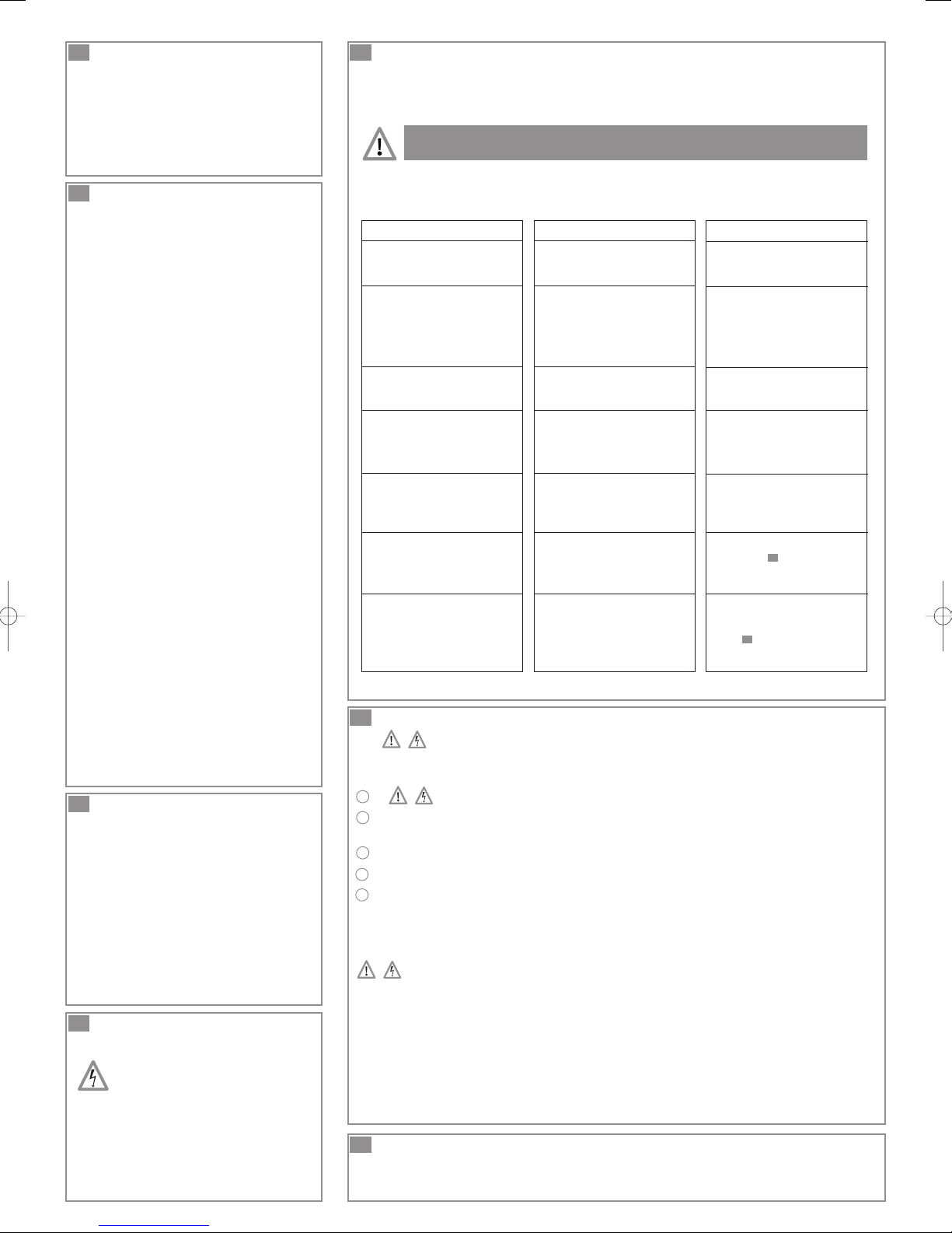
13
FEHLFUNKTIONEN UND DEREN BEHEBUNG
Einige Betriebsstörungen haben kleine Ursachen, Sie können diese selbst beheben.
Anhand untenstehender Störfall-Liste können Sie die Ursachen von Fehlfunktionen
selbst ermitteln und beseitigen.
IN JEDEM FALL MUSS DER NETZSTECKER DER
KLEINHEBEANLAGE AUSGESTECKT WERDEN!
FÜR JEDES WEITERE PROBLEM, DAS EIN ÖFFNEN DES
GERÄTS ERFORDERT, WENDEN SIE SICH AN EINE
AUTORISIERTE SERVICE-STELLE.
PANNEN
• Das Gerät bleibt stehen
• Gerät läuft von Zeit zu Zeit an
• Der Motor dreht sich ruckweise und
Wasser läuft langsam in das Becken
• Motor läuft, aber arbeitet sehr lange
oder schaltet gar nicht ab
• Motor startet nicht
• Motor macht laute Geräusche oder
brummt aber läuft nicht
• Schmutzwasser wird in die Dusche
abgedrängt (Geräte mit seitlichem
Zulauf)
• Das Gerät war zu lange in Betrieb
(hitzebedingte Stromunterbrechung)
• Elektrisches Problem
• WC-Spülung oder eine angeschlossene
Sanitäreinheit sind nicht dicht
• Rückschlagklappe ist undicht
• Belüfterklappe ist verstopft
• Förderhöhe oder -weite zu hoch
oder zu weit gewählt, oder zu viele
Winkel eingebaut
• Pumpenboden ist verstopft
• Netzspannung fehlt
• Motor überlastet,
Überhitzungsschutz ausgelöst
• Motor oder Steuerungssystem defekt
• Fremdkörper im Gerät
• Motor oder Steuerungssystem
defekt
• Die Dusche ist im Verhältnis zum
Kleinhebegerät zu niedrig installiert
• Seitliche Eingangsklappen verstopft
URSACHEN
• Kundendienst benachrichtigen
• Das erneute Einschalten abwarten
• Funktion und Dichtheit aller
angeschlossenen Sanitärgeräte
prüfen und gegebenenfalls
auswechseln
• Rückschlagklappe reinigen oder
Austauschen
• Belüfterklappe reinigen
• Die Abgangsleitung nochmals
überdenken
• Andernfalls, einen zugelassenen
Mechaniker zu befragen
• Gerät einstecken
• Andernfalls, einen zugelassenen
Mechaniker zu befragen
• Fremdkörper entfernen
(siehe Punkt )
• Andernfalls, einen zugelassenen
Mechaniker zu befragen
• Die Abgangsleitung nochmals
überdenken
• Eingangsklappen reinigen (siehe
Punkt )
• Andernfalls, einen zugelassenen
Mechaniker zu befragen
Dieses Gerät darf ausschließlich von einem autorisierten Kundendiensttechniker geöffnet werden.
14
DEMONTAGE
BEHEBUNG
14
14
VOR JEDEM ARBEITEN AN DEM GERÄT DEN
NETZSTECKER ZIEHEN.
ENTFERNEN SIE DAS GERÄT VON DEN WC
A
B
Wasserzuläufe und / oder Haupthahn schliessen. Förderrohr leer laufen lassen und
Netzstecker ziehen,
abnehmen. Wasser aus dem WC abpumpen.,
C
Waschtischanschluss (falls benutzt) abtrennen,
D
Schelle an der WC Manschette lösen und Verbindung zwischen WC und das Gerät trennen,
E
Bodenbefestigung lösen und die Anlage seitlich hinter dem WC herausziehen,
FREMDKÖRPER
Netzstecker ziehen,
Die Muffe vom Gerät abnehmen, um die Zulauföffnung freizulegen. Mit einem Draht oder
Schraubenzieher den Gegenstand entfernen, der die Rotation behindert.
Achtung!
Versuchen Sie niemals, die Messer mit der Hand zu reinigen! (Die Schneiden sind extrem scharf!).
SEITLICHE EINGANGSKLAPPEN VERSTOPFT
Muffen entfernen und die Gummi-Klappen eventuell mit einem Schraubenzieher vom Schmutz befreien.
15
GARANTIEBESTIMMUNGEN
Wir bieten für den Gerät eine zweijährige Garantie ab Kaufdatum bei zweckentsprechender
Nutzung und fachgerechtem Einbau.
I
1
AVVERTENZE
Il sistema di triturazione del vostro apparecchio è
installato in una vaschetta appositamente studiata
per le tazze ad uscita orizzontale. Il trituratore è
un apparecchio sviluppato a regola d'arte e
sottoposto ad un controllo di qualità permanente
in una fabbrica certificata ISO 9001 versione
2000 dallʼAFAQ. Questo apparecchio è destinato
ad un uso sanitario. E' dotato di un alto livello di
sicurezza e di affidabilità se tutte le regole di
installazione e di funzionamento descritte in
questo libretto sono scrupolosamente rispettate.
In particolare le indicazioni riguardanti:
""
avvertenze che se non rispettate
potrebbero causare rischi alla persona,
""
avvertenze riguardanti la presenza di
rischi dʼorigine elettrica.
"
ATTENZIONE
"
indicazione che se non
rispettate, potrebbero condizionare il
funzionamento dellʼapparecchio.
Il presente apparecchio è dotato delle ultime
innovazioni tecnologiche in campo di acustica.
Per usufruire pienamente del comfort di questa
nuova generazione di apparecchi, seguire
scrupolosamente i consigli di montaggio descritti
nella sezione
2
Vedi fig. n° (Cfr scheda tecnica).
3
4
7
.
LISTA DEI PEZZI A CORREDO
2
DIMENSIONI E INGOMBRO
Vedi fig. n° (Cfr scheda tecnica).
3
CARATTERISTICHE TECNICHE
Questo apparecchio è una pompa trituratrice
destinata allʼevacuazione delle feci, della carta
igienica e dagli apparecchi sanitari menzionati
nella fig. (Cfr scheda tecnica).
1
Questo apparecchio è riservato ad un uso
esclusivamente domestico.
Eʼ dotato di un alto livello di sicurezza e di
affidabilità se tutte le regole di installazione e di
funzionamento descritte in questo libretto sono
scrupolosamente rispettate.
Per i dati tecnici vedi fig.
8
(Cfr scheda tecnica).
5
PRESTAZIONI
Vedi fig. n° (Cfr scheda tecnica).
6
ALTEZZA E LUNGHEZZA
4
DELL’EVACUAZIONE
Le combinazioni possibili tra altezza e lunghezza
dell'evacuazione sono descritte nella fig. n°
6
(Cfr scheda tecnica).
7
INSTALLAZIONE
ATTENZIONE:
in tutti i casi il trituratore deve
essere raccordato ad un WC in ceramica
con scarico orizzontale conforme alla normativa
EN 33 o EN 37
Il trituratore deve trovarsi nel vano previsto per il
WC e per le altre installazioni sanitarie
eventualmente collegate. Lʼapparecchio deve
essere installato in modo da garantire un agile
accesso al controllo e alla manutenzione
Esso viene fornito assieme ai dispositivi di fissaggio
che ne impediscono la rotazione o di spostarsi.
Per ottimizzare gli ultimi sviluppi tecnologici in
campo di acustica inclusi nel presente apparecchio,
è imperativo:
- installare la vaschetta in modo da evitare che sia
in contatto con una parete del vano
- posizionare la vaschetta su un suolo perfettamente
piatto in modo da non contrariare il corretto
funzionamento dei piedini antivibrazioni
- fissare correttamente i tubi di evacuazione evitando
distanze tra fissazioni superiori ad un metro.
7a
RACCORDO WC
Per prima cosa, cospargere l'estremità
•
dell'uscita WC con sapone liquido.
• Infilare il collare fornito sull'uscita della tazza
• Allineare il manicotto con l'uscita WC,
• Inserire il manicotto dell'uscita WC
• Utilizzare un cacciavite per serrare il
manicotto allʼuscita del wc
Dopo aver posizionato l'apparecchio, fissarlo
al suolo per mezzo delle 2 viti fornite.
Se il fissaggio va realizzato per mezzo di
2 piastrine, fissare queste ultime sotto la tazza
prima di posizionarla sul suolo.
ATTENZIONE !!!
Il vaso (come pure qualsiasi altro apparecchio
sanitario eventualmente raccordato al trituratore)
deve essere perfettamente stagna. Una perdita
del vaso, anche se minima provoca
funzionamenti indesiderati dellʼapparecchio.
7b
RACCORDO DI APPARECCHI
SANITARI
Vedi fig. n° (Cfr scheda tecnica) per gli
7b
eventuali raccordi di apparecchi sanitari.
ATTENZIONE : per lʼinstallazione di una doccia
la piletta deve essere a 18 cm dal pavimento.
7c
ALLACCIAMENTO AL TUBO DI SCARICO
(Cfr scheda tecnica fig. n° ).
7c
• SANIBROYEUR / SANIFLO / SANIBROY /
SANITRIT / SANI 1:
orientare il gomito di uscita nel senso voluto,
poi utilizzare il tubo di plastica, senza
piegarlo, per raccordarlo all'evacuazione. Se
necessario, utilizzare il raccordo 23/32 fornito.
• SANIBROYEUR PRO / SANIBROY PRO /
SANITOP / SANIPRO XR / SANIPLUS /
SANIBROYEUR TOP / SANIBROYEUR PLUS /
SANI 2 / SANI 3 / SANILUX:
1-Il vostro apparecchio è munito di un grosso
gomito bianco di gomma:
- Orientare l'apertura della valvola anti-ritorno
dal lato dell'uscita prevista ruotandola con
una pinza o estraendola e rimettendola
nell'estremità dell'uscita in gomma del
trituratore
- Orientare il gomito d'uscita, quindi infilarlo
sul tubo in gomma (pezzo ) e serrarlo
con un cacciavite (pezzo ),
A
B
2. Il vostro apparecchio è munito di un gomito
di plastica e di un manicotto morbido:
- Inserire il manicotto nel gomito. Fissarlo
con un collare .
B
- Orientare l'insieme e infilarlo nella tubo
nero (7c). Fissare la base del gomito con
un collare .
B
- Tagliare, se occorre, l'estremità del manicotto per adattarla al tubo d'evacuazione
ed usare un collare o .
7d
CONSIGLI TECNICI
(cfr. scheda tecnica fig. ).
DC
7d
• Evitare “punti bassi” nel percorso dei tubi
prevedendo una pendenza dellʼ1% per la
parte orizzontale del percorso.
• Evacuazione verticale ascendente :
Prevedere il condotto in salita al traverso
dell'apparecchio. Continuare l'evacuazione
nel tratto in discesa (1% di pendenza).
• Si consiglia d'installare uno spurgo nel punto
basso al fine di facilitare le operazioni di
manutenzione.
• Per evitare il travaso attraverso il sifone:
- installare un rompivuoto (genere Nicoll o
simili) nel punto alto, oppure
- aumentare il Ø del condotto orizzontale.
• Lʼevacuazione dellʼapparecchio va raccordata
alle acque usate per mezzo di un raccordo
disponibile sul commercio.
• Proteggere i tubi dal gelo con lʼopportuno
materiale isolante
N.B.: per una corretta installazione del
trituratore, sul tratto verticale non è possibile
fare curve sul tubo di scarico.
La sola curva deve essere fatta in prossimità
dell'apparecchio in modo da raggiungere in
modo lineare il punto più alto.
Se possibile, utilizzare gomiti a largo raggio di
curvatura in modo da ottimizzare lo scorrimento
Si raccomanda d'installare un sistema
d'allarme esterno. Sanialarm SFA che avverte
in caso di guasto del trituratore. Su alcuni
apparecchi, il punto di perforazione è
segnalato sul coperchio.
7e
COLLEGAMENTO ELETTRICO
Effettuare il collegamento alla rete
elettrica solo dopo aver terminato
l’allacciamento idraulico
Lʼimpianto elettrico deve essere realizzato da
un professionista qualificato in elettrotecnica.
L'apparecchio va collocato in modo tale che la
spina della presa di corrente sia accessibile.
Il circuito d'alimentazione dell'apparecchio va
collegato a terra (Classe I) e protetto da un
disgiuntore differenziale ad alta sensibilità
(30 mA) calibrato a 10 A minimo.
Il collegamento deve servire esclusivamente
all'alimentazione dell'apparecchio. In caso di
dubbi, fare controllare da un elettricista
qualificato.
Normativa
Si raccomanda di rispettare le disposizioni
della norma in vigore nel paese di utilizzazione
riguardo ai volumi di protezione di una sala da
bagno. In caso di dubbio, prendere contatto
con un tecnico qualificato.
Se il cavo di questo apparecchio è danneggiato,
deve essere sostituito dal fabbricante o dal
suo Servizio Assistenza per evitare pericoli.
8
NORMA
• Il presente apparecchio è conforme alla norma
EN 12050-3 (Stazione di sollevamento con
applicazione a scarichi contenenti materie
fecali).
9
MESSA IN FUNZIONE
Una volta terminate tutte le operazioni di
installazione elettrica ed idraulica azionare
lo scarico wc, lʼapparecchio SFA si metterà in
funzione per un periodo di tempo variabile
tra i 5 e i 10 secondi a seconda dellʼaltezza
dello scarico in verticale. Se il periodo del
funzionamento supera i 20 secondi verificare
che il tubo di scarico non sia piegato o che
lo sfiato dellʼapparecchio non sia bloccato.
Eseguire questa operazione di scarico più
volte verificando che lʼallacciamento al wc
non abbia perdite. Verificare ugualmente,
se necessario, la tenuta stagna dei raccordi
con gli altri apparecchi sanitari: lavandino,
doccia, bidet.
10
UTILIZZO E PRECAUZIONI
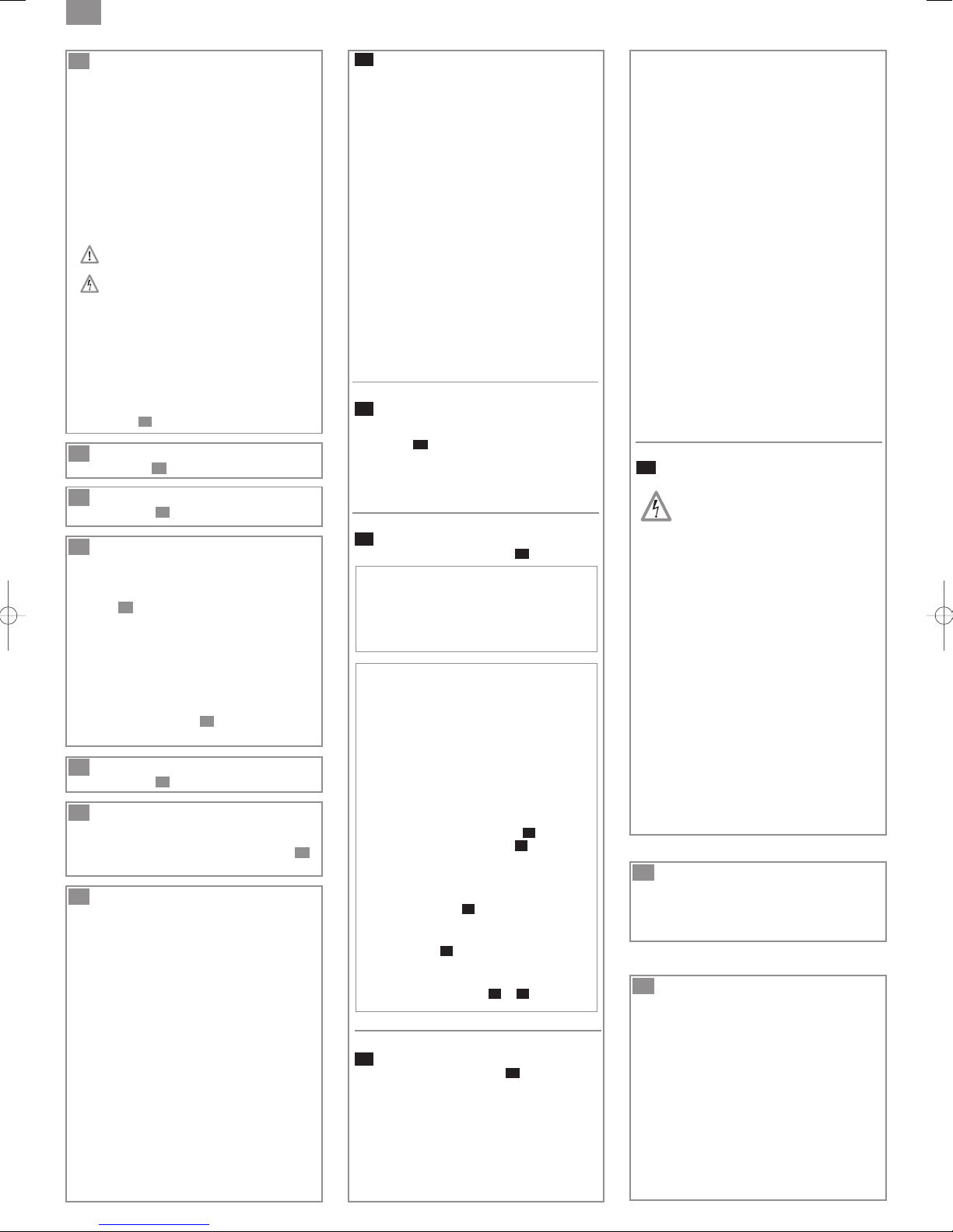
13
EVENTUALI INTERVENTI
ATTENZIONE !!!
In caso di assenza prolungata (vacanze),
è obbligatorio interrompere l'alimentazione
generale d'acqua dell'abitazione.
Le toilette dotate del vostro nuovo
apparecchio vanno utilizzate come un WC
classico e richiedono una manutenzione
minima. Il trituratore partirà automaticamente
quando il livello dellʼacqua ricevuta sarà
sufficiente a farlo scaricare.
Non utilizzare l'apparecchio per applicazioni
commerciali o industriali.
Per le evacuazioni orizzontali:
• Rispettare una pendenza dell' 1%,
• Evitare i punti bassi nella canalizzazione,
I tubi devono sboccare sopra il livello della
canalizzazione di evacuazione principale.
ATTENZIONE !!!
Ai fini della garanzia verrà presa in conto
solo l'evacuazione di carta igienica,
materie fecali e acque sanitarie.
Qualsiasi danno dovuto alla frantumazione
di corpi estranei quali cotone, tamponi
assorbenti, preservativi, capelli, salviettine,
prodotti alimentari, oggetti di metallo,
legno o plastica o dal pompaggio di liquidi
quali solventi o oli fa decadere la garanzia.
Questo apparecchio non è destinato
alle persone (ivi compresi i bambini) le cui
capacità fisiche, sensoriali o mentali sono
limitate, o alle quali fanno difetto
esperienza e conoscenze, eccetto se sorvegliate e qualora ricevano le istruzioni
necessarie per utilizzare l'apparecchio,
con l'aiuto di una persona responsabile
della loro sicurezza. Sorvegliare i
bambini e badare che non giochino con
l'apparecchio.
11
PULIZIA, RIMOZIONE DEL
CALCARE
Per pulire e disincrostare il trituratore ed il WC in
ceramica utilizzare regolarmente un prodotto
adeguato per togliere le incrostazioni. SFA ha
ideato e progettato un liquido anticalcare
apposito, in grado di non rovinare le prestazioni
del vostro trituratore.
• scollegare la presa elettrica del trituratore,
• inserire nel wc una quantità di prodotto
• Lasciare riposare il tutto per qualche ora
• Ricollegare la presa elettrica del trituratore
• Sciacquare azionando 2 volte lo sciacquone.
Tale operazione va eseguita in media una volta
ogni tre mesi. Da modularsi a seconda della
durezza della vostra acqua.
12
MANUTENZIONE
PRIMA DI INTERVENIRE
SULL'APPARECCHIO,
SCOLLEGARE L'ALIMENTAZIONE
ELETTRICA.
L'apparecchio non richiede una manutenizone
particolare.
Alcuni apparecchi SFA sono dotati di filtro
a carbone attivo. Questo filtro deve essere
sostituito ogni anno.
Alcune anomalie di funzionamento dei trituratore sono dovute a cause secondarie, per aiutarvi alla
diagnosi ed alla risoluzione di queste anomalie, fate riferimento alla lista seguente.
IN TUTTI I CASI SCOLLEGARE LA PRESA ELETTRICA DEL
TRITURATORE
Per qualsiasi altro problema che richieda l'apertura dell’apparecchio, contattare il servizio
clienti o un riparatore autorizzato.
L'APERTURA DELL'APPARECCHIO PUÒ ESSERE ESEGUITA
SOLO DA UN RIPARATORE QUALIFICATO
ANOMALIE CONSTATATE,
• l'apparecchio si ferma
• L’apparecchio si rimette in moto
senza interruzione
• Il motore gira irregolarmente e
l'acqua scende lentamente nel vaso
• Il motore gira correttamente ma non
si arresta mai o gira troppo a lungo
• Il motore non parte
• Il motore gira generando un
crepitante rumore ronza ma non
pompa
• Ritorno di acque usate nella doccia
(apparecchi con entrate laterali)
14
SMONTAGGIO
PROBABILI CAUSE,
• L’apparecchio è rimasto in funzione
troppo a lungo (interruzione termica
di sicurezza)
• Problema elettrico
• Gli apparecchi sanitari collegati
perdono
• La valvola antiritorno perde
• Lo sfiatatoio del coperchio è
otturato
• L’altezza o la lunghezza dello scarico
è eccessiva
• Il fondo pompa è ostruito
• Apparecchio mal collegato
• Presa di corrente difettosa
• Problema di motore o sistema di
comando
• Motore bloccato da un corpo
estraneo
• Problema motore o sistema di
comando
• Doccia installata troppo in basso
rispetto al trituratore
• Otturatori di entrate laterali
ostruiti
• Rivolgersi ad un riparatore
qualificato.
• Aspettare il ripristino
• Controllare l’installzione a monte,
• Pulire o sostituire la valvola
antiritorno
• Liberare lo sfiatatoio
• Modificare l’installazione
• Se necessario, contattare un
riparatore autorizzato
• Collegare l’apparecchio correttamente
• Se necessario, contattare un
riparatore autorizzato
•
Eliminare il corpo estraneo (vedi
rubrica )
• Se necessario, contattare un
riparatore autorizzato
• Modificare l’installazione
• Pulire gli otturatori (vedi rubrica )
• Se necessario, contattare un
riparatore autorizzato
RIMEDI
14
14
SCOLLEGARE LA PRESA DI CORRENTE PRIMA DI
EFFETTUARE QUALSIASI INTERVENTO
COME SCOLLEGARE IL TRITURATORE DAL VASO
A
B
Chiudere il rubinetto di carico acqua. Eliminare la maggior parte di acqua dal sifone del WC.
C
Liberare il tubo di evacuazione,
Liberare i raccordi degli apparecchi sanitari
D
E
Svitare le 2 viti dei dispositivi di fissaggio,
F
Smontare il manicotto e separare quindi il trituratore dal vostro WC facendo leva sulle estremità
Scollegare assolutamente la presa di corrente,
del manicotto di collegamento.
CORPO ESTRANEO
Scollegare assolutamente la presa di corrente,
Servendosi di un filo di ferro o di un cacciavite, togliere il manicotto dell'apparecchio per liberare
bene l'orifizio dell'entrata ed eliminare l'ostacolo che impedisce la rotazione delle lame.
Attenzione!
Non inserire mai la mano per tentare di liberare le lame (lame molto taglienti)
OTTURATORI DI ENTRATE LATERALI OSTRUITI:
Togliere i manicotti e, se necessario, liberare gli otturatori di gomma per mezzo di un cacciavite.
15
CONDIZIONI DI GARANZIA
Gli apparecchi sono garantiti 2 anni, a partire dalla data d'acquisto. La garanzia decade se installati o
utilizzati in maniera non conforme a quanto riportato in questo manuale, e su tutti i pezzi soggetti ad usura.
 Loading...