

SFA Sanibest Pro Installation And Maintenance Instructions Manual
INSTALLATION AND MAINTENANCE INSTRUCTIONS
INSTRUCTIONS D’INSTALLATION ET D’ENTRETIEN
CDN
USA
226615
The user should retain these instructions for future reference • A lire attentivement et à conserver à titre dʼinformation
This product must be installed in strict accordance with local plumbing codes.
Product should be installed by a licensed plumber.
Le produit doit être installé dans le respect des règlements sanitaires locaux.
Le produit doit être installé par un plombier qualifié.
IMPORTANT
DO NOT RETURN ANY MERCHANDISE TO THE VENDOR
NE PAS RETOURNER DE MARCHANDISE AU VENDEUR
For Customer Service, Returns or Technical Questions, please call Saniflo’s technical support toll-free at
800-571-8191 (USA) or 800-363-5874 (CDN).
Pour le service client, les retours ou toute question technique, merci d’appeler le service technique de Saniflo au
numéro suivant : 800-571-8191 (USA) ou 800-877-8538 (CDN).
1
03.12
IND1
272
BEST Pro
®

max 328 Ft
max 360 FT
max 295 Ft
max 262 Ft
max 229 Ft
12 Ft
9 Ft
6 Ft
3 FT
1
%
1
%
1
%
1
%
1
%
1
%
21 Ft
25 Ft
18 Ft
15 Ft
max 197 Ft
1
%
1
%
max 164 Ft
max 131 Ft
6
1
3
7
N F N
2
1
2
K
K
A
A
7a
M
I
H
H
I
2
H
x 2
I
x 2
A
x 1
F
x 1
90 X 110
D
x 4
32 X 55
E
x 2
25 X 40
C
x 1
2" x 1-1/2"
B
K
x 1 x 4
ML
x 2
20 X 32
O
x 1
60 70 80 90 100 110 120 130 140 150
4
5
6
7
8
9
15
20
25
30
Flow rate (liters/min)
0
1
2
0
5
10
15 20 25 30 35 40
Flow rate (gallons/min)
3
Vertical Distance (meters)
Vertical Distance (feet)
5
7b
7c 7d
L
E
E
4
L
E
E
4
L
L
1
Ø 3/4" CPVC (22 mm) Ø 3/4" PVC (28 mm) Ø 1" PVC (32 mm)
G
Closed
Fermé
G
x 2
2" x 2"
J
x 1
1-1/2"
x 1-1/2"
P
x 1
1
D
J
D
N
x 3
50 X 70
D
7 SUITE
13
8
Drain (1/4” per foot gravity fall)
Ø 3/4" or 1" discharge
1-1/2" vent
Max. 25 FT
2%
7e
G
H
SANIBEST Pro
®
SFA SANIFLO INC
120 V - 60 HZ - 9A - 1 HP - IP44 -
C
B
2c
F
55
1
DESCRIPTION
This grinder/pump is manufactured in a factory which is quality certified to ISO 9001 (2000) accredited by AFAQ. To benefit
from the advantages provided by this new generation system,
it is important to comply with the installation instructions.
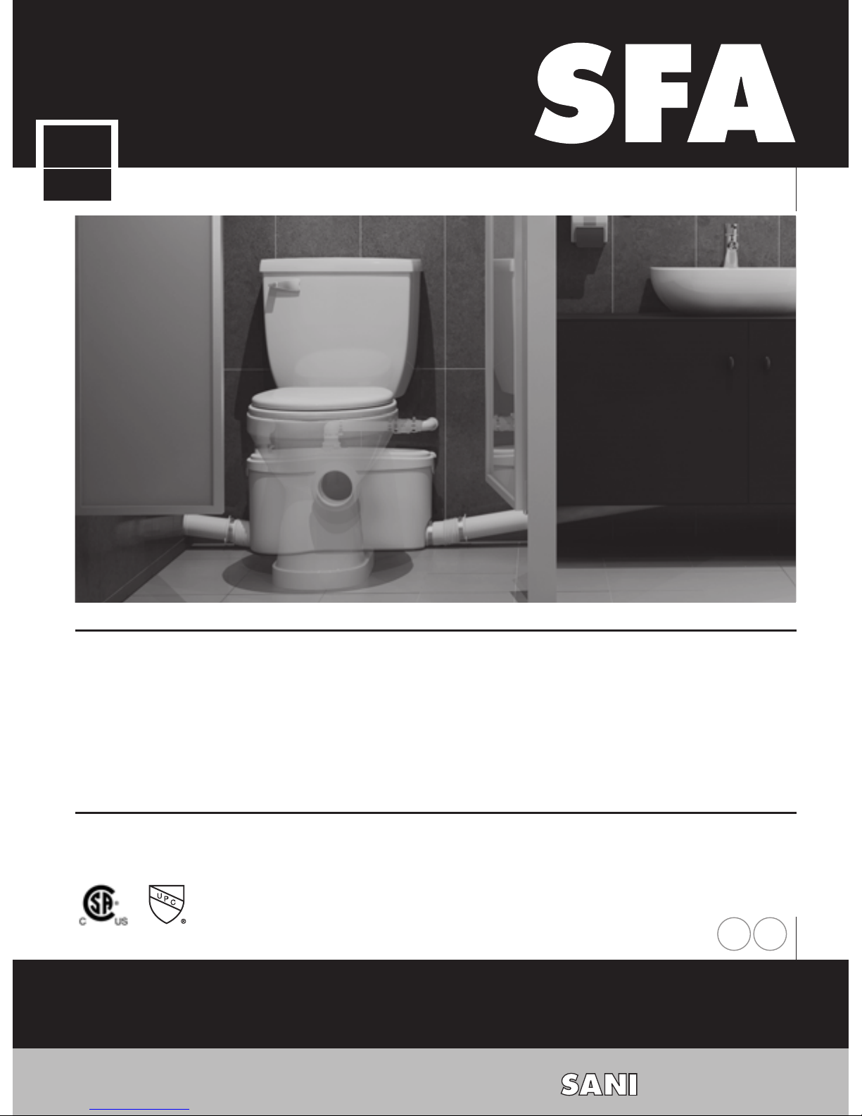
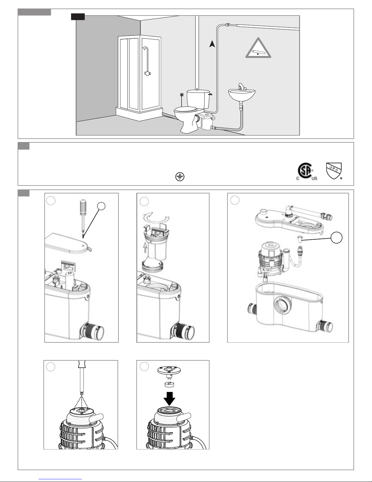
The grinder/pump unit is a residential and commercial pumping system for toilet and bathroom fixtures. As shown in fig
n°1, it can simultaneously receive wastewater from sanitary
fixtures such as a sink, shower, bathtub but only one toilet
per unit. It is also powerful enough to handle wastewater from
a washing machine through an indirect connection (via utility
sink).
The SANIBEST Pro
®
is designed for the disposal of human
waste, toilet paper and water. It is also capable of handling
occasional sanitary articles flushed down the toilet. They are
not intended to be used for the disposal of kitchen waste
or directly from pump appliances such as a dishwasher.
Installed and used correctly, the SANIBEST Pro® will give
consistent and reliable service.
Please note the following warning signs:
« » Possible danger to personnel,
« » Warning of possible electrical hazard,
« » Instructions for use only by qualified professionals,
«WARNING» This is a general warning that failure to
follow instructions could result in poor functioning
of the unit.
2
LIST OF ACCESSORIES
3
DIMENSIONS
4
TECHNICAL DATA
Application 1 toilet + shower/bathtub,
sink
Vertical Pumping Max. 25 Ft
Voltage 110-120 V
Frequency 60 Hz
Amperage Max. 9 Amps
Motor 1 HP
Temperature Max. 104° F
Degree of protection IP44
Net Weight 26 lbs
WARNING: Only installations conforming to the above
specifications are acceptable.
5
PERFORMANCE CURVE
6
VERTICAL/HORIZONTAL PUMPING
COMBINATIONS
7
INSTALLATION
The grinding system must discharge into a minimum 3/4-inch
sanitary drainage pipe. The system will pump up to a maximum of 25 Ft vertically and then across with a 1/4" per foot
gravity fall (minimum) constantly throughout the horizontal run
to the point of discharge. If you require a vertical lift, it should
precede any horizontal run and should commence as near
as possible to the discharge elbow (no more than 18 inches
away). Once you have started the horizontal run, you cannot
change directions in an upward vertical manner.
The unit has fastenings on the bottom of the casing. This is
meant to secure the pump to the floor and prevent it from
turning.
TANK AND WATER SUPPLY CONNECTION
The tank comes with the fill and flush valve already
assembled. The hardware kit to assembled the tank to
the bowl comes included with the system. Ensure that all
screws, nuts, etc are tightened and well secured. Connect
the water supply hose to the bottom connection of the fill
valve.
7a
CONNECTION TO THE TOILET
1
- Stretch the flexible sleeve over the entry connection of
the casing
2
- Secure this connection with the cable tie supplied
3
- Push the metal clamp around the flexible sleeve and
then pull the sleeve over the exit spigot of the bowl
4
- Position the metal clamp at the edge of the flexible
sleeve and secure this by tighten the metal clamp with a
screwdriver
7b
CONNECTION OF THE DISCHARGE PIPE
These systems are provided with a discharge elbow which
has a built-in check valve, a flexible discharge hose, a plastic
coupling and a step-down rubber connection. Follow these
steps to connect to your discharge pipe.
1
- Insert the larger end of the plastic discharge elbow into
the rubber discharge hose coming out from the top of
the pump.
2
- Rotate the discharge to any direction and secure the
base of the elbow with a clamp.
3
- Connect the flexible hose to the smaller end of the discharge elbow and secure with a clamp.
For 3/4" CPVC (22 mm)
4
- Insert the discharge pipe inside the flexible hose and
secure with a clamp.
For 3/4" PVC (28 mm)
4
- Insert the smaller end of the plastic coupling inside the
flexible hose ; secure with clamp.
5
- Connect the step-down rubber connection to the other
end of the plastic coupling; secure with a clamp.
6
- Insert the discharge pipe inside the step-down rubber
connection and secure with clamp.
For 1" PVC (32 mm)
4
- Insert the smaller end of the plastic coupling inside the
flexible hose; secure with clamp.
5
- Connect the step-down rubber connection to the other
end of the plastic coupling; secure with a clamp.
6
- Cut off the end of the step-down rubber connection to fit
the 1” pipe; secure with clamp.
NOTE: Use only 3/4” or 1” pipe for the discharge.
Install a ball valve in the discharge line in order to facilitate the
removal of the unit.
If you want for the unit to pump vertically and horizontally,
you may calculate that 3 Ft of vertical lift is equivalent to 30
Ft of horizontal run. Note that all horizontal runs require a 1/4”
per foot gravity fall.
Each bend or change in direction causes minor losses which
must be deducted from the discharge performance (ie.
reduce discharge height by 3 Ft for each 90 degree turn). Use
long sweeping 90 degree elbows or two 45 degree elbows
back-to-back to create the 90 degree turn. Do not use 90
degree elbows.
The connection to the soil stack or sewer pipe should be
made with an approved wye fitting. If you have any doubts
EN
Fully illustrated step by step instructions are
downloadable on www.saniflo.com or www.saniflo.ca
8
ACTIVATING THE UNIT
Once electrical and plumbing connections have been
made, flush the toilet once. The motor should run from
5 to 10 seconds to clear the waste (depending on the
length and height of the pipe run). If it runs for more than
30 seconds, check that the discharge pipe is not kinked
or blocked or check that the non-return valve is correctly
installed.
Flush the toilet checking that all seals, and connections
are watertight. Check both the discharge pipework from
the unit, and the waste pipes from sink or shower.
WARNING: There should be no dripping of water from
the toilet tank or taps. If there is, this will cause the unit
to activate repeatedly as it pumps the water away.
9
USAGE
The normal domain of application of SFA units only
concerns the disposal of human waste, toilet paper and
water. The SANIBEST Pro
®
is a product conceived for
heavier use, suitable for residential or commercial
applications, and can occasionally accept disposal of
sanitary items such as tampons and sanitary pads.
CAUTIONARY NOTES:
Do not discharge any acids, alkaloids, solvents painting,
paint strippers, food waste, plastic bags, metal such as
nails, hairpins, wood, building materials, kitty litter or
anything that could halt or damage or corrode the unit.
Disregarding the above might damage the unit and shall
void your warranty.
Do not hang bleach blocks or hydrochloride cleaners in
the toilet tank. These solutions have been shown to
deteriorate the plastic and neoprene components of the
flush and fill valves, and may cause leaks. In the event of
a power loss do not use the toilet or any other sanitary
fixture connected to the unit since it will not work until
the power is restored.
The toilet works as a conventional flushing toilet and needs
no maintenance in normal use. However, there is nothing
wrong with cleaning out the unit once a year. Do not use
bleach (Be careful not to let water enter the electrical cord
opening).
The unit starts automatically once the toilet is flushed or the
bath, shower, hand basin, etc. discharge and cease operation once the contents have been pumped away.
Whenever the unit is not in use for long periods of time
(vacation, power failure, maintenance, etc.) turn off the water
supply to the tank and flush the unit to evacuate the water.
No leakage into the bowl should ever be permitted from the
tank.
In areas, which are prone to freezing, the total system must
be properly winterized.This includes the draining of all pipes,
the toilet tank and bowl and the tank. The system is simple
to winterize. Pour a jug of plumbers’ anti-freeze into the tank
and flush the toilet. This will cause the unit to activate and
all remaining water will be replaced by plumber’s anti-freeze.
No parts or labour are warranted when a breakdown occurs
due to freezing.
Ensure that there are no faucets left open. Drops will eventually fill up the pump and the resultant repeated start-stop
of the motor may heat up to such an extent, that the thermal
overload switch may eventually operate and automatically
stop the motor, thus possibly causing a flood.
about this section of the installation, please have a plumber
or trade professional install this for you.
Note: If the end of the discharge pipe is lower than the
base of the pump, siphonage can occur. In order to avoid
siphoning on the discharge line, an anti-siphon valve should
be installed at the highest point of the installation.
7c
CONNECTION OF SANITARY FIXTURES
The unit is equipped with two additional 2” inlets, one on
either side of the case. These inlets, which incorporate an
internal check valve, are use to connect the drain pipe from
other sanitary fixtures.
1
- To connect to the side inlets, use the rubber connector
F
or C and secure with clamps.
2
- If these inlets are not used, plug the unused inlet with
the plug G provided after greasing the joint.
WARNING: Ensure that when connecting a shower or a
bathtub to a SANIBEST Pro®, the platform of the shower
or tub would need to be raised a minimum of 8” from the
floor. You may purchase any shower base or tub, as only
the drain pipe connects to the pump. However, a 2" x 8"
platform would need to be built as this would give enough
space for a p-trap and slope toward the side inlets.
NOTE: The actual distance between the p-trap of the sani-
tary fixture and the macerating unit determines the necessary clearance to install the trap and the elevation required
to ensure the minimum gravity flow of 1/4” per foot.
7d
CONNECTION TO A VENT SYSTEM
The grinder/pump unit must be vented. It has two inlets on
the top of the cover: a 1 1/2” port and a hole of smaller diameter.
The unit must be connected to a vent system according to
the plumbing codes. Place the waste inlet J (provided) on
the 1 1/2” port and clamp it down. Then,
connect the vent pipe and secure with a clamp. Note that all
fixtures connected to the system must also be vented.
WARNING: Do not use an air admittance valve or a
mechanical spring loaded venting device as these devices
are considered one-way valves. The air pressure inside
and outside the macerating unit must be equal.
A “cheater” vent will obstruct the airflow in one direction.
Note: The smaller diameter 1/2” hole must be plugged with
a plastic cap supplied.
7e
EXAMPLE OF SANIBEST Pro® INSTALLATION
7f
CONNECTION TO ELECTRICAL SUPPLY
All wiring should be in accordance with the applicable
electrical code in your territory. The macerating system
requires a single-phase 120-volt, 15 Amp. supply. When
installed in a bathroom, the receptacle should be 40 inches
away (in straight line) from a shower or bathtub. Connect
only to receptacle protected by a ground fault circuit
interrupter (GFCI).
WARNING: risk of electric shock - this pump is suplied with
a grounding conductor and grounding type attachment plug
to reduce the risk of electrical shock. Be certain that it is
connected properly grounded - type receptacle.
10
CARE OF YOUR SANIBEST Pro® UNIT
In order to remove scale and clean the macerator and the
bowl, use Saniflo’s descaler.
• Disconnect the power,
• Pour an amount of descalent in the bowl
• Leave it to stand for 1 or 2 hours,
• Re-connect the power,
• Rinse by operating the flushing system twice.
Carry out the operation once every 3 months on average,
but the frequency may need to be changed depending on
the hardness of the water.
11
FAULT FINDING/REMEDIES
For the most part any inconsistencies in the operation
of the unit will be minor and easily rectified. Please refer
to the chart below. If the problem cannot be easily remedied in
this way. Please call our technical support.
Warning - Always disconnect the electricity supply before
attempting any work on the SANIBEST Pro
®
 Loading...