


 Loading...
Operating
Instructions
|
6, |
EX |
|
|
|
9 |
|
||
|
|
|
- |
|
EX |
SR |
VARIOTEC® |
|
|
|
|
|
||
TEC® |
|
|
|
|
- |
|
|
|
|
103992

Measurable success by Sewerin equipment
You settled on a precision instrument.
A good choice!
Our equipment stands out for guaranteed safety, optimal output and efficiency.
They correspond with the national and international guide-lines.
These operating instructions will help you to handle the instrument quickly and competently.
Please pay close attention to our operating instructions before usage.
In case of further queries our staff is at your disposal at any time.
Yours
Hermann Sewerin GmbH
Robert-Bosch-Straße 3 D-33334 Gütersloh
: +49 - (0) - 52 41/9 34-0 FAX : +49 - (0) - 52 41/9 34-4 44 www.sewerin.com info@sewerin.com
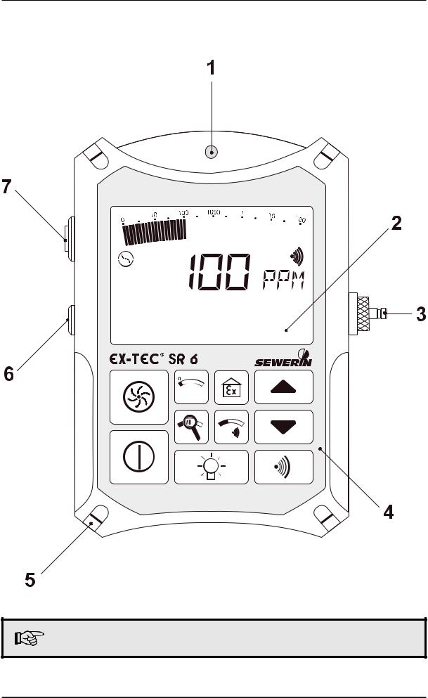
EX-TEC SR 6: illustration
See page 15 for an explanation of individual items
1
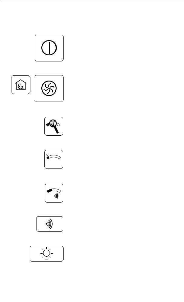
Brief operating instructions
Brief operating instructions: EX-TEC SR 6, VARIOTEC 9-EX
switches the detector on and off
toggles between GAS-WARNING / GASMEASURING modes
toggles between total and optimum measuring ranges
zero-point correction
displays the alarm threshold value
acoustic clearance of the alarm signal
switches LC display illumination on and off (... switches off automatically after about 4 minutes)
2
Operating manual
EX-TEC® SR 6, VARIOTEC® 9-EX
103992 - 04.12.2002
3
For your safety
This product may only be used after the operating instructions have been read and understood and only by appropriately trained operators.
This product may only be used for its designated purpose, and only in industry and trade.
Repair work may only be carried out by appropriately trained persons.
Changes and modifications to the product may only be carried out with the consent of Hermann Sewerin GmbH. Unauthorised modifications to the product render the warranty null and void.
Only accessories from Hermann Sewerin GmbH may be used with this product.
Only spare parts approved by us may be used for repairs.
Hermann Sewerin GmbH bears no liability for damage attributable to noncompliance with these instructions. The terms of warranty and liability of the conditions of sale and delivery of Hermann Sewerin GmbH are not extended by the above.
We reserve the right to make technical modifications in the interests of further development.
Please comply with general safety rules in addition to these instructions!
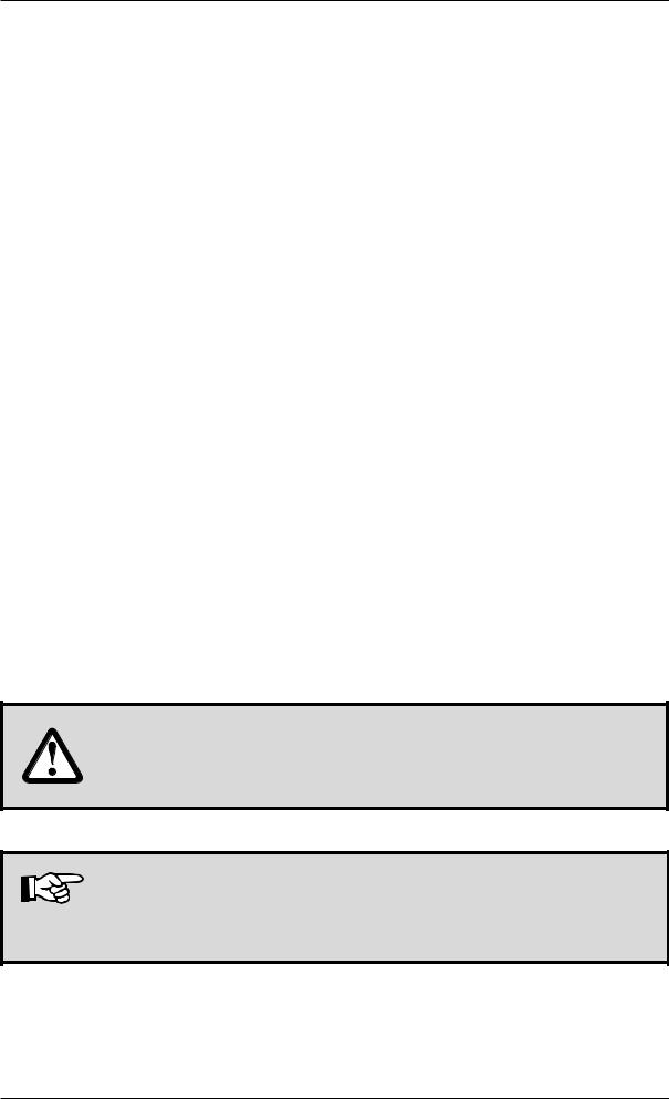
Symbols used:
CAUTION!
This symbol warns of dangers to the user or product.
Note:
This symbol indicates information and tips that go beyond actual operation for the product.
4

Contents |
page |
|
1 |
EX-TEC SR 6, VARIOTEC 9-EX system |
|
1.1 |
Models .......................................................................................... |
7 |
1.2 |
Test certificates ............................................................................ |
8 |
1.3 |
Charging equipment ..................................................................... |
9 |
1.4 |
Carrying equipment .................................................................... |
10 |
1.5 |
Probe systems ............................................................................. |
11 |
1.6 |
Test equipment ........................................................................... |
13 |
2 Safety
2.1 Safety instructions ....................................................................... |
14 |
3 |
Measuring operation |
|
3.1 |
Model overview........................................................................... |
15 |
3.2 |
Switching on ............................................................................... |
16 |
3.3 |
Illumination and contrast ............................................................. |
17 |
3.3.1 |
Operating hours in measuring operation .................................... |
18 |
3.4 |
Pump operation .......................................................................... |
19 |
3.5 |
Alarm signal and volume ............................................................ |
20 |
3.5.1 |
Automatic alarm reactivation....................................................... |
20 |
3.6 |
Alarm threshold value ................................................................. |
21 |
3.7 |
Switching measuring ranges ...................................................... |
22 |
3.8 |
Location / gas injection / blanketing ............................................ |
23 |
3.9 |
Delayed-action indicator ............................................................. |
24 |
3.10 |
Zero-point correction .................................................................. |
25 |
3.11 |
Gas-warning mode ..................................................................... |
25 |
3.12 |
Battery alarm ............................................................................... |
27 |
3.13 |
Switching off ............................................................................... |
27 |
4 |
Charging operation |
|
4.1 |
Charging and charge maintenance............................................. |
28 |
4.2 |
Spontaneous discharge ............................................................. |
29 |
5

Contents |
page |
|
5 |
Testing and maintenance |
|
5.1 |
Function testing, testing display accuracy .................................. |
30 |
5.2 |
Test equipment ........................................................................... |
33 |
5.3 |
Test gases .................................................................................. |
35 |
5.4 |
Function testing .......................................................................... |
36 |
6 |
Settings menu |
|
6.1 |
Setting the ppm sensor .............................................................. |
38 |
6.2 |
Setting the LEL sensor ............................................................... |
40 |
6.3 |
Setting the VOL sensor .............................................................. |
41 |
6.4 |
Setting the measurement unit (%LEL range language) .............. |
43 |
6.5 |
Setting 10 ppm sensitivity .......................................................... |
45 |
6.6 |
Activating the ETHANE box........................................................ |
46 |
6.7 |
Interface mode ........................................................................... |
46 |
6.8 |
Checking the LC display............................................................. |
47 |
6.9 |
Leaving the settings menu ......................................................... |
47 |
7 |
Technical aspects |
|
7.1 |
Technical notes........................................................................... |
48 |
7.2 |
Technical data ............................................................................. |
49 |
7.3 |
Error messages .......................................................................... |
52 |
7.4 |
Wearing parts ............................................................................. |
54 |
Appendix |
|
|
EC-type-examination certificates ......................................................... |
55 |
|
Declarations of conformity ................................................................... |
60 |
|
Test report ............................................................................................ |
62 |
|
6

1 EX-TEC SR 6, VARIOTEC 9-EX system
1 EX-TEC SR 6, VARIOTEC 9-EX system
1.1 Models
EX-TEC SR 6 (explosion-proof)
Gas detection
above-ground gas detection for pipeline monitoring (ppm range)
Interior installations
leak detection for pipelines in buildings (ppm range)
Gas warning
monitoring proximity to the lower explosion limit (%LEL range)
Location
concentration measurement in probe holes (vol.% range)
Gas injection and blanketing concentration measurement in pipelines (vol.% range)
VARIOTEC 9-EX (explosion-proof)
Gas detection
above-ground gas detection for pipeline monitoring (ppm range)
Interior installations
leak detection for pipelines in buildings (ppm range)
Location
concentration measurement in probe holes (vol.% range)
Gas injection and blanketing concentration measurement in pipelines (vol.% range)
7

1 EX-TEC SR 6, VARIOTEC 9-EX system
1.2Test certificates
Passive explosion protection
The EX-TEC SR 6 and VARIOTEC 9-EX models are explosion-proof in accordance with European norms (CENELEC):
EC prototype test certificate: PTB 96 ATEX 2166
Identification mark: |
II 2 G EEx ib d IIB T3 |
Testing institution: |
Physikalische-Technische |
|
Bundesanstalt, Brunswick |
Active explosion protection
The EX-TEC SR 6 has also been tested for functional safety in the gaswarning field:
Test report: |
PFG no. 41300897 |
Testing institution: |
DMT - Gesellschaft for Forschung |
|
und Prüfung mbH, Essen |
The test certificates can be found on and after page 55.
8
1 EX-TEC SR 6, VARIOTEC 9-EX system
1.3Charging equipment
The EX-TEC SR 6 and the VARIOTEC 9-EX can be charged either in the workshop or in the standby vehicle:
HS charging adapter
to hold the detector, with a connection socket for the plug-in power pack or a vehicle adapter
230V plug-in power pack
to connect the HS HS charging adapter to a 230-volt mains supply
12V vehicle adapter
to connect the HS charging adapter to a 12-volt vehicle battery
24V vehicle adapter
(not shown) to connect the HS charging adapter to a 24-volt vehicle battery
9

1 EX-TEC SR 6, VARIOTEC 9-EX system
1.4Carrying equipment
TRIANGEL carrying system
a quick and easy way of carrying the detector, consisting of a carrying strap and neck-pad
front view |
side view |
rear view |
CROSS-STRAP carrying system
a comfortable way to carry the detector for longer periods, consisting of 2 carrying straps crossed at the back
front view |
side view |
rear view |
10
1 EX-TEC SR 6, VARIOTEC 9-EX system
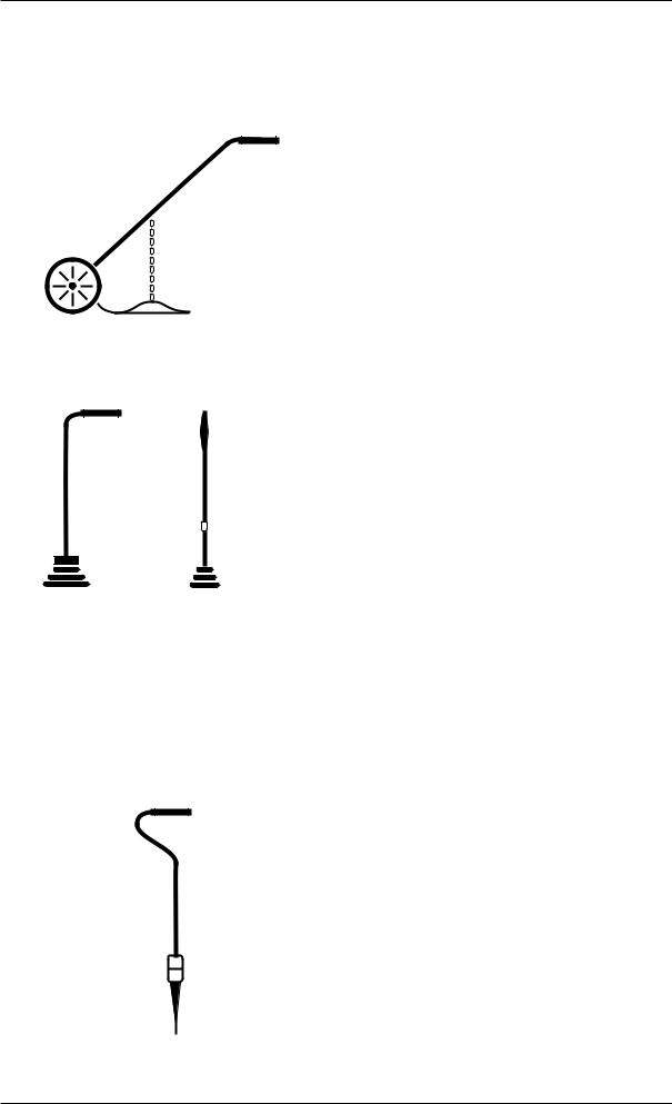
1.5Probe systems
- Pipe-monitoring probes -
Carpet probe
for checking stable surfaces. The sample is drawn into an excrescence in a neoprene mat in contact with the surface with no extraneous emissions
Bell probe, telescopic bell probe
for checking unstable and overgrown surfaces.
It can be used in confined spaces, e.g. between parked cars or in front gardens
- Location probes-
Location probe
for measuring concentrations in probe holes,
with a rigid rubber cone to seal off the probe hole and
2 different probe tips (length 245 mm or 345 mm)
11
1 EX-TEC SR 6, VARIOTEC 9-EX system
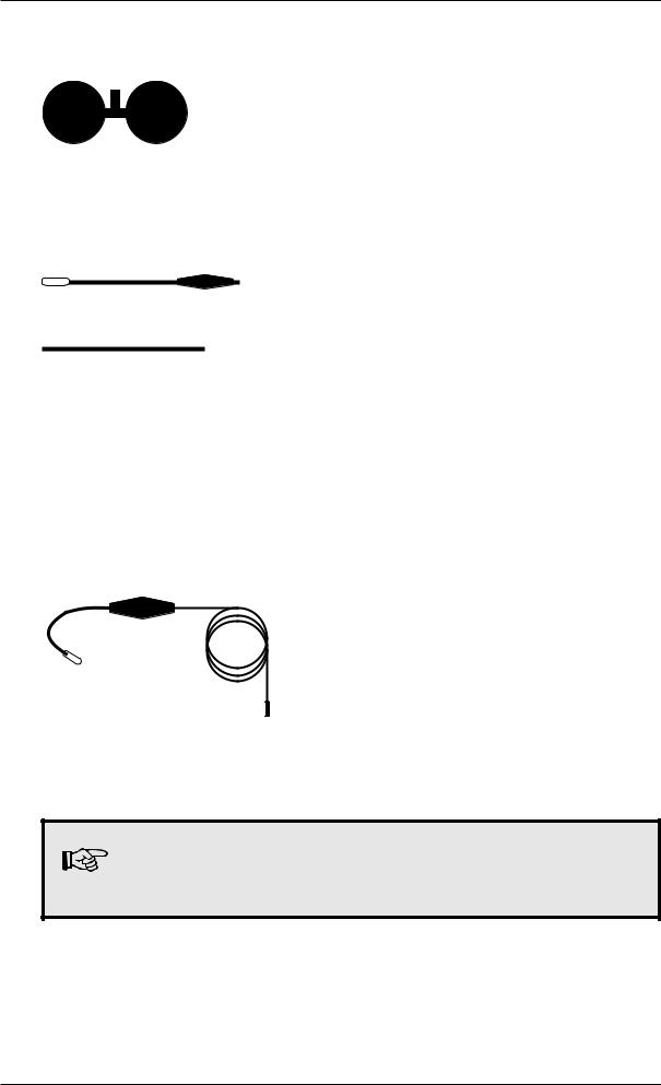
- Probes for use in enclosed spaces -
Floater probe
for measuring concentrations in shafts,
floater with intake orifice and hose connection
Divisible manual probe
for use with unenclosed pipes or at inaccessible locations, measuring concentrations in containers, overall length 900 mm
- Probes for interior installations -
Flexible manual probes for use with interior pipework,
grip with flexible swan-neck and probe hose, overall lengths 360 mm or 660 mm
Except with the carpet probe, a probe hose should always be used with a hydrophobic filter.
12
1 EX-TEC SR 6, VARIOTEC 9-EX system
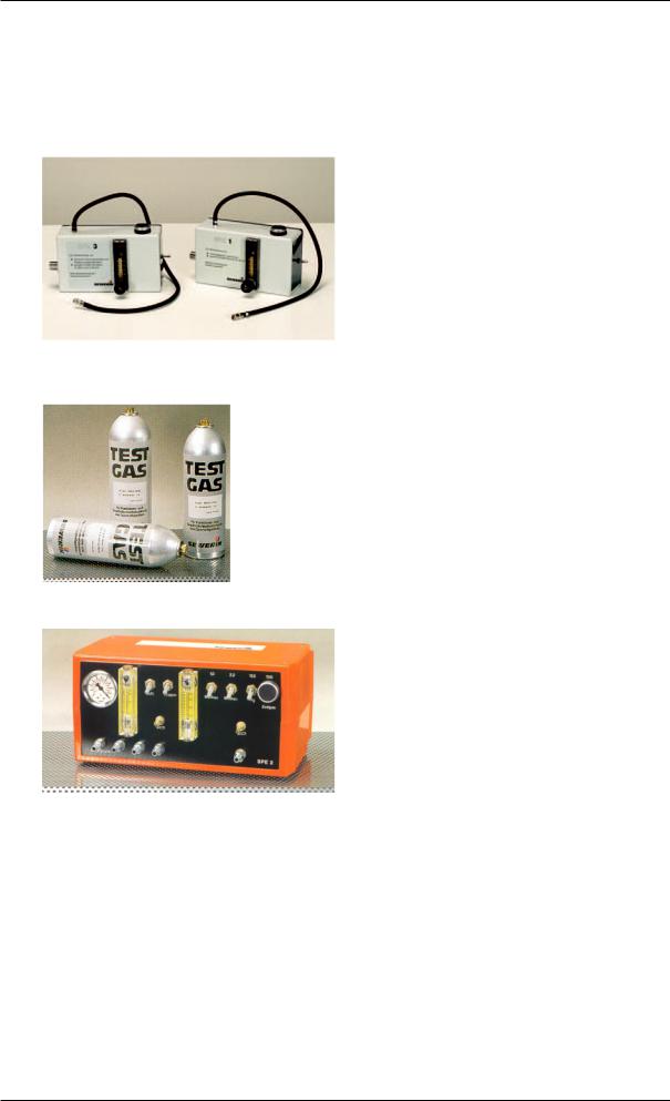
1.6Test equipment
The following equipment is available for monitoring and testing the pump power and sensitivity of the EX-TEC SR 6 and VARIOTEC 9-EX:
SPE1 and SPE3 testers
for mobile use including in-vehicle use,
with connections for SEWERIN test-gas bottles, flow meter, release button and connection hose
Test-gas bottles
for testing and adjusting display sensitivity,
various test-gas concentrations in 1-litre bottles at pressures of about 12 bar
SPE2 tester
for non-mobile use in the workshop, with connections for several SEWERIN pressure cylinders, pressure and flow meter, release button and connection hoses
Pressure cylinders
(not shown) for testing and adjusting display sensitivity, various test-gas concentrations in 0.4 / 2.0 / 10.0 litre steel cylinders at pressures of 100-150 bar
13

2 Safety
2 Safety
2.1 Safety instructions
Always use original SEWERIN accessories with the EX-TEC SR 6 and VARIOTEC 9-EX
Always use a probe hose with a hydrophobic filter
Observe the permissible operating temperature range of minus 10 °C to plus 40 °C
The EX-TEC SR 6 and VARIOTEC 9-EX must not be recharged in areas exposed to the danger of explosion
Test gases may only be used in well-ventilated spaces
The EX-TEC SR 6 and VARIOTEC 9-EX satisfy the limits of the EMV regulation. When using it near (mobile) radio equipment please also follow the instructions in the manuals for that equipment
14

3 Measuring operation
3 Measuring operation
3.1 Model overview
Fold out the illustration inside the front cover
Item |
description |
function |
|
|
|
1 |
alarm lamp |
optical warning on: |
|
|
breaching alarm thresholds |
|
|
display of error messages |
|
|
|
2 |
LC display |
display of: |
|
|
gas concentrations |
|
|
menu items |
|
|
operating conditions |
|
|
error messages |
|
|
|
3 |
probe connection |
connection for: |
|
|
probe hose |
|
|
tester |
|
|
|
4 |
keypad |
detector operation |
|
|
|
5 |
attachment |
for carrying systems: |
|
|
Triangel |
|
|
cross-strap |
|
|
|
6 |
outlet |
for the gas sample |
|
|
|
7 |
buzzer |
acoustic warning on: |
|
|
reaching alarm thresholds |
|
|
display of error messageses |
15
3 Measuring operation
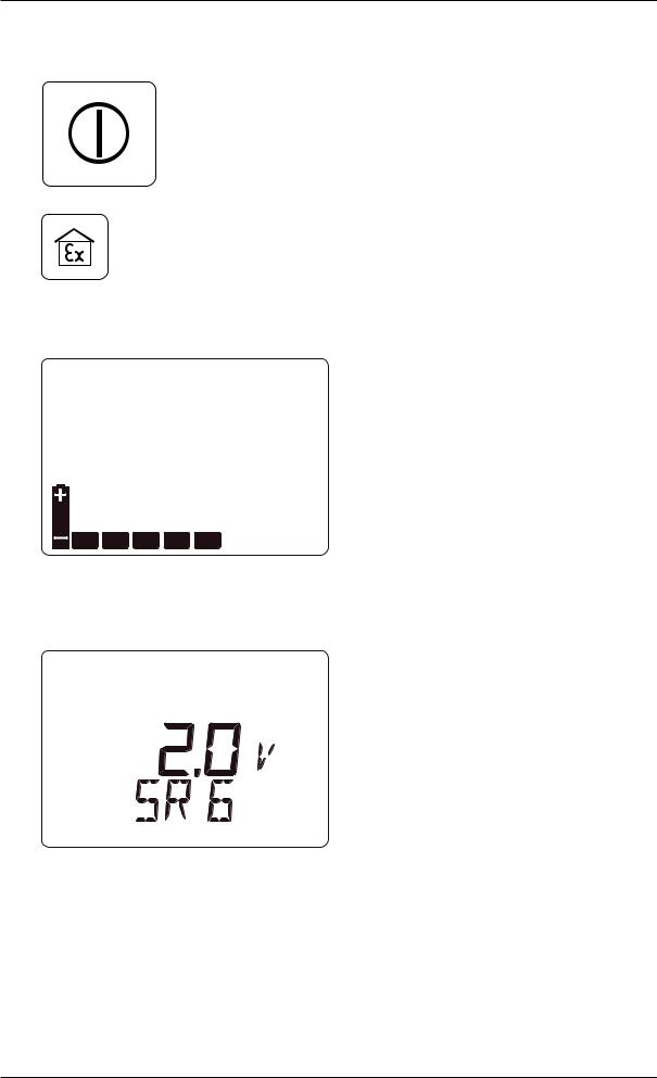
3.2 Switching on
hold the on/off button down for about 2 seconds
or, on the SR 6 only, hold the gaswarning button down for about 2 seconds to start the detector in gas-warning mode (see p. 25 ff.)
the optical and acoustic control signals (items 1 and 7) operate for about 2 seconds
available operating hours are displayed in the form of bars (e.g. 5 hours)
theintegralpumprunsatfullpower
the software version number (e.g. 2.0) and detector type (SR 6) are displayed
16
3 Measuring operation
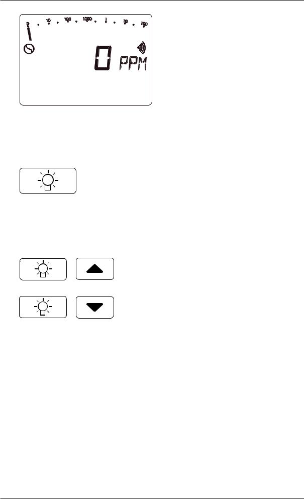
wait for the zero point to establish itselfinfreshair(approx.1minute):
display:  0 PPM
0 PPM
(after flashing stops)
3.3 Illumination and contrast
pressing the light button switches the LC DISPLAY illumination on and off
the illumination automatically switches off approx. 4 minutes after being switched on
simultaneously pressing the light button and a cursor button increases or reduces the contrast of the LC display
17

3 Measuring operation
3.3.1 Operating hours in measuring operation
simultaneously pressing both cursor buttons in measuring operation displays the operating hours still available (e.g. 5 hours)
this display (battery symbol and bars) disappears automatically after about 10 seconds
18
Loading...