

Page 1
Operating
Instructions
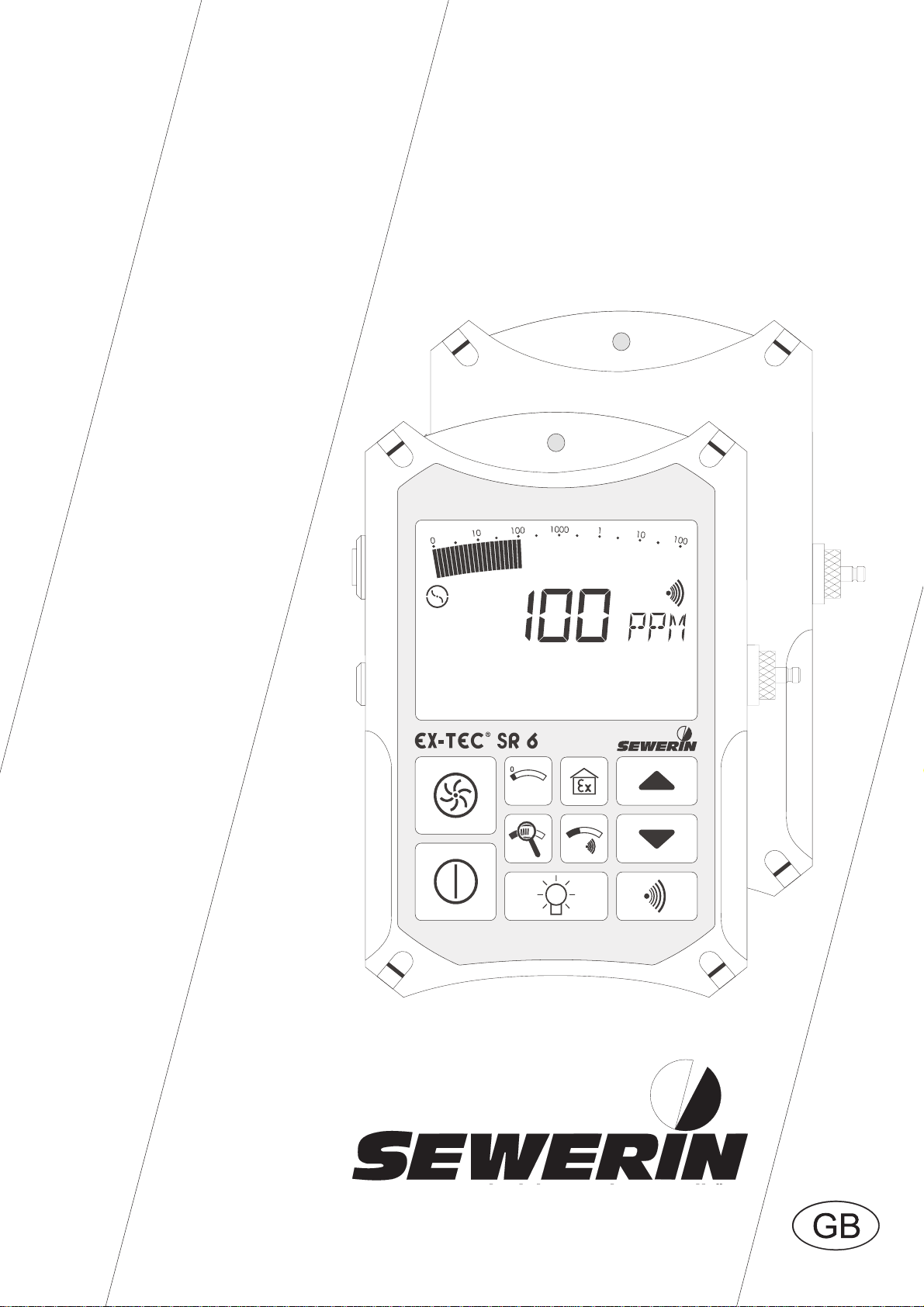
EX-TEC® SR 6,
VARIOTEC® 9-EX
103992
Page 2

Measurable success by Sewerin equipment
You settled on a precision instrument.
A good choice!
Our equipment stands out for guaranteed safety, optimal output and efficiency.
They correspond with the national and international guide-lines.
These operating instructions will help you to handle the instrument quickly and
competently.
Please pay close attention to our operating instructions before usage.
In case of further queries our staff is at your disposal at any time.
Yours
Hermann Sewerin GmbH
Robert-Bosch-Straße 3
D-33334 Gütersloh
: +49 - (0) - 52 41/9 34-0
FAX : +49 - (0) - 52 41/9 34-4 44
www.sewerin.com
info@sewerin.com
Page 3
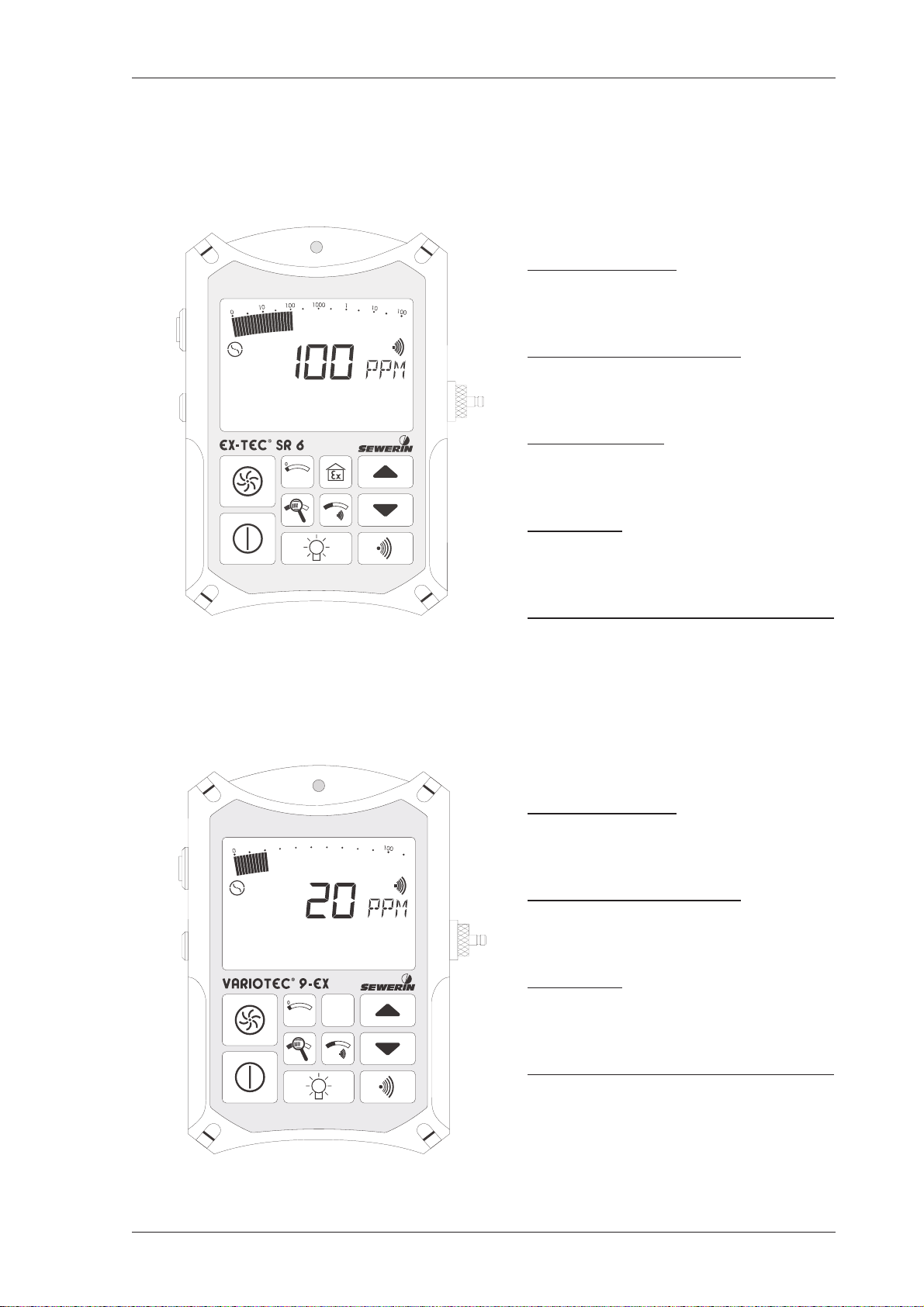
EX-TEC SR 6: illustration
See page 15 for an explanation of individual items
1
Page 4
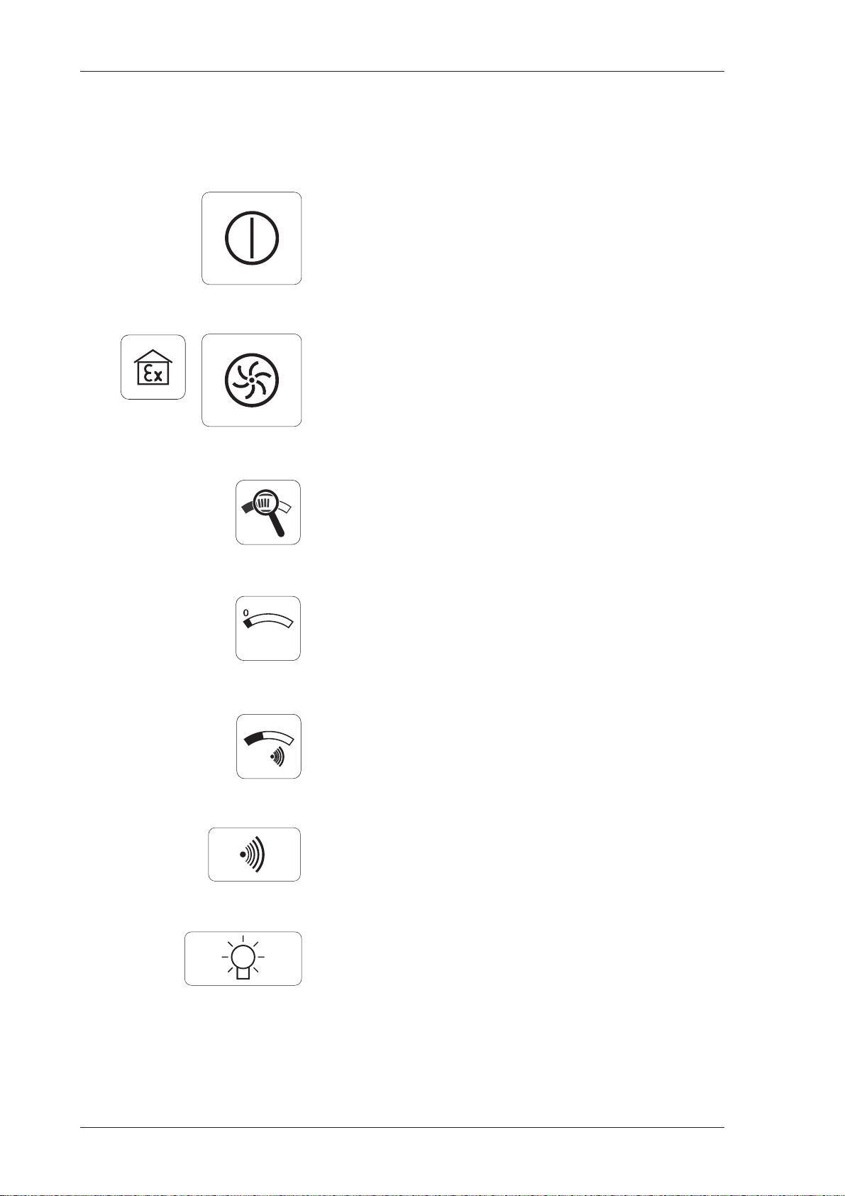
Brief operating instructions
Brief operating instructions:EX-TEC SR 6, VARIOTEC 9-EX
switches the detector on and off
toggles between GAS-WARNING / GASMEASURING modes
toggles between total and optimum
measuring ranges
zero-point correction
displays the alarm threshold value
acoustic clearance of the alarm signal
switches LC display illumination on and off
(... switches off automatically after about 4
minutes)
2
Page 5

Operating manual
EX-TEC® SR 6,
VARIOTEC® 9-EX
103992 - 04.12.2002
3
Page 6
For your safety
This product may only be used after the operating instructions have been
read and understood and only by appropriately trained operators.
This product may only be used for its designated purpose, and only in
industry and trade.
Repair work may only be carried out by appropriately trained persons.
Changes and modifications to the product may only be carried out with
the consent of Hermann Sewerin GmbH. Unauthorised modifications to
the product render the warranty null and void.
Only accessories from Hermann Sewerin GmbH may be used with this
product.
Only spare parts approved by us may be used for repairs.
Hermann Sewerin GmbH bears no liability for damage attributable to non-
compliance with these instructions. The terms of warranty and liability of
the conditions of sale and delivery of Hermann Sewerin GmbH are not
extended by the above.
We reserve the right to make technical modifications in the interests of
further development.
Please comply with general safety rules in addition to these instructions!
Symbols used:
CAUTION!
This symbol warns of dangers to the user or product.
Note:
This symbol indicates information and tips that go beyond
actual operation for the product.
4
Page 7

Contents page
1 EX-TEC SR 6, VARIOTEC 9-EX system
1.1 Models.......................................................................................... 7
1.2 Test certificates ............................................................................ 8
1.3 Charging equipment ..................................................................... 9
1. 4 Carrying equipment .................................................................... 10
1.5 Probe systems .............................................................................11
1.6 Test equipment........................................................................... 13
2 Safety
2. 1 Safety instructions ....................................................................... 14
3 Measuring operation
3. 1 Model overview ........................................................................... 15
3. 2 Switching on ............................................................................... 16
3.3 Illumination and contrast ............................................................. 17
3.3.1 Operating hours in measuring operation .................................... 18
3.4 Pump operation .......................................................................... 19
3. 5 Alarm signal and volume ............................................................ 20
3.5.1 Automatic alarm reactivation....................................................... 20
3. 6 Alarm threshold value ................................................................. 21
3. 7 Switching measuring ranges ...................................................... 22
3. 8 Location / gas injection / blanketing............................................ 23
3.9 Delayed-action indicator ............................................................. 24
3.10 Zero-point correction .................................................................. 25
3. 11 Gas-warning mode ..................................................................... 25
3.12 Battery alarm............................................................................... 27
3.13 Switching off............................................................................... 27
4 Charging operation
4. 1 Charging and charge maintenance............................................. 28
4.2 Spontaneous discharge ............................................................. 29
5
Page 8

Contents page
5 Testing and maintenance
5. 1 Function testing, testing display accuracy.................................. 30
5.2 Test equipment........................................................................... 33
5.3 Test gases.................................................................................. 35
5. 4 Function testing .......................................................................... 36
6 Settings menu
6. 1 Setting the ppm sensor .............................................................. 38
6. 2 Setting the LEL sensor............................................................... 40
6. 3 Setting the VOL sensor.............................................................. 41
6. 4 Setting the measurement unit (%LEL range language).............. 43
6. 5 Setting 10 ppm sensitivity .......................................................... 45
6. 6 Activating the ETHANE box........................................................ 46
6.7 Interface mode ........................................................................... 46
6. 8 Checking the LC display ............................................................. 47
6. 9 Leaving the settings menu ......................................................... 47
7 Technical aspects
7.1 Technical notes ........................................................................... 48
7. 2 Technical data............................................................................. 49
7.3 Error messages.......................................................................... 52
7.4 Wearing parts ............................................................................. 54
Appendix
EC-type-examination certificates ......................................................... 55
Declarations of conformity................................................................... 60
Test report ............................................................................................ 62
6
Page 9
1 EX-TEC SR 6, VARIOTEC 9-EX system
1 EX-TEC SR 6, VARIOTEC 9-EX system
1.1 Models
EX-TEC SR 6 (explosion-proof)
Gas detection
above-ground gas detection for
pipeline monitoring (ppm range)
Interior installations
leak detection for pipelines in
buildings (ppm range)
Gas warning
monitoring proximity to the lower
explosion limit (%LEL range)
Location
concentration measurement in
probe holes (vol.% range)
Gas injection and blanketing
concentration measurement in
pipelines (vol.% range)
VARIOTEC 9-EX (explosion-proof)
Gas detection
above-ground gas detection for
pipeline monitoring (ppm range)
Interior installations
leak detection for pipelines in
buildings (ppm range)
Location
concentration measurement in
probe holes (vol.% range)
Gas injection and blanketing
concentration measurement in
pipelines (vol.% range)
7
Page 10

1 EX-TEC SR 6, VARIOTEC 9-EX system
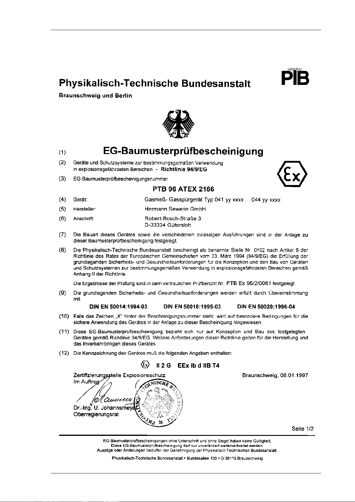
1.2 Test certificates
Passive explosion protection
The EX-TEC SR 6 and VARIOTEC 9-EX models are explosion-proof
in accordance with European norms (CENELEC):
EC prototype test certificate: PTB 96 ATEX 2166
Identification mark: II 2 G EEx ib d IIB T3
Testing institution: Physikalische-Technische
Bundesanstalt, Brunswick
Active explosion protection
The EX-TEC SR 6 has also been tested for functional safety in the gas-
warning field:
Test report: PFG no. 41300897
Testing institution: DMT - Gesellschaft for Forschung
und Prüfung mbH, Essen
The test certificates can be found on and after page 55.
8
Page 11
1 EX-TEC SR 6, VARIOTEC 9-EX system
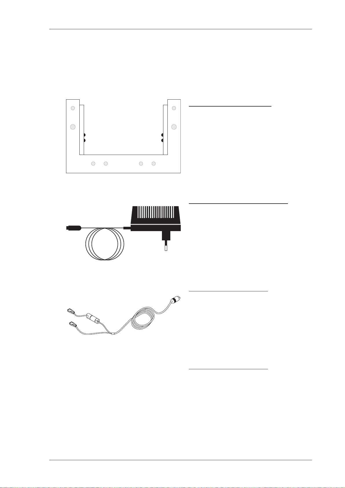
1.3 Charging equipment
The EX-TEC SR 6 and the VARIOTEC 9-EX can be charged either in
the workshop or in the standby vehicle:
HS charging adapter
to hold the detector, with a
connection socket for the plug-in
power pack or a vehicle adapter
(not shown)
230V plug-in power pack
to connect the HS HS charging
adapter to a 230-volt mains supply
12V vehicle adapter
to connect the HS charging adapter
to a 12-volt vehicle battery
24V vehicle adapter
to connect the HS charging adapter
to a 24-volt vehicle battery
9
Page 12

1 EX-TEC SR 6, VARIOTEC 9-EX system
1.4 Carrying equipment
TRIANGEL carrying system
a quick and easy way of carrying the detector , consisting of a carrying
strap and neck-pad
front view side view rear view
CROSS-STRAP carrying system
a comfortable way to carry the detector for longer periods, consisting
of 2 carrying straps crossed at the back
10
front view side view rear view
Page 13
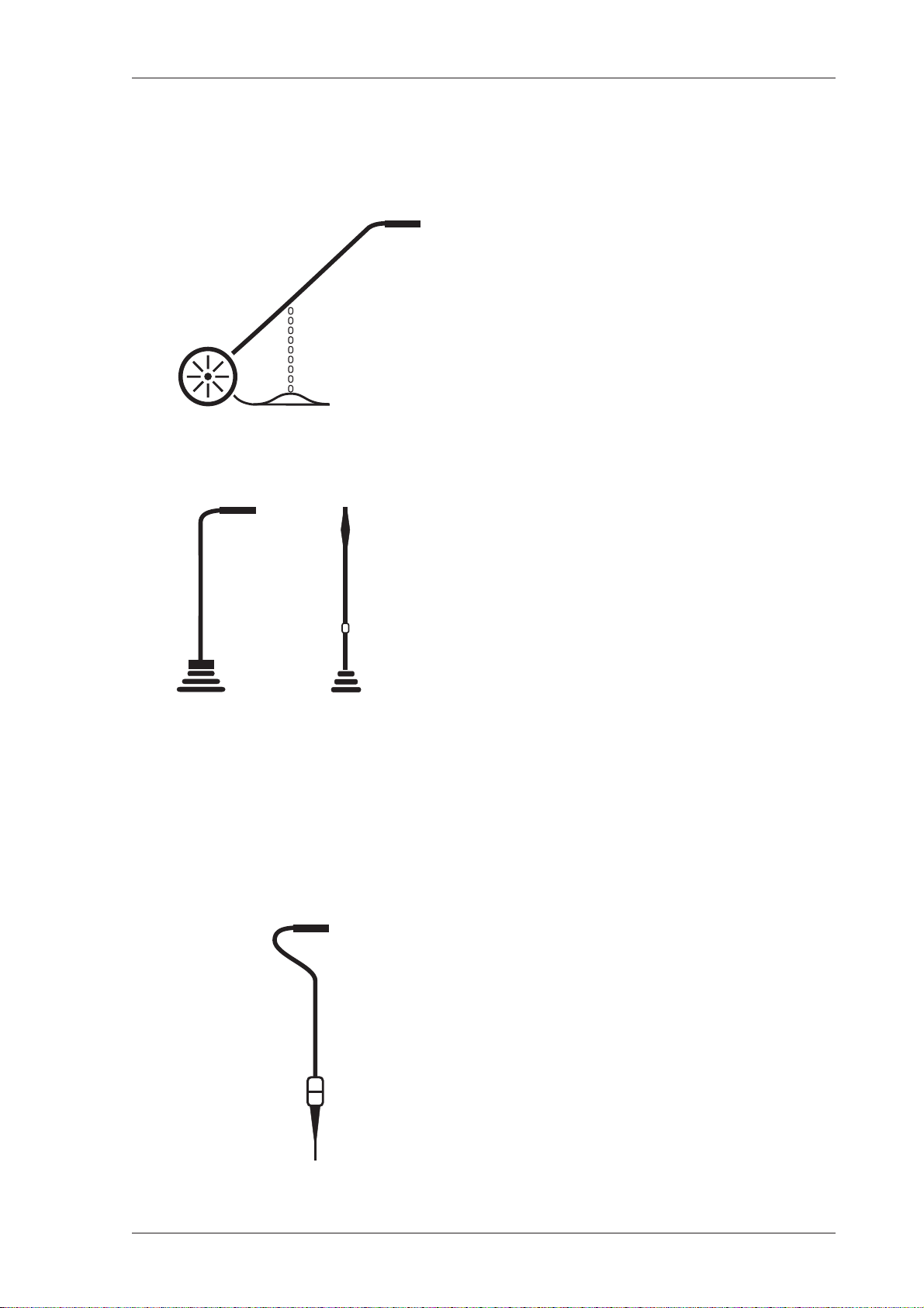
1.5 Probe systems
- Pipe-monitoring probes -
1 EX-TEC SR 6, VARIOTEC 9-EX system
Carpet probe
for checking stable surfaces.
The sample is drawn into an
excrescence in a neoprene mat in
contact with the surface with no
extraneous emissions
- Location probes-
Bell probe,
telescopic bell probe
for checking unstable and
overgrown surfaces.
It can be used in confined spaces,
e.g. between parked cars or in front
gardens
Location probe
for measuring concentrations in
probe holes,
with a rigid rubber cone to seal off
the probe hole and
2 different probe tips (length 245
mm or 345 mm)
11
Page 14

1 EX-TEC SR 6, VARIOTEC 9-EX system
- Probes for use in enclosed spaces -
Floater probe
for measuring concentrations in
shafts,
floater with intake orifice and hose
connection
Divisible manual probe
for use with unenclosed pipes or
at inaccessible locations,
measuring concentrations in
containers, overall length 900 mm
- Probes for interior installations -
Flexible manual probes
for use with interior pipework,
grip with flexible swan-neck and
probe hose, overall lengths 360 mm
or 660 mm
Except with the carpet probe, a probe hose should
always be used
with a hydrophobic filter.
12
Page 15
1 EX-TEC SR 6, VARIOTEC 9-EX system
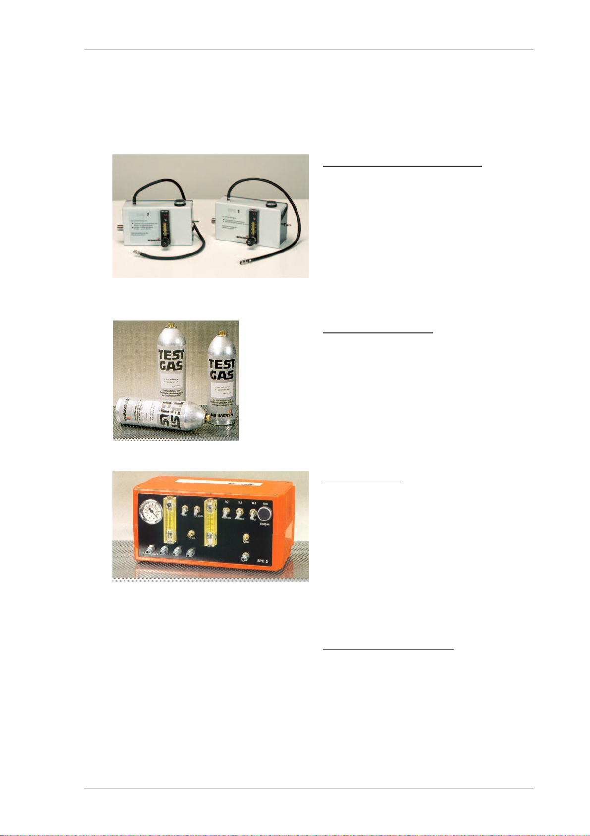
1.6 Test equipment
The following equipment is available for monitoring and testing the
pump power and sensitivity of the EX-TEC SR 6 and VARIOTEC 9-EX:
SPE1 and SPE3 testers
for mobile use including in-vehicle
use,
with connections for SEWERIN
test-gas bottles, flow meter,
release button and connection
hose
Test-gas bottles
for testing and adjusting display
sensitivity,
various test-gas concentrations in
1-litre bottles at pressures of about
12 bar
SPE2 tester
for non-mobile use in the
workshop, with connections for
several SEWERIN pressure
cylinders, pressure and flow meter ,
release button and connection
hoses
(not shown)
Pressure cylinders
for testing and adjusting display
sensitivity, various test-gas
concentrations in 0.4 / 2.0 / 10.0
litre steel cylinders at pressures of
100-150 bar
13
Page 16
2 Safety
2 Safety
2.1 Safety instructions
Always use original SEWERIN accessories with the
EX-TEC SR 6 and VARIOTEC 9-EX
Always use a probe hose with a hydrophobic filter
Observe the permissible operating temperature
range of minus 10 °C to plus 40 °C
The EX-TEC SR 6 and VARIOTEC 9-EX must not be
recharged in areas exposed to the danger of
explosion
Test gases may only be used in well-ventilated
spaces
14
The EX-TEC SR 6 and VARIOTEC 9-EX satisfy the
limits of the EMV regulation. When using it near
(mobile) radio equipment please also follow the
instructions in the manuals for that equipment
Page 17

3 Measuring operation
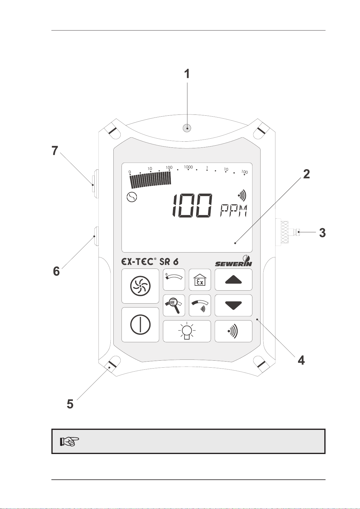
3.1 Model overview
Fold out the illustration inside the front cover
Item description function
1 alarm lamp optical warning on:
breaching alarm thresholds
display of error messages
2 LC display display of:
gas concentrations
menu items
operating conditions
error messages
3 Measuring operation
3 probe connection connection for:
probe hose
tester
4 keypad detector operation
5 attachment for carrying systems:
Triangel
cross-strap
6 outlet for the gas sample
7 buzzer acoustic warning on:
reaching alarm thresholds
display of error messageses
15
Page 18
3 Measuring operation
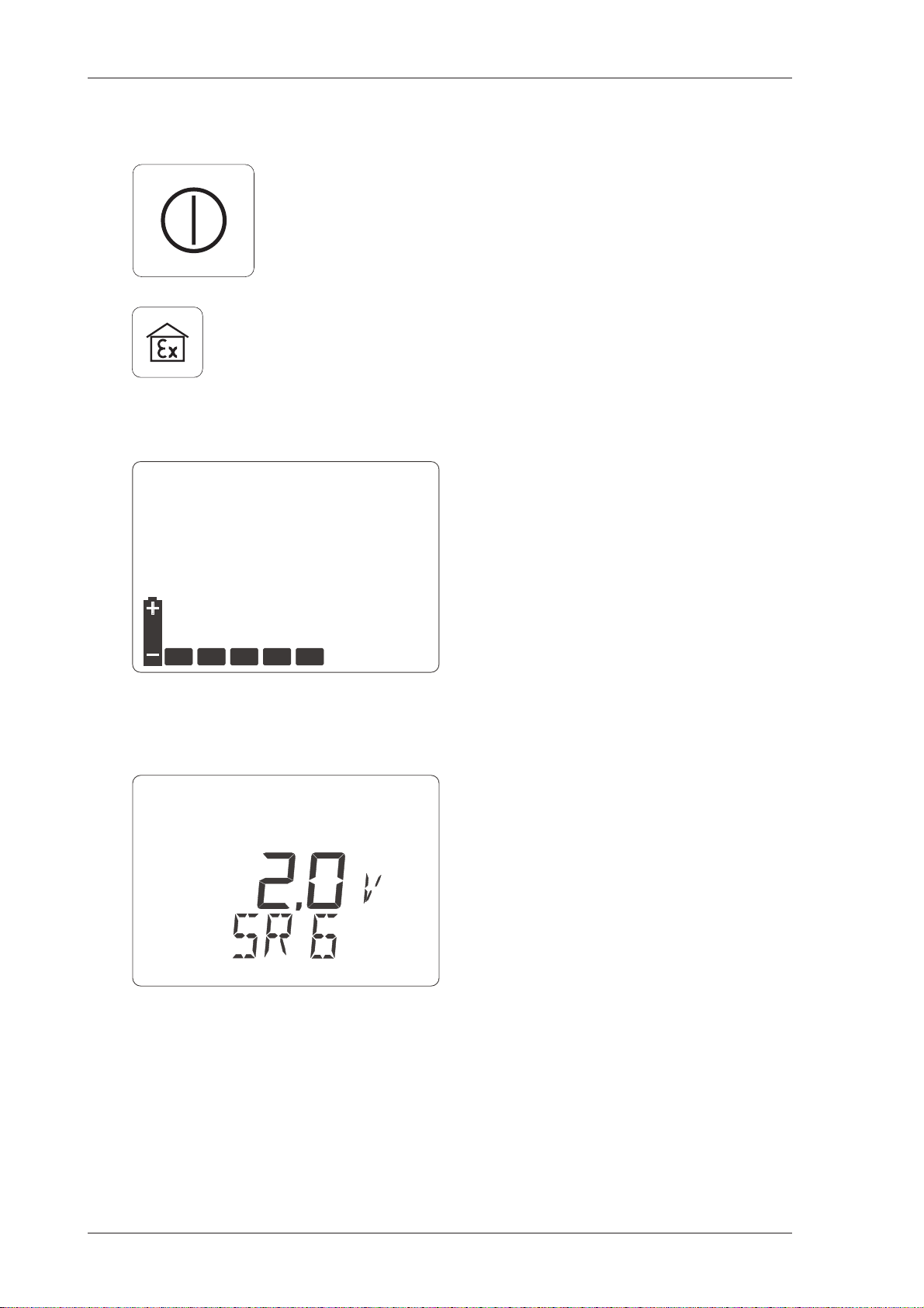
3.2 Switching on
hold the on/off button down for
about 2 seconds
or, on the SR 6 only, hold the gas-
warning button down for about
2 seconds to start the detector in
gas-warning mode (see p. 25 ff.)
the optical and acoustic control
signals (items 1 and 7) operate
for about 2 seconds
available operating hours are
displayed in the form of bars (e.g.
5 hours)
the integral pump runs at full power
the software version number
(e.g. 2.0) and detector type
(SR 6) are displayed
16
Page 19
3.3 Illumination and contrast
3 Measuring operation
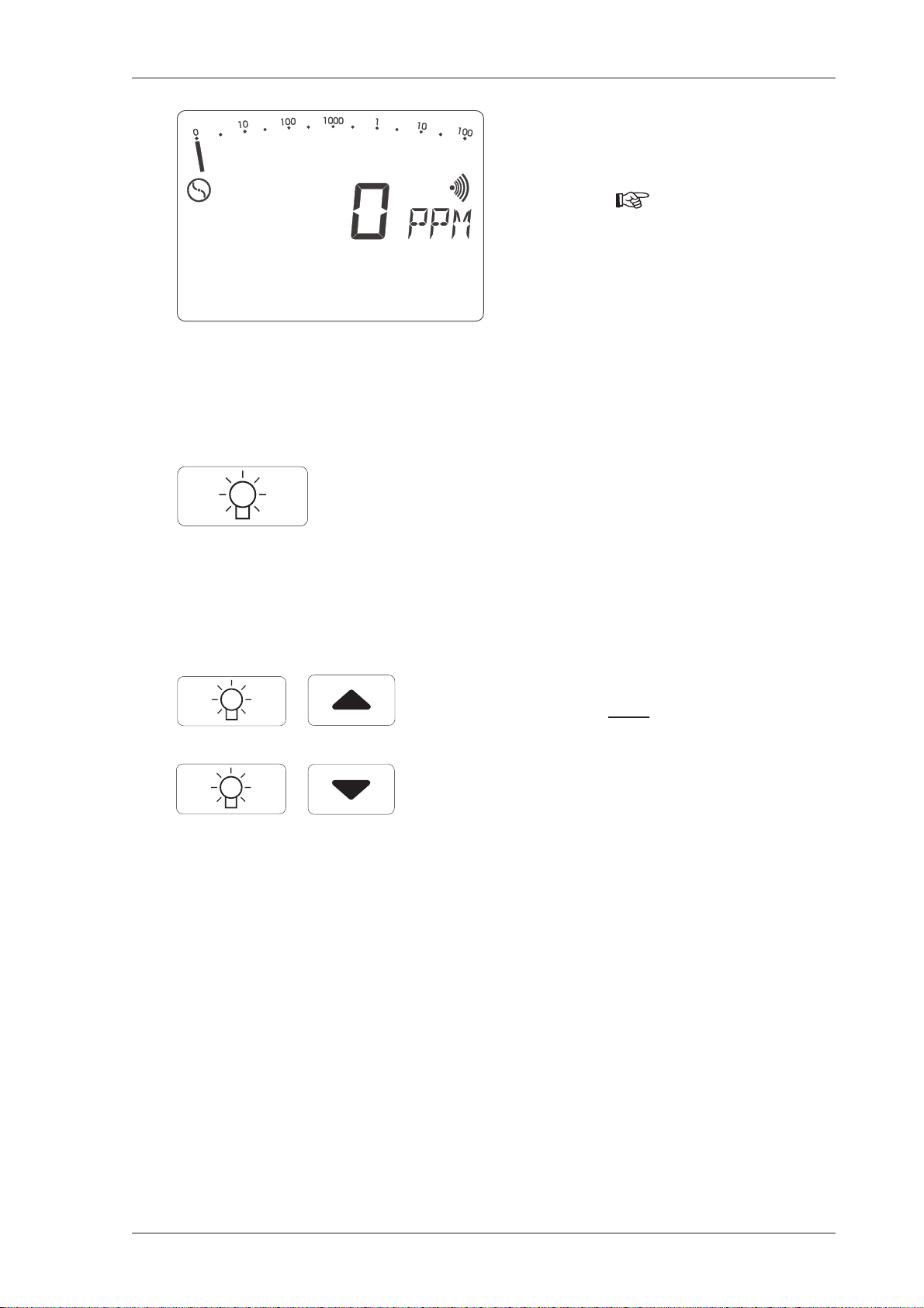
wait for the zero point to establish
itself in fresh air (approx. 1 minute):
display: 0 PPM
(after flashing stops)
pressing the light button
switches the LC DISPLAY
illumination on and off
the illumination automatically
switches off approx. 4 minutes
after being switched on
simultaneously pressing the light
button
and a cursor button
increases or reduces the contrast
of the LC display
17
Page 20
3 Measuring operation
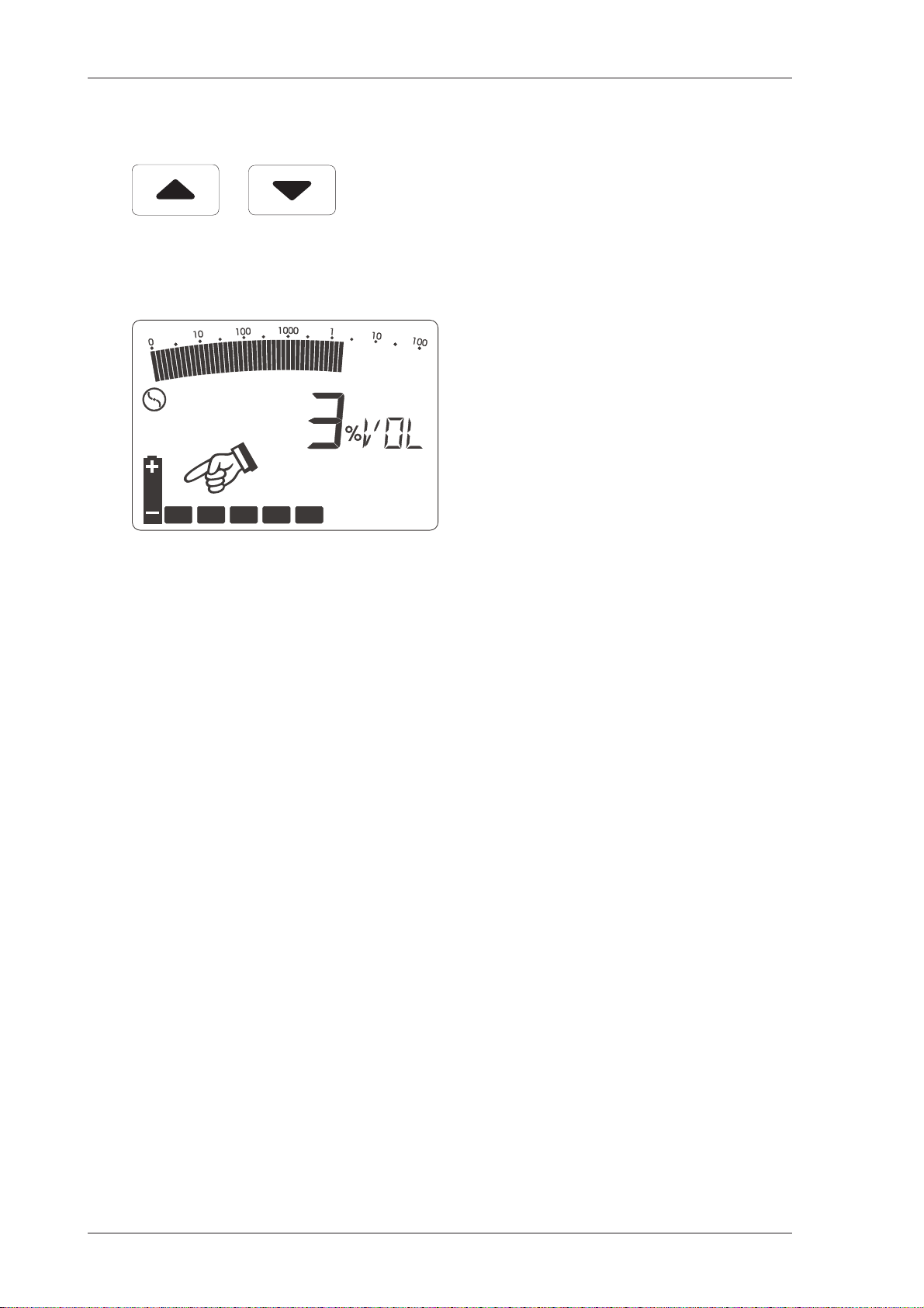
3.3.1
Operating hours in measuring operation
simultaneously pressing both
this display (battery symbol and
cursor buttons in measuring
operation displays the operating
hours still available (e.g. 5 hours)
bars) disappears automatically
after about 10 seconds
18
Page 21

3.4 Pump operation
3 Measuring operation
pressing the pump button
switches the pump on and off
this turns the corresponding
symbol on or off in the LC display
(item 2)
this enables you to monitor the
pump function
Changing the pump power
simultaneously pressing the
pump button
increases or reduces the pump
power
always use maximum pump
power for above-ground gas
detection in pipelines
and a cursor button
Gas detection
Interior installations
always use minimum pump
power for leak detection in
pipelines in buildings
19
Page 22

3 Measuring operation
3.5 Alarm signal and volume
pressing the signal button
switches the alarm signal on and
off
this turns the corresponding
symbol on or off in the LC display
(item 2)
this enables you to check the
alarm signal
3.5.1Automatic alarm reactivation
simultaneously pressing the
signal button and a cursor button
increases or reduces the volume
of the buzzer (item 7)
if you turn off an alarm with the
signal button, the alarm signal is
automatically reactivated after
about 60 seconds
the corresponding symbol then
reappears in the LC display (item
2)
20
this avoids the problem of the
operator forgetting to reactivate
the alarm signal
Page 23

3.6 Alarm threshold value
3 Measuring operation
hold down the threshold value
button
and the alarm threshold value
flashes on the scale (here 10 PPM)
holding down the the detector's
value button while pressing a
cursor button increases or
reduces the alarm threshold value
this value is preserved even when
the detector is switched off
21
Page 24

3 Measuring operation
3.7 Switching measuring ranges
the detectors have both an
analogue scale (above - here
showing the full measurement
range) and a digital display
(below); both displays show the
same concentration (here 70 PPM)
the scale is logarithmic, ranging
from:
0 PPM ... 100 %VOL
the scale can display low
concentrations in magnified form;
the reading is also shown in the
digital display
pressing the zoom button
toggles between the full and the
optimum measuring ranges
depending on the concentration,
switching between the following
measuring ranges is automatic:
0 ... 10 ppm
0 ... 100 ppm
0 ... 1000 ppm
0 ... 1 %VOL
0 ... 100 %VOL
in this example the optimum
measuring range is 0 ... 100 ppm
22
you can switch manually to your
preferred display range by
holding down the zoom button
and pressing a cursor button
Page 25
3 Measuring operation
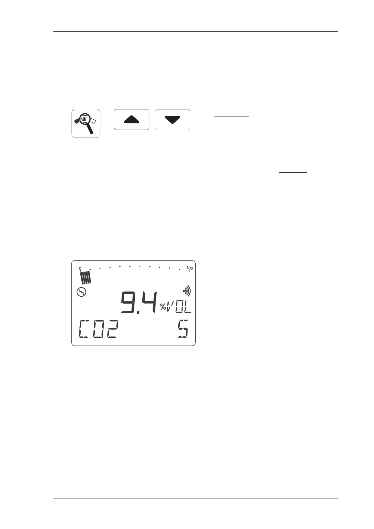
3.8 Location / gas injection / blanketing
To carry out a location, gas injection (concentration increase to
100 vol.%) or blanketing (concentration reduction to 0 vol.%), proceed as
follows:
manually select the measuring
range 0.0 ... 100 %VOL with the
zoom button and the cursor
buttons
this is the only measuring range
in which you can
reliably monitor
location, gas injection and
blanketing
manually switching to the
measuring range 0.0 ... 100 %VOL
is the only way to make sure that
the CO
component is also shown
2
in the display
in this example the readings are:
9.4 %VOL CH
and 5 %VOL CO
4
2
23
Page 26

3 Measuring operation
3.9 Delayed-action indicator
To make it easier to compare concentrations - for location purposes,
for example - the maximum value is displayed in the form of a flashing
delayed-action indicator.
this remains in the LC display
(item 2) for about 4 minutes, or if
the concentration rises it is
updated
the delayed-action indicator
disappears when the zoom button
is pressed
24
Page 27

3.10Zero-point correction
3 Measuring operation
if the detector fails to reach its
zero point even after being
thoroughly flushed with fresh air ,
you can manually correct the zero
point by pressing the zero point
button
the reading display flashes while
the correction is under way
measurement may not continue
until after the flashing stops
3.11 Gas-warning mode
This function is only available on the EX-TEC SR 6
this function is switched on by
pressing the gas-warning
button
this button can also be used to
switch the detector on direct
25
Page 28

3 Measuring operation
this measuring range is used to
monitor proximity to the LEL
(lower explosion limit)
a stable zero point is reached
after about 8 seconds' warm-up
time
the pump runs at minimum power,
and the acoustic operating signal
(item 7) sounds every 5 seconds
when the pre-set threshold of
10% LEL = 0.45 vol.% (CH4) is
reached, the advance alarm is
triggered both optically (item 1)
and acoustically (item 7)
the advance alarm is an
intermittent tone quite distinct
from the operating signal;
it ceases after a certain period
and cannot be cleared
if the concentration exceeds
100 % LEL of methane (100
% LEL = 4.40 vol.%) the main
alarm is triggered both optically
(item 1) and acoustically (item 7)
26
Page 29

3.12Battery alarm
3 Measuring operation
the main alarm is a continuous
tone quite distinct from the
operating signal;
it continues indefinitely and
cannot be cleared
Leaving gas-warning mode:
hold down the pump button for
about 2 seconds or switch the
detector off
3.13 Switching off
if the battery symbol appears in
the LC display, at least 15 minutes'
operating time remains;
after that the detector must be
recharged
in gas-warning mode the battery
alarm sounds as a double beep
to distinguish it from the operating
signal
Press the on/off button for about
2 seconds
the optical and acoustic
monitoring signals (items 1 and
7) operate for about 2 seconds
remaining operating hours are
displayed in the form of bars
27
Page 30

4 Charging operation
4 Charging operation
4.1 Charging and charge maintenance
Charging
When fully charged the detector has a
maximum of 8 hours' operating
time with the pump running.
To charge the detector you will need the HS charging adapter (see
illustration), which can be used either in the workshop or the emergency
vehicle.
The following connection sockets
can be found on the side of the
charging adapter:
230-V plug-in power pack
12-V vehicle adapter
24-V vehicle adapter.
Switch off the EX-TEC SR 6 or VARIOTEC 9-EX and place it in the
charger. A display on the following lines appears:
the detector still has 5 operating
hours left (= 5 bars) and will take
another 3 hours to be fully
recharged
if it is fully charged, all the bars
appear and the numerical display
is blank
Charge maintenance
As soon as the detector is fully charged it automatically switches to
charge maintenance. It can be left in the charging adapter until the next
time it is needed.
28
Page 31

4 Charging operation
4.2 Spontaneous discharge
If the detector is not placed in the charger when it is switched off, the
nickel-cadmium battery spontaneously discharges, thus reducing the
available operating hours.
After a maximum of 30 days the indicator shows that there are no
operating hours left, and it must be recharged.
Short periods of operation and prolonged disuse
may lead in the long term to the so-called "memory
effect", in which the display indicates a higher battery
capacity than is actually available.
This can be avoided by fully discharging the EX-TEC
SR 6 or V ARIOTEC 9-EX regularly (e.g. once a month),
i.e. leaving it switched on until it automatically switches
off, then recharging it.
29
Page 32

5 Testing and maintenance
5 Testing and maintenance
Gas-warning instruments must always be tested by
the operator before the gas-warning facility is used
and before every working shift. Topics covered by
this test include:
checking the battery charge
display with neutral gas and test gas
(leaflet T 023/BG chemicals: "Gas-warning instruments
for explosion protection - operation and maintenance")
DIN EN 50073 provides that portable gas-warning
instruments (such as the EX-TEC SR 6) must be
tested immediately before use in accordance with
the operating manual. This must include testing the
zero point and display sensitivity with a fieldcalibration device and test gas.
5.1 Function testing, testing display accuracy
The test must also cover ancillary equipment. The tests listed above
and other activities must be documented, and the documentation
preserved for at least 1 year. The required and prescribed instrument
tests in accordance with DVGW G 465-4 (Technical reports, note) are
divided into the following sections:
30
Page 33

5 Testing and maintenance
What? Who? When?
function test user before the utility company
commences work
display-accuracy expert or daily to half-yearly
test (adjustment) specialist firm
upkeep SEWERIN, annually or whenever a
(maintenance, utility-company defect occurs
repair if necessary) expert
Function test
This is the simplest form of instrument test. Carried out by the user
before use, it comprises the following points:
external condition including probe systems
function of the operating controls
battery-charge check
pump and intake-channel inspection
pump function
mechanical/electrical zero point
display-sensitivity test by gas admission
Function control and sensitivity test ("10 ppm test")
In addition, DVGW worksheet G 465-1 provides that gas-detection
instruments used for systematic pipeline inspection must undergo a
sensitivity test with 10 ppm conditioned (i.e. humidified) test gas.
Using the SPE 3 tester ensures that the test gas is conditioned.
Depending on the circumstances, this test may have to be carried out
(and documented) several times per working day.
31
Page 34

5 Testing and maintenance
Checking display sensitivity (adjustment)
The testing frequency must be specified as a function of the sensors
fitted and the use of the detector . It can be anywhere between daily and
half-yearly.
Testing must be carried out by an expert on the operator's own staff,
by a specialist firm or by Sewerin itself.
The test gas described in section 5.3 must be used. The explosionprotection rules (BGR 104 EX-RL) must be complied with, as must the
principles for testing the functionability of non-fixed gas-warning
instruments for explosion protection (ZH 1/108.1) and the guidelines
for the selection, installation, use and maintenance of instruments for
the detection and measurement of combustible gases or oxygen (DIN
EN 50073/VDE 0400, part 6).
The function test should be carried out at the same time.
Upkeep - maintenance and repair
The detector must be maintained at least once a year by SEWERIN
Service, a specialist firm authorised by SEWERIN or an authorised
specialist of the gas-supply company.
Certificates must be issued accordingly.
The test disc on the detector
confirms when maintenance was
last carried out and indicates the
next scheduled date (e.g. 5/02 =
May 2002).
Annual maintenance and repair must cover at least the specialist care
and adjustment of the detector and the replacement of components
with a limited useful life.
32
Where detectors are explosion-proof the applicable
regulations must be observed
Maintenance specialists must have been trained and
instructed by Sewerin
Page 35

5 Testing and maintenance
5.2 Test equipment
The pump power, zero point and sensitivity should be tested with the
SPE 1 or SPE 3 testers and a suitable test gas:
Fig. 1
The SPE 1 is used to test:
pump power
the zero point in the %LEL and %VOL ranges
sensitivity in the %LEL and %VOL ranges.
It is used with the following test gases:
methane CH
: 1.00 vol.%
4
2.20 vol.% (50% LEL)
100 vol.%
carbon dioxide CO2: 100 vol.%
33
Page 36

5 Testing and maintenance
Fig. 2
The SPE 3 tester is used to test:
pump power
the zero point in the PPM range
sensitivity in the PPM range.
It is used with the following test gases:
methane CH4: 10 ppm
100 ppm
1000 ppm
34
Page 37

5 Testing and maintenance
5.3 Test gases
The following test gases are used to function-test the detectors:
CH
EX-TEC SR 6 ppm range 10 ppm
(gas detection, 100 ppm
interior 1000 ppm
installations) 1.00 vol.%
%LEL range 2.20 vol.%
(gas warning) (50% LEL)
vol.% range 100 vol.% 100 vol.%
(location,
gas injection,
blanketing)
VARIOTEC 9-EX ppm range 10 ppm
(gas detection, 100 ppm
interior 1000 ppm
installations) 1.00 vol.%
4
CO
2
vol.% range 100 vol.% 100 vol.%
(location,
gas injection,
blanketing)
35
Page 38

5 Testing and maintenance
5.4 Function testing
Proceed as follows:
screw the selected test-gas bottle onto the tester as far as it will
go (fig. 1/2 - item 2)
connect the probe nipple of the detector (item 3) to the tester
hose (fig. 1/2 - item 1)
switch the detector on: the pump draws in fresh air through the
tester (fig. 1/2 - item 4)
maximise the flow rate with the needle valve (fig. 1/2 - item 5) -
it must be greater than 50 l/h (fig. 1/2 - item 6)
wait for the detector to warm up and reach a stable zero point
press the tester's release button (fig. 1/2 - item 3) and correct
the flow rate to the value with fresh air (fig. 1/2 - item 6)
hold it down until the displayed concentration has reached a
stable value
Admissible display values with methane CH4 test gas:
test gas 10 ppm : > 10 ppm
test gas 100 ppm : 70 ... 140 ppm
test gas 1000 ppm : 800 ... 1.200 ppm
test gas 1.00 vol.% : 0.80 ... 1.20 vol.%,
test gas 2.20 vol.% : 2.00 ... 2.40 vol.% (45 ... 55% LEL)
test gas 100 vol.% : 98 ... 102 vol.%
Admissible display values with carbon dioxide CO2 test gas :
test gas 100 vol.% : 98 ... 102 vol.%
If display values are outside these tolerances the detector must be
readjusted (cf. section 6.0: Settings menu).
36
Page 39

6 Settings menu
6 Settings menu
The EX-TEC SR 6 and VARIOTEC 9-EX detectors are factory-set for
all measuring ranges.
You can adjust each of the ranges using appropriate test gases (one
for each range).
All the following adjustment steps are shown on an
EX-TEC SR 6, the more comprehensive version.
They also apply to the VARIOTEC 9-EX.
Testing procedure
Connect your detector (switched off) to the SPE 1 or SPE 3 tester and
a test gas.
now press these 3 buttons
simultaneously
Once the number of available operating hours has been displayed the
detector is in adjustment mode:
the software version number (e.g.
V1.7) is displayed and the pump
runs at maximum power
the reading display flashes until
the zero point of the sensor has
been automatically established
37
Page 40

6 Settings menu
once the zero point has been set,
press the cursor-up button to
move to the next step
6.1 Setting the ppm sensor
10 ppm setting
Now release the 10 ppm methane CH4 test gas from the SPE 3 tester.
wait for the display to stabilise
confirm the setting with the on/off
button (OK appears in the LC
display)
turn off the test-gas feed
press the cursor-up button to
move to the next step
100 ppm setting (not absolutely essential)
Now release the 100 ppm methane CH
test gas from the SPE 3
4
tester.
wait for the display to stabilise
confirm the setting with the on/off
button (OK appears in the LC
display)
38
turn off the test-gas feed
press the cursor-up button to
move to the next step
Page 41

6 Settings menu
1000 ppm setting (not absolutely essential)
Now release the 1000 ppm methane CH4 test gas from the SPE 3
tester.
wait for the display to stabilise
confirm the setting with the on/off
button (OK appears in the LC
display)
turn off the test-gas feed
press the cursor-up button to
move to the next step
NB: change the tester
1.00 vol.% setting
Now release the 1.00 vol.% methane CH4 test gas from the SPE 1
tester.
wait for the display to stabilise
confirm the setting with the on/off
button (OK appears in the LC
display)
turn off the test-gas feed
press the cursor-up button to
move to the next step
39
Page 42

6 Settings menu
6.2 Setting the LEL sensor
0 %LEL setting
Now set the zero point of the % LEL range with fresh air using the
SPE 1 tester.
wait for the display to stabilise
confirm the setting with the on/off
button (OK appears in the LC
display)
50 %LEL setting
Now release:
2.20 vol.% methane CH
via the SPE 1 tester.
press the cursor-up button to
move to the next step
test gas = 50 %LEL
4
wait for the display to stabilise
confirm the setting with the on/off
button (OK appears in the LC
display)
40
turn off the test-gas feed
press the cursor-up button to
move to the next step
Page 43

6.3 Setting the VOL sensor
6 Settings menu
0 vol.% setting
Now set the zero point of the vol.% range with fresh air using the
SPE 1 tester.
wait for the display to stabilise
confirm the setting with the on/off
button (OK appears in the LC
display)
press the cursor-up button to
move to the next step
100 vol.% methane (CH4) setting
Now release the:
100 vol.% methane (CH
) test gas
4
via the SPE 1 tester.
wait for the display to stabilise
confirm the setting with the on/off
button (OK appears in the LC
display)
turn off the test-gas feed
press the cursor-up button to
move to the next step
41
Page 44

6 Settings menu
100 vol.% carbon dioxide (CO 2) setting
Now release the:
100 vol.% carbon dioxide (CO
via the SPE 1 tester.
) test gas
2
wait for the display to stabilise
confirm the setting with the on/off
button (OK appears in the LC
display)
turn off the test-gas feed
press the cursor-up button to
move to the next step
42
Page 45

6 Settings menu
6.4 Setting the measurement unit (%LEL range language)
Repeatedly pressing the on/off button enables you to select among the
following displays in the %LEL range:
%UEG -
Untere Explosionsgrenze (German)
%LEL - Lower Explosive Limit (English)
%LIE - Limite Inférieure d´Explosion (French)
%VOL - concentration display in vol.% (German/English)
%GAZ - concentration display in vol.% (French)
confirm the display, e.g. %UEG,
with the on/off button (OK appears
in the LC display)
this display is retained even when
the detector is switched off
press the cursor-up button to
move to the next step
43
Page 46

6 Settings menu
%VOL range language
By repeatedly pressing the on/off button you can choose between the
following displays in the vol.% range:
%VOL - concentration display in vol.% (German/English)
%GAZ - concentration display in vol.% (French)
confirm the display, e.g. %VOL,
with the on/off button (OK appears
in the LCD display)
this setting is retained even when
the detector is switched off
press the cursor-up button to
move to the next step
44
Page 47

6 Settings menu
6.5 Setting 10 ppm sensitivity
Depending on whether synthetic or fresh air is used for the zero-point
adjustment, you must always achieve sensitivity of > 5 ppm when using
10 ppm methane CH
test gas.
4
To this end you can select from the following amplification ratios in the
10 ppm range by repeatedly pressing the on/off switch:
1.0 x 10 ppm - 100% amplification
1.2 x 10 ppm - 120% amplification
1.5 x 10 ppm - 150% amplification (factory setting)
confirm the selected amplification
(e.g. 1.5 x 10 PPM) with the on/
off button
press the cursor-up button to
move to the next step
45
Page 48

6 Settings menu
6. 6 Activating the ETHANE BOX
If you are using an EX-TEC SR 6 or VARIOTEC 9-EX in conjunction
with the ETHANE BOX, this function must be enabled:
pressing the on/off button
switches the function on and off:
ETHANE 1 = (on)
ETHANE 0 = (off)
press the cursor-up button to
move to the next step
For further details see the ETHANE BOX operating manual.
6.7 Interface mode
if your detector has an external
RS 232 interface, you can enable
it:
RS 232 1 = (on)
RS 232 0 = (off)
if your detector lacks this interface,
the interface function must be
deactivated
46
press the cursor-up button to
move to the next step
Page 49

6 Settings menu
6.8 Checking the LC display
With this function you can check whether all elements of the LC display
are operating normally.
confirm the LCD check with the
on/off button
6.9 Leaving the settings menu
press the cursor-up button to
return to the first step
press the pump button for about
2 seconds
hold down the gas-warning button
for about 2 seconds to return to
gas-warning mode or
press the on/off button to switch
the detector off
47
Page 50

7 Technical aspects
7 Technical aspects
7.1 Technical notes
Oxygen concentration
In order to guarantee electrical safety the detectors may not be used
in an oxygen concentration exceeding 21 vol.%.
An oxygen deficiency may lead to deviations from the correct reading.
Cleaning
Clean the detectors only with a damp cloth. No solvents, benzenes or
similar substances may be used.
Static charging
Generally speaking electrostatic charging should be avoided. Objects
with no electrostatic earth (including, for example, metallic housings
with no earth connection) are not protected from charges resulting from
dust, vapour flows and the like.
Fine dust filters
There are fine dust filters in the screw-on probe connector (item 3) and
in most probes.
The filters can be cleaned by tapping or blowing them to remove the
dust.
After the filters have been cleaned, they must be
replaced in exactly the same position as before
Heavily-soiled filters should be replaced by new
ones (accessories)
Sensor sensitivity
The sensors are deleteriously affected by gaseous components of
silicones, oils and phosphate esters, which irreversibly reduce their
sensitivity.
Pollution of the measuring environment by halogens, burnt neoprene,
PVC, trichloroethylene and the like also weakens the sensitivity of the
sensors, but in this case it can be regenerated.
48
Page 51

7 Technical aspects
7.2 Technical data
Models : EX-TEC SR 6
VARIOTEC 9-EX
Setting : methane CH4 /carbon dioxide CO
Measuring systems
- ppm range : semiconductor sensor
- %LEL range : heat-tinting sensor
- vol.% range : 2 thermal-conductivity sensors
CH4 measuring range : 10 ppm - 1 ppm steps
100 ppm - 2 ppm steps
1000 ppm - 20 ppm steps
1 vol.% - 0.02 vol.% steps
10 vol.% - 0.1 vol.% steps
100 vol.% - 1 vol.% steps
CO2 measuring range : 100 vol.% - 1 vol.% steps
gas warning : 100% LEL - 1% LEL steps
or : 4.40 vol.% - 0.05 vol.% steps
t90 times
- ppm range : ≤ 4 seconds
- LEL range : ≤ 4 seconds
- VOL range : ≤ 8 seconds
Lifetime
Heat-tinting sensor
- guaranteed : 1 year
- expected : 5 years
Semiconductor sensor
- guaranteed : 1 year
- expected : 5 years
Thermal-conductivity sensor
- guaranteed : 1 year
- expected : 5 years
2
Cross-sensitivity
- ppm/LEL range: all combustible gases
- vol range: all gases with thermal conductivity different from that of
air
Measurement error
- ppm range ± 30 %
- LEL range ± 5 % in accordance with norm EN 50054/57
- vol range ± 5% in accordance with norm EN 50054/58
49
Page 52

7 Technical aspects
Pump power
- gas detection / location : > 50 l/h and >150 mbar
- gas-measuring mode : > 35 l/h
Explosion protection (CENELEC)
- Testing institution : Physikalisch-Technische
Bundesanstalt, Brunswick
- Test number : Ex-96.ATEX.2166
- Identification mark : II 2 G EEx ib d IIB T3
Test report : PFG no. 41300897
Testing institution : DMT - Gesellschaft für Forschung
und Prüfung mbH, Essen
50
Page 53

7 Technical aspects
Alarm thresholds : 4 ppm to 2 vol.% (variable)
10% LEL
(fixed, in gas-warning mode only)
100% LEL
(fixed, in gas-warning mode only)
Dimensions (WxHxD) : 129 x 192 x 65 mm
Weight : 1500 g
Type of protection : IP 54
Operating time : up to 8 hours
Power supply : NiCd rechargeable batteries
Operating temperature : - 10 °C ... + 40 °C
Storage temperature : - 25 °C ... + 70 °C
Humidity range : 5 ... 90 % r.h., non-condensing
Pressure range : 900 h Pa ... 1100 h Pa
51
Page 54

7 Technical aspects
7.3 Error messages
Error code Cause and remedy
the detectors self-diagnose
faults and display an error code in
the LC display (item 2)
F10 - F14...................adjustment error in the ppm range
check test gas or repeat adjustment
F15, F16, F19, F20 ...adjustment error in the %VOL range
check test gas or repeat adjustment
F17, F18 .................... adjustment error in the %LEL range
check test gas or repeat adjustment
F21 ............................component error
contact SEWERIN service
F31 ............................ synchronisation alarm (not clearable) in
gas-warning mode
error due to nitrogen or carbon dioxide
in the gas sample
switch off detector and switch on again in
fresh air
F50 - F56...................component errors
contact SEWERIN service
52
Page 55

7 Technical aspects
F61 ............................breakage in the heat-tinting sensor:
contact SEWERIN service
F62, F63 .................... breakage in the thermal-conductivity sensor
contact SEWERIN service
F64 ............................breakage in the flow sensor:
contact SEWERIN service
F6 5 ............................breakage in the semiconductor sensor
contact SEWERIN service
F66 ............................defective humidity sensor
contact SEWERIN service
F100 .......................... pump power too low:
switch detector off and on again, inspect filters
in detector and probes
Should any other error codes occur, please contact
SEWERIN service
53
Page 56

7 Technical aspects
7.4 Wearing parts
Fine dust filters in the probe connection of the
detectors (item 3) and in most probes
Hose filter in the carpet probe
Probe filter inserts in the bell probe and the gas-detection
probe
Hydrophobic filters in the 1m, 2m and 6m probe hoses
Neoprene mat for the carpet probe
Test-gas bottle various concentrations in synthetic air
or nitrogen
Test-gas bottles are under pressure, do not store
above 50 °C
54
Page 57
Appendix
55
Page 58

Appendix
56
Page 59

Appendix
57
Page 60

Appendix
58
Page 61

Appendix
59
Page 62

Appendix
Gerätebezeichnung:
Type of Product:
Geräte-Typ:
Product Name:
Fabrikations-Nr.:
Fabr.No.:
Hiermit erklären wir, dass oben genanntes Produkt mit der / den folgenden Norm(en) oder
dem / den folgenden normativen Dokument(en) übereinstimmt. Bei einer mit uns nicht
abgestimmten Änderung des Produkts verliert diese Erklärung ihre Gültigkeit.
Konformitätserklärung / Declaration of Conformity
tragbares,batteriebetriebenes Gasmeßgerät
portable battery-operated gas measuring device
EX-TEC SR 6 Methan
041 11 5xxx
We hereby declare that the above product complies with the following norms or standardized
directives. In the event of any modification of this product which has not been authorized by
us, this declaration becomes invalid.
Norm(en) / Norm(s):
DIN EN 50 081-1
DIN EN 50 082-1
DIN EN 50 014/18/20
DIN EN 50054/57
Fundstellen bez. EN 50 081/82 sind Amtsblätter der EG Nr. C 44/12 bzw. Nr.C 90/2
The Norms EN 50 081/82 are recorded in the Gazette of the EG no. C 44/12 and no. C90/2
respectively.
Gemäß den Bestimmungen der Richtlinie(n) / The unit complies with:
89/336/EWG
92/31/EWG
93/68/EWG
94/9/EG
Gütersloh, 3.12.2001
HERMANN SEWERIN GMBH
EMV – Fachgrundnorm Störaussendung
Generic Emission Standard
EMV – Fachgrundnorm Störfestigkeit
Generic Immunity Standard
Ex – Allgemeine Bestimm. /Druckf. Kapselung/ Eigensicherheit
General Requirements /Flameproof Encl./ Intrinsic Safety -iEl. Geräte für das Aufspüren brennbarer Gas
El. devices to detect and measure combustible gases
EG-Richtlinie : Elektromagnetische Verträglichkeit
EG-Directive: Electromagnetic Compatibility
Änderung dazu /amendment to above
Änderung dazu /amendment to above
ATEX 100a
( Geschäftsführer / Managing Director )
60
Page 63

Konformitätserklärung / Declaration of Conformity
Gerätebezeichnung:
Type of Product:
Geräte-Typ:
Product Name:
Fabrikations-Nr.:
Fabr.No.:
Hiermit erklären wir, dass oben genanntes Produkt mit der / den folgenden Norm(en) oder
dem / den folgenden normativen Dokument(en) übereinstimmt. Bei einer mit uns nicht
abgestimmten Änderung des Produkts verliert diese Erklärung ihre Gültigkeit.
tragbares,batteriebetriebenes Gasmeßgerät
portable battery-operated gas measuring device
Variotec 9 Ex Methan
044 05 xxxx
Appendix
We hereby declare that the above product complies with the following norms or standardized
directives. In the event of any modification of this product which has not been authorized by
us, this declaration becomes invalid.
Norm(en) / Norm(s):
DIN EN 50 081-1
DIN EN 50 082-1
DIN EN 50 014/18/20
Fundstellen bez. EN 50 081/82 sind Amtsblätter der EG Nr. C 44/12 bzw. Nr.C 90/2
The Norms EN 50 081/82 are recorded in the Gazette of the EG no. C 44/12 and no. C90/2
respectively.
Gemäß den Bestimmungen der Richtlinie(n) / The unit complies with:
89/336/EWG
92/31/EWG
93/68/EWG
94/9/EG
Gütersloh, 3.12.2001
HERMANN SEWERIN GMBH
EMV – Fachgrundnorm Störaussendung
Generic Emission Standard
EMV – Fachgrundnorm Störfestigkeit
Generic Immunity Standard
Ex - Allgemeine Bestimm. /Druckf. Kapselung/ Eigensicherheit
General Requirements /Flameproof Encl./ Intrinsic Safety -i-
EG-Richtlinie : Elektromagnetische Verträglichkeit
EG-Directive: Electromagnetic Compatibility
Änderung dazu /amendment to above
Änderung dazu /amendment to above
ATEX 100a
( Geschäftsführer / Managing Director )
61
Page 64

Appendix
Test Report
Calibration:
Serial Number (e.g.: 041 11 5001)
1.0 Device status
1.1 - status correct (e.g.: Y / N)
1.2 - fine-dust filters correct (e.g.: Y/ N)
1.3 - remaining operating hours (e.g.: 5 h)
2.0 Pump test
2.1 - low pressure > 150 mbar
2.2 - volume flow > 50 l/h
3.0 PPM measuring range (gas detection)
3.1 zero point
- fresh air reading
test gas 10 PPM CH
3.2
- display > 10 PPM
test gas 100 PPM CH
3.3
- display 70 ... 140 PPM
test gas 1.000 PPM CH
3.4
- display 800 ... 1.200 PPM
test gas 1,00 VOL.% CH
3.5
- display 0,80 ... 1,20 VOL.%
4
4
4
4
EX-TEC® SR 6, VARIOTEC® 9-EX
methane CH
/carbon dioxide CO
4
2
04.12.2002
4.0 %LEL measuring range (gas warning)
4.1 zero point
- display -3 ... +3 %LEL or
- display -0,15 ... +0,15 VOL.%
test gas 50 %LEL = 2,20 VOL.% CH
4.2
4
- display 45 ... 55 %LEL or
- display 2,00 ... 2,40 VOL.%
4.3 optical alarm (e.g.: Y/ N)
4.4 audible alarm (e.g.: Y / N)
5.0 VOL.% measuring range (location, gas injection, blanketing)
5.1 zero point
- display -1 ... +1 VOL.%
Testgas 100 VOL.% CH
5.2
4
- display 98 ... 102 VOL.%
Testgas 100 VOL.% CO
5.3
2
- display 98 ... 102 VOL.%
6.0 Observations
- housing broken
- adjustment, repair
- factory inspection
- or the like
7.0 Test
- day
- month
- year
- signature
62
Page 65

Hermann Sewerin GmbH
Robert-Bosch-Strasse 3 · 33334 Gütersloh · Germany
Telephone +49 (0) 52 41 93 40 · Fax +49 (0) 52 41 93 44 44
www.sewerin.com · info@sewerin.com
 Loading...