

Page 1
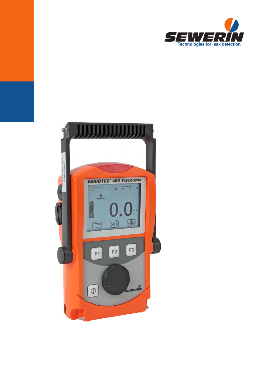
VARIOTEC® 460 Tracergas
20.04.2016 a – 106924 – en
Operating instructions
Page 2
VARIOTEC® 460 Tracergas
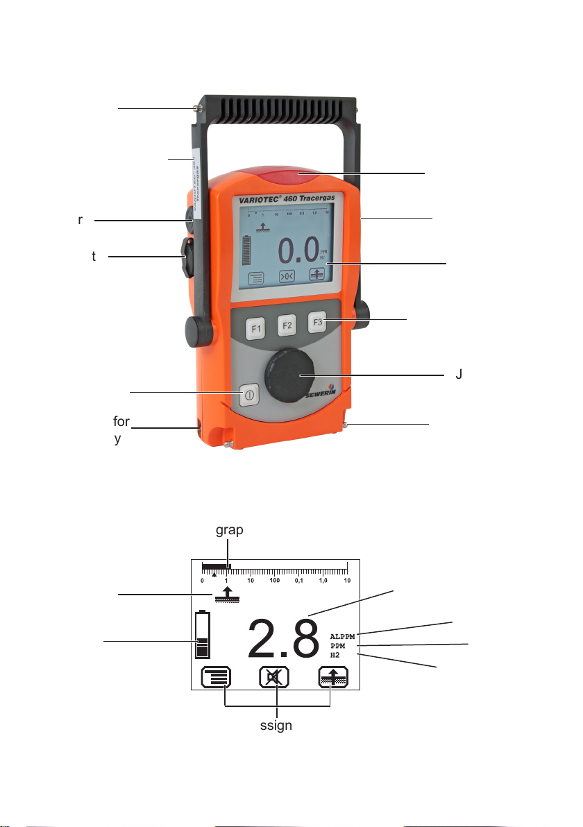
Connector
Supporting bracket
Signal light
Buzzer
USB port
ON/OFF key
Connection for
power supply
Fig. 1: VARIOTEC 460 Tracergas device overview
Bar graph
Selected
application
Battery
capacity
Gas input
Display
Function keys
Jog dial
Connector
Measured value
Alarm
Unit
Gas type
Current assignment of
function keys F1 – F3
Fig. 2: VARIOTEC 460 Tracergas display
Page 3
Esc
0
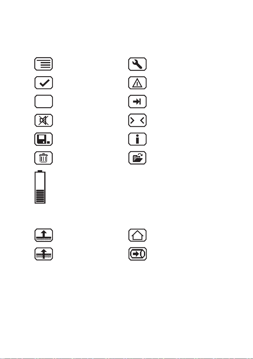
Display symbols
General
Menu Fault
OK Perform device inspection
Cancel Tab (jump to next input eld)
Buzzer off
Stop measurement Information
Clear
Battery capacity
Applications
Inspection above ground House
Measuring in bar holes Gas measuring
Set zero point
Open stored comments
Open stored inspectors
Page 4

Information about this document
The symbols used in the document mean the following:
NOTICE!
A
A
A
Indicates a hazardous situation for the product, which could
result in functional disturbance, damage or destruction.
CAUTION!
Indicates a hazardous situation for users, which could present
health risks or result in bodily injury.
WARNING!
Indicates a hazardous situation for users, which could result in
serious injury or death.
Note:
Indicates tips and useful information.
Instructions that must be followed in a specic sequence are numbered:
1. First action
2. Second action
a) Step one
b) Step two
Lists and instructions comprising only one action are indicated as follows:
● List point A
● List point B
− Subordinated list point
Page 5

Contents Page
1 General .....................................................................................1
1.1 Warranty ...................................................................................1
1.2 Purpose .....................................................................................2
1.3 Intended use .............................................................................3
1.4 General safety information ........................................................4
1.5 Allocation of tasks to applications .............................................5
1.6 Tracer gas method ....................................................................6
2 Features ...................................................................................7
2.1 Visual and audible signals .........................................................7
2.2 Sensors .....................................................................................8
2.3 Explosion protection .................................................................. 9
3 Operation ...............................................................................10
3.1 General information on operation ............................................ 10
3.1.1 Keys and jog dial .................................................................. 10
3.1.2 Selecting/exiting menus and menu items .............................10
3.1.3 Switching the device on ....................................................... 11
3.1.4 Selecting/switching applications ...........................................13
3.1.5 Differences between measuring mode and settings mode ..14
3.2 Measuring mode .....................................................................14
3.2.1 Accessing the menu (measuring mode menu structure) ......15
3.2.2 Zero point ............................................................................. 15
3.2.3 Inspection above ground ...................................................... 17
3.2.4 Measuring in bar holes ......................................................... 18
3.2.5 House ...................................................................................19
3.2.6 Gas measuring ..................................................................... 20
3.2.7 Settings ................................................................................21
3.2.8 Starting/stopping/saving a measurement ............................. 21
3.2.9 Protocols ..............................................................................24
3.2.10 Device inspection ................................................................. 24
3.2.11 Device information ...............................................................25
3.3 Settings ...................................................................................25
3.3.1 Opening settings ..................................................................25
3.3.2 Settings menu structure .......................................................27
3.3.3 Adjustment ...........................................................................28
3.3.4 System .................................................................................29
3.3.5 Alarms ..................................................................................30
3.3.6 Date/time .............................................................................. 30
3.3.7 Memory ................................................................................31
I
Page 6

Contents Page
4 Power supply .........................................................................32
4.1 Suitable disposable/rechargeable battery types .....................32
4.2 Operation with rechargeable batteries ....................................33
4.2.1 Charging ............................................................................... 33
4.2.2 Rechargeable battery maintenance .....................................34
4.3 Battery alarm ........................................................................... 35
4.4 Replacing disposable/rechargeable batteries .........................35
5 Maintenance ..........................................................................36
5.1 Device inspection ....................................................................36
5.1.1 General information on the device inspection ...................... 36
5.1.1.1 Scope ................................................................................ 36
5.1.1.2 Frequency .........................................................................36
5.1.1.3 Documentation .................................................................. 37
5.1.1.4 Integrated device inspection .............................................37
5.1.1.5 Order .................................................................................38
5.1.2 Performing the device inspection ......................................... 38
5.1.2.1 Accessing the device inspection ....................................... 38
5.1.2.2 Concluding the device inspection......................................39
5.1.3 Testing the general status ....................................................41
5.1.3.1 Housing ............................................................................. 41
5.1.3.2 Signals ..............................................................................41
5.1.3.3 Probe.................................................................................42
5.1.3.4 Filter ..................................................................................42
5.1.3.5 Pump .................................................................................42
5.1.4 Testing indication accuracy with supply of fresh air .............43
5.1.5 Testing indication accuracy with supply of test gas .............. 43
5.2 Adjustment ..............................................................................44
5.2.1 Scope ...................................................................................45
5.2.2 Suitable test gas concentrations ..........................................45
5.2.3 Preparation ........................................................................... 46
5.2.4 Performing the adjustment ................................................... 46
5.2.4.1 Adjusting the zero point.....................................................46
5.2.4.2 Adjusting the sensitivity ..................................................... 47
5.3 Servicing .................................................................................48
6 Faults ......................................................................................49
7 Appendix ................................................................................50
7.1 Specications and permitted operating conditions .................. 50
II
Page 7

Contents Page
7.2 Alarms .....................................................................................51
7.2.1 Features ...............................................................................51
7.2.2 Alarm thresholds (factory settings) .......................................52
7.3 Limit values for the device inspection .....................................52
7.4 Memory capacity .....................................................................53
7.5 Sensors ...................................................................................54
7.5.1 Gas-sensitive semiconductor (SC) for H2 ............................ 54
7.5.2 Thermal conductivity sensor (TC) for H2 .............................54
7.6 Technical information ..............................................................55
7.6.1 Sensitivity of the gas-sensitive semiconductor (SC) ............55
7.6.2 Electrostatic charge ..............................................................55
7.6.3 Identication sticker (back of device) ...................................55
7.6.4 Cleaning ............................................................................... 56
7.7 Accessories and consumables ................................................ 57
7.8 EU declaration of conformity ...................................................58
7.9 Inspection protocol ..................................................................59
7.10 Advice on disposal ..................................................................60
7.11 Terminology and abbreviations ...............................................61
7.12 Referenced documents ...........................................................61
8 Index .......................................................................................62
III
Page 8

1 General
1.1 Warranty
The following instructions must be complied with in order for any
warranty to be applicable regarding functionality and safe operation of this equipment. This product must only be commissioned
by qualied professionals who are familiar with the legal requirements (Germany: DVGW).
● Read these operating instructions prior to operating the product.
● Use the product only as intended.
● Repairs and maintenance must only be carried out by special-
ist technicians or other suitably trained personnel. Only spare
parts approved by Hermann Sewerin GmbH may be used when
performing repairs.
● Use only suitable battery types, otherwise the device will not
be explosion-proof.
● Changes or modications to this product may only be carried
out with the approval of Hermann Sewerin GmbH.
● Use only Hermann Sewerin GmbH accessories for the product.
Hermann Sewerin GmbH shall not be liable for damages resulting
from the non-observance of this information. The warranty con-
ditions of the General Terms and Conditions (AGB) of Hermann
Sewerin GmbH are not affected by this information.
In addition to the warnings and other information in these Operating Instructions, always observe the generally applicable safety
and accident prevention regulations.
The manufacturer reserves the right to make technical changes.
1 General
1
Page 9

1 General
1.2 Purpose
The VARIOTEC 460 Tracergas is a portable measuring device
for measuring the concentration of hydrogen in air or nitrogen.
The device is especially suitable for:
● Leak detection in pipes using hydrogen
Both gas and water pipes can be inspected. Water pipes must
not contain water at the time of inspection.
● Leak tests using the tracer gas method (e.g. in lling stations)
● Measuring the hydrogen content in air or nitrogen
All tasks that can be performed with the device are assigned to
applications. For more detailed information please see Section 1.5
on page 5.
WARNING!
A
The VARIOTEC 460 Tracergas is not a gas warning in-
strument.
● Do not use the device to warn against dangerous gas
concentrations.
Note:
These operating instructions describe the functions of rmware
version 1.XXX. The manufacturer reserves the right to make
changes.
All descriptions refer to the device as delivered (factory settings).
2
Page 10

1.3 Intended use
This device is intended for professional residential and commercial
use, in small rms and commercial operations and in industry. The
appropriate specialist knowledge is required to operate the device.
The device is intended for measuring hydrogen H2.
It should not be used for:
● Measuring toxic and corrosive gases
● Monitoring liquids
● Warning against explosive gas concentrations (operator pro-
tection)
The device can be used up to a temperature of 40 ºC. However,
high temperatures reduce the lifetime of the rechargeable batteries.
1 General
3
Page 11

1 General
1.4 General safety information
● The device has been tested to ensure that it is explosion-proof
in accordance with European standards (CENELEC).
● The device is explosion-proof for tracer gas only up to a maxi-
mum hydrogen content of 5% in air or nitrogen. If the hydrogen
content in air or nitrogen exceeds 5%, the device must be used
in carrying bag TG8.
● SEWERIN recommends always using the device in carrying
bag TG8 in enclosed spaces.
● Do not use this device in oxygen-enriched atmospheres, oth-
erwise it will not be explosion-proof.
● Only probe hoses with a hydrophobic lter may be used.
Exception:
If the probe has a built-in hydrophobic lter, the hose does not
require any other lters.
● Devices may only be tested with test gases in well ventilated
areas or outdoors. Test gases must be handled in a professional manner.
● Always carry out a device inspection (see Section 5.1 on
page 36) after the device has suffered an impact (for exam-
ple, if dropped accidentally).
● The device complies with the limits of the EMC directive. Always
observe the information in the manuals of (mobile) radio equipment when using the device close to (mobile) radio equipment.
NOTICE!
A
4
Follow the advice regarding explosion protection (see
Section 2.3 on page 9).
Page 12
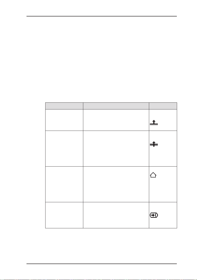
1.5 Allocation of tasks to applications
The device is used in measuring mode in four applications:
● Inspection above ground
● Measuring in bar holes
● House
● Gas measuring
Owing to the high sensitivity in the ppm range, the Inspection
above ground and House applications are particularly suitable
for leak detection but less so for reproducible measurements.
The table is designed to help you decide which application to
choose for which activity (in accordance with /1/).
Location Task Application
● Poorly accessible
gas pipes
– underground
– laid in oors
● In the ground ● Measuring the gas concentration
● In the house
● Freely accessible
pipes
● Industrial plants
● Test laboratories
● Pipes
● Gas systems
● Measuring very low gas concen-
trations:
– above ground or above the oor
– above possible leakage points
for:
– Determining gas dispersion
(detection limit)
– Locating a probable gas escape
(repair point)
– Preventing possible dangers
● Measuring very low gas concen-
trations
● Locating the source of gas
● Finding leaks at internal connec-
tions
● Leak testing of industrial compo-
nents
● Measuring the gas concentration
● Purging (to demonstrate purity or
absence of gas, e.g. when commissioning/decommissioning gas
systems)
1 General
Inspection
above ground
Measuring in
bar holes
House
Gas
measuring
5
Page 13

1 General
1.6 Tracer gas method
NOTICE!
A
The tracer gas method can be used for leak detection and for
leakage tests.
The method uses a nitrogen/hydrogen gas mixture (tracer gas)
consisting typically of 5% hydrogen and 95% nitrogen. Gas mixtures containing 10% hydrogen and 90% nitrogen can also be
used, however.
Owing to its physical properties, hydrogen has the ability to pen-
etrate other materials (e.g. screed, concrete). This penetrating
power is used to locate gas leaks in closed systems with a gas
measuring device such as the VARIOTEC 460 Tracergas.
Such closed systems may either already exist (e.g. lling stations)
or may have to be created. In the latter case the pipe sections
to be inspected are closed off with blind anges, for example.
Although pure hydrogen is extremely ammable, tracer gas is
non-combustible, non-corrosive and non-toxic. Hydrogen is ap-
proved as a food additive (E949), making the tracer gas method
suitable for inspecting water pipes.
This section provides only a brief overview of the tracer gas
method. Using the tracer gas method correctly requires
extensive specialist knowledge.
6
Page 14

2 Features
2.1 Visual and audible signals
The device features two alarms:
● Signal light on top of device (visual signal)
● Buzzer on side of device (audible signal)
If this symbol appears on the display, the audible
signal can be switched off.
When an audible signal has been switched off it
cannot be switched back on while the concentration
level remains above the alarm threshold.
This symbol appears at the top left of the display as
soon as the audible signal has been switched off. It
disappears automatically if the level falls below the
alarm threshold.
Alarm
If the measured hydrogen gas concentration exceeds specied
limit values (alarm thresholds) the device gives a warning. It emits
both audible and visual signals.
The device has two alarms:
● ALPPM (adjustable alarm in the ppm range)
● ALEOS (alarm at the end of the measuring range)
2 Features
Note:
Alarms are only emitted in the Inspection above ground and
House applications.
There are no alarms in the Measuring in bar holes and Gas
measuring applications.
The ALPPM alarm signal cycles between on and off. The ALEOS
alarm signal comprises a continuous tone and a steady light.
There is detailed information on alarms in Section 7.2 on
page 51.
7
Page 15

2 Features
Dynamic or constant signal for ALPPM
For the ALPPM alarm there are two options for cycling the audible and visual signals:
● dynamic (dynamic signal)
● constant
With the dynamic signal option the cycle speed is dependent on
the measured gas concentration. The higher the concentration
above the alarm threshold, the shorter the interval between two
signals. This applies up to a concentration of 5 % vol. H2. Above
a concentration of 5 % vol. H2 the cycle speed remains constant.
With the constant signal option the cycle speed is always independent of the measured gas concentration. The interval between
two signals is always constant.
The default setting at delivery is dynamic signal. If the dynamic
signal option is switched off, the device automatically switches
to a constant signal.
See Section 3.3.5 on page 30 for information on how to switch
off the dynamic signal.
2.2 Sensors
The device features two types of sensor:
● Gas-sensitive semiconductor (SC) for hydrogen
● Thermal conductivity sensor (TC)
Application Measuring range (H2) Sensors
Inspection above
ground
Measuring in bar holes 0.0 % vol. – 100 % vol. TC
House 0.0 ppm — 5 % vol. SC, TC
Gas measuring 0.0 % vol. – 100 % vol. TC
8
0.0 ppm — 5 % vol. SC, TC
Page 16

2.3 Explosion protection
The device is assigned to the following explosion-proof groups:
2 Features
Explosion-proof
group
II2G Ex d e ib IIB T4 Gb ● Methane CH
For the following atmospheres
● Propane C3H
● Butane C4H
4
8
10
When using
Device without carrying
bag TG8
● Tracer gas with max.
5% H2 in N2
II2G Ex d e ib IIC T4 Gb ● Methane CH
● Propane C3H
● Butane C4H
● Hydrogen H
4
8
10
2
Device with
carrying bag
TG8
● Tracer gas
EC type-examination certicate: TÜV 07 ATEX 553353 X
WARNING!
A
It is essential to observe the following points to ensure that
the device is explosion-proof:
● Only ever open the battery compartment and recharge
the batteries outside of explosive areas.
● Only use the USB port outside of explosive areas.
● Always use the appropriate type of disposable/recharge-
able battery.
● To ensure that the device complies with explosion-proof
group IIC with hydrogen H2 and tracer gas containing
more than 5% H2 in N2, the device must be used in carrying bag TG8.
9
Page 17

3 Operation
3 Operation
3.1 General information on operation
3.1.1 Keys and jog dial
The ON/OFF key is the only control on the device that does not
change its function.
When switched on, the device is operated using the jog dial and
function keys to navigate the display.
Control Action Function
ON/OFF key Press ● Switches the device on
● Switches the device off
Function keys
F1, F2, F3
Jog dial Turn ● Selects functions, settings,
Press ● Variable
● As indicated on the display at
the bottom of the screen
● Function keys may also have
no function assigned in some
cases
measurement data, etc.
● Modies values
Press ● Opens the next program level
(e.g. menu item, function,
measurement data, selectable
values)
● Applies values
3.1.2 Selecting/exiting menus and menu items
Functions, applications and settings etc. are selected via the main
menu (for short: Menu). This menu has submenus and menu
items. Refer to Section 3.2.1 on page 15 for information on
accessing the main menu.
10
Page 18

Selecting submenus/menu items
Submenus and menu items are selected and opened using the jog
dial and/or the function keys (see Section 3.1.1 on page 10).
The name of the selected menu or menu item is always shown
at the top left of the display.
In measuring mode the name of the selected application is in-
dicated by the symbol at the top left of the display. You can nd
detailed information on selecting and switching applications in
Section 3.1.4 on page 13.
Exiting menus/menu items
There are generally two ways to exit open menus/menu items
and return to the next level up:
● Press Esc
● Select Exit from the menu
3.1.3 Switching the device on
Note:
Always switch the device on with fresh air.
3 Operation
1. Press the ON/OFF key. The device switches on.
A visual and audible signal conrms that the device has been
switched on. The display and the pump come on.
The start screen appears on the display.
Display:
– Device type:
VARIOTEC 460 Tracergas
– User:
Frank Smith
City Council
Leakage Delivery
– Firmware version: V1.000
Fig. 3: Start screen
– Date and time
11
Page 19
3 Operation
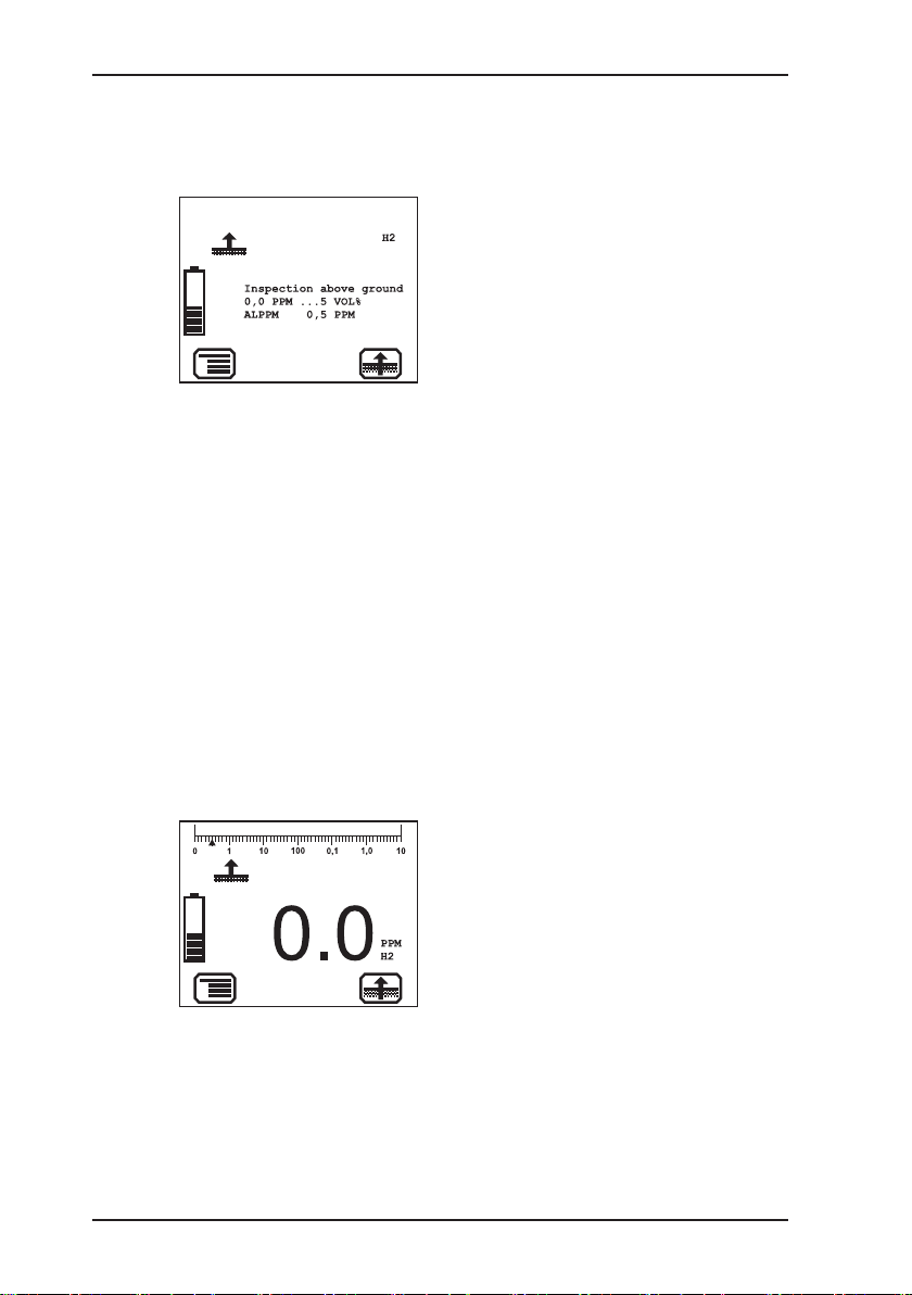
Fig. 4: Opening screen for In-
2. Make sure the device is actually drawing in fresh air. Change
3. Wait until the reading stops ashing.
Then the opening screen for the selected application appears
(see Section 3.3.4 on page 29).
Display:
– Gas type: H
2
– Application as symbol (top left)
and text:
Inspection above ground
– Measuring range:
0.0 ppm – 5 % vol.
– Alarm threshold:
spection above ground
application
ALPPM 0.5 ppm
– Symbol for next application that
can be selected via function
key F3: Measuring in bar holes
The device switches to measuring mode. The device warms
up. The reading ashes.
While the device is warming up, the prompt Add fresh air! is
displayed as a reminder.
its location if necessary.
The device is ready for use.
12
Display:
– Current reading: zero when
device is switched on with fresh
air
Fig. 5: Inspection above ground
measuring mode
Page 20

3.1.4 Selecting/switching applications
Note:
You may only switch applications when the device is drawing in
fresh air.
The current application is indicated by the symbol at the top left
of the display. The symbol at the bottom right shows the next application that can be selected via function key F3. You can specify
which application is activated rst when the device is switched on
in the Settings under System (see Section 3.3.4 on page 29).
● Press Menu. Select the menu item for the application you
want to use.
OR
a) Press function key F3. The device switches to the next ap-
plication.
b) Repeat until the symbol for the application you want to use
appears at the top left.
3 Operation
13
Page 21

3 Operation
3.1.5 Differences between measuring mode and settings mode
The device is operated in two modes:
● Measuring mode (see Section 3.2 on page 14)
Measurements are taken in measuring mode. All functions
needed to take readings can be accessed from one menu.
● Settings (see Section 3.3 on page 25)
The device settings can be changed in settings mode. Information about the device can also be retrieved. Measurements
cannot be taken in settings mode.
Settings are accessed via the menu in measuring mode. The
settings are access-protected by a PIN code.
CAUTION!
A
3.2 Measuring mode
When switched on (see Section 3.1.3 on page 11) the device
is in measuring mode. In measuring mode, the current measurements are always displayed (see Fig. 5). Depending on the ap-
plication, the measurement will have to be saved or started and
then stopped (see Section 3.2.8 on page 21).
The device only issues alarms in measuring mode. As
soon you access the menu, alarms are no longer triggered.
14
Page 22

3 Operation
Zero point
Exit
3.2.1 Accessing the menu (measuring mode menu structure)
In measuring mode F1 can be used to access the Menu.
Inspection above ground
Measuring in bar holes
House
Gas measuring
Settings
Start measurement
Protocol
Device inspection
Device information
Fig. 6: Menu with submenus (menu items)
Once you have started a measurement Start measurement in
the menu becomes Stop measurement. In some applications
this menu item is called Save measurement.
You can nd detailed information on starting, stopping and saving
measurements in Section 3.2.8 on page 21.
3.2.2 Zero point
The zero point only has to be set manually if the displayed fresh
air measurement is not zero after the end of the warm-up period.
The manual zero point setting is not saved. The zero point can be
corrected by adjustment as often as zero point deviations occur
(see Section 5.2 on page 44).
Requirements for correct setting of the zero point
● Device was switched on with fresh air.
● Device continues to draw in fresh air.
15
Page 23

3 Operation
Setting zero point (manual zero point setting)
1. Press Menu.
2. Select Zero point from the menu. The values are automatically
In the Inspection above ground and House applications the
Setting zero point function can also be opened by means of the
corresponding symbol.
adjusted. The device returns to measuring mode.
16
Page 24

3.2.3 Inspection above ground
Area of use
– Measuring very low gas concentrations in poorly accessible
gas pipes (underground or laid in oors)
– Measurement above ground, above the oor or above possi-
ble leakage points
Symbol
Unit
– ppm (parts per million)
– % vol.
Measuring range
3 Operation
Gas-sensitive
semiconductor
Thermal
conductivity sensor
Measurement data display
Fig. 7: Inspection above ground
measuring mode
0.0 to 10,000 ppm
0.1 to 5 % vol.
– Digits, e.g. 0.9 % vol. H
2
– Bar graph with quasi-logarith-
mic scale
17
Page 25

3 Operation
3.2.4 Measuring in bar holes
Area of use
– Measuring the gas concentration in the ground for:
– Determining gas dispersion (detection limit)
– Locating a probable gas escape (repair point)
– Preventing possible dangers
Symbol
Unit
– % vol.
Measuring range
Thermal
conductivity sensor
Measurement data display
Fig. 8: Measuring in bar holes
measuring mode
0.0 to 100 % vol.
– Digits, e.g. 0.6 % vol. H
2
– Bar graph with quasi-logarith-
mic scale
18
Page 26

3.2.5 House
Area of use
– Freely accessible pipes in buildings, industrial plants, test
laboratories
– Measuring very low gas concentrations
– Locating the source of gas
– Finding leaks at internal connections
– Leak testing of industrial components
Symbol
Unit
– ppm (parts per million)
– % vol.
Measuring range
3 Operation
Gas-sensitive
semiconductor
Thermal
conductivity sensor
Measurement data display
Fig. 9: House measuring mode
0.0 to 10,000 ppm
0.1 to 5 % vol.
– Digits, e.g. 0.2 ppm H
2
– Bar graph with quasi-logarith-
mic scale
19
Page 27

3 Operation
3.2.6 Gas measuring
Area of use
– Measuring the gas concentration in pipes and gas systems
– Purging (to demonstrate purity or absence of gas, e.g. when
commissioning/decommissioning gas systems)
Symbol
Unit
– % vol.
Measuring range
Thermal
conductivity sensor
Measurement data display
Fig. 10: Gas measuring mode
0.0 to 100 % vol.
– Digits, e.g. 30 % vol. H
2
– Bar graph with quasi-logarith-
mic scale
20
Page 28

3.2.7 Settings
You can change the device settings and access information
about the device under Settings in the menu (see Section 3.3
on page 25).
3.2.8 Starting/stopping/saving a measurement
Depending on the application, measurements will have to be
saved or started and then stopped.
3 Operation
Application
Inspection above
ground
start/stop save
Measurement
×
Measuring in bar holes ×
House ×
Gas measuring ×
Difference between starting/stopping and saving
Selecting Start measurement followed by Stop measurement
saves a measurement plot.
Selecting Save measurement saves an individual measurement,
the current one.
Note:
Measurements cannot be cancelled. The only way to cancel a
measurement is to stop it.
Up to 80 measurements can be saved.
The measured values can be saved with or without a comment.
Comment entries are saved automatically (ring memory with
max. 10 entries).
Once the rst comment has been entered, the Open
stored comments function will become available.
21
Page 29

3 Operation
The stored measurements can be displayed on a computer using a
readout program. The program is available at www.sewerin.com.
Start measurement
1. Press Menu.
2. Select Start measurement from the menu. This starts the
The measurement plot recording must always be concluded with
Stop measurement.
Stop measurement
1. Press Stop measurement.
2. Answer Yes to the warning prompt.
3. Enter a comment for the measurement.
measurement plot recording.
OR
a) Press Menu.
b) Select Stop measurement from the menu.
a) Select the characters required using the jog dial. Conrm
each character using the jog dial.
OR
− Press Open stored comments. A list of the stored com-
ments will appear. Select the desired comment. Open the
comment with OK.
b) Then conrm your entry/selection with OK.
OR
− Press Esc if you do not wish to enter a comment for the
measurement.
The measurement is saved as a protocol. The protocol name
is formed from the date, time and comment.
22
Page 30

3 Operation
Save measurement
1. Press Menu.
2. Select Save measurement from the menu.
3. Enter a comment for the measurement.
a) Select the characters required using the jog dial. Conrm
each character using the jog dial.
OR
− Press Open stored comments. A list of the stored com-
ments will appear. Select the desired comment. Open the
comment with OK.
b) Then conrm your entry/selection with OK.
OR
− Press Esc if you do not wish to enter a comment for the
measurement.
The measurement is saved as a protocol. The protocol name
is formed from the date, time and comment.
23
Page 31

3 Operation
3.2.9 Protocols
You can retrieve or clear protocols of saved data under Protocol
in the menu. When saved, the protocols are assigned to different
protocol types.
The following protocol types are available:
● Device inspection
● Measurements
Protocols can only be cleared individually.
You can nd information on how to clear all protocols of one pro-
tocol type in Section 3.3.7 on page 31.
3.2.10 Device inspection
The device inspection can be used to check the general status
and the indication accuracies. Device inspection only appears
in the menu when the integrated device inspection is switched on.
Note:
The integrated device inspection is switched off in the factory
settings. More detailed information about the device inspection
can be found in Section 5.1.2 on page 38.
24
The frequency of the device inspection depends on the application (see Section 5.1.1.2 on page 36).
If the integrated device inspection is switched on, the device will
remind you to perform a device inspection.
The Device inspection symbol will appear when the
inspection is due. It is visible in the display until the
complete integrated device inspection has been carried out successfully.
Page 32

3.2.11 Device information
The following device information is shown under Device information in the menu:
● Firmware:
version, date
● Service:
date of the last service, date of the next service
3.3 Settings
The following menus and menu items are included under Settings
(see Section 3.3.3 on page 28 to Section 3.3.7 on page 31):
● Adjustment
● System
● Alarms
● Date/time
● Memory
You can nd information on selecting and exiting menus and menu
items in Section 3.1.2 on page 10.
3 Operation
3.3.1 Opening settings
1. Press Menu.
CAUTION!
A
2. Select Settings from the menu.
The device only issues alarms in measuring mode. As
soon you access the menu, alarms are no longer triggered.
Access is protected by a PIN code. The default setting is
always PIN code 0001.
25
Page 33

3 Operation
Adjustment
Exit
Note:
You can change the PIN code at any time (see Section 3.3.4 on
page 29).
SEWERIN recommends setting a different PIN code after initial
start-up, so only authorised personnel have access to the settings.
3. Enter the PIN code from left to right. The active digit is always
displayed with a black background.
Digit To change To conrm
1st digit
Push the jog dial
2nd digit Push the jog dial
3rd digit Push the jog dial
Turn the jog dial
4th digit
If the PIN code has been entered correctly, the Settings menu
will appear once the last digit has been conrmed (Fig. 11).
Otherwise the device will revert to measuring mode.
26
System
Alarms
Date/time
Memory
Fig. 11: Settings menu
Page 34

3.3.2 Settings menu structure
PIN Code
Measurung mode
3 Operation
Settings Adjustment Adjustment H2 PPM
System PIN Code
Alarms
Date/Time
Memory Clear
Exit
Fig. 12: Menu structure for the VARIOTEC 460 Tracergas settings
Adjustment H2
Test gas
Inspection OK
Exit
Service interval
Display
Battery
Autostart
Device inspection
Reset
Language
Exit
Interval
Memory mode
Exit
27
Page 35

3 Operation
3.3.3 Adjustment
The Adjustment menu is used to set the sensors.
NOTICE!
A
Note:
A detailed description of adjustment along with important information is provided in Section 5.2 on page 44.
H2 PPM adjustment
Used to set the gas-sensitive semiconductor for hydrogen H2 in
the ppm range.
Applications: – Inspection above ground
The device may only be adjusted by specialist technicians
in well ventilated rooms or in the open air. Incorrect adjustment can lead to incorrect measurement results.
– House
28
H2 adjustment
Used to set the thermal conductivity sensor for hydrogen H2 in
the % vol. range.
Applications: – Inspection above ground
– Measuring in bar holes
– House
– Gas measuring
Test gas
Used to adjust the concentration of the test gases used.
Inspection OK
Conrms the device is in proper working order. This extends the
service interval.
Page 36

3.3.4 System
General information and specications for operation are set in
the System menu.
PIN code
Used to change or reset the PIN code.
Note:
If you lose the PIN code, you must contact SEWERIN Service.
If the PIN code is set to 0000, you will not be asked to enter it.
The settings can then be accessed by anyone.
Service interval
Species the regular inspections/maintenance required for the
device. You can also activate the automatic switch-off function
once the set interval has passed.
Display
Used to set how long the display remains illuminated after any
key is pressed as well as the display contrast.
3 Operation
Battery
Used to set the type of disposable/rechargeable battery used.
NOTICE!
A
Autostart
Sets the application that is automatically activated when the device is switched on.
The battery type setting must always be correct to prevent
damage to the device.
29
Page 37

3 Operation
Device inspection
Used to switch the integrated device inspection on or off.
Reset
Used to reset the device settings to the factory settings.
Language
Sets the language.
3.3.5 Alarms
Used to set the alarm threshold and the dynamic signal.
Note:
The ALEOS alarm cannot be adjusted. It always occurs at the
end of the measuring range.
There is detailed information on alarms in Section 7.2 on
page 51.
ALPPM
Sets the alarm threshold for exceeding signicant gas concentrations in the ppm range, which indicate a gas leak.
Application: – Inspection above ground
Dynamic signal
Switches the dynamic signal off or on.
See Section 2.1 on page 7 for detailed information on the
dynamic signal.
3.3.6 Date/time
Used to set the time, day, month and year. There are two formats
available for the date.
30
– House
Page 38

3.3.7 Memory
The Memory menu is used to specify how measurement data
and protocols are handled.
Clear
Used to clear protocols.
The different protocol types must each be cleared separately. All
protocols in one protocol type are cleared at once.
You can nd information on clearing individual protocols in Section 3.2.9 on page 24.
Interval
Set the interval at which measurement data is saved.
Memory mode
Switches between ring memory and stack memory.
3 Operation
31
Page 39

4 Power supply
4 Power supply
This device can be operated using:
● Disposable (non-rechargeable) alkaline batteries
● Rechargeable NiMH batteries
The device comes with nickel metal hydride rechargeable batteries. The corresponding settings are stored.
CAUTION!
A
4.1 Suitable disposable/rechargeable battery types
A
The device must not be used with leaking batteries.
● Replace leaking batteries.
● Clean the battery compartment (and, if necessary, the
device) before inserting the new disposable/rechargeable batteries.
WARNING!
To ensure that the device remains explosion-proof as per
/5/, only the following disposable/rechargeable batteries
may be used:
● Batteries supplied by SEWERIN
● Batteries other than those supplied by SEWERIN, pro-
vided compliance with /2/ is guaranteed.
The batteries used in a battery compartment must always
be identical in terms of type (disposable/rechargeable),
capacity and manufacturer.
32
Disposable battery requirements
● Alkaline disposable batteries
● Battery size: AA, Type: LR6 as per /3/
● The creepage distance and air gap between the poles must
not be less than 0.5 mm in accordance with /2/.
Page 40

Rechargeable battery requirements
● NiMH rechargeable batteries
● Battery size: AA, Type: HR6 as per /4/
● The creepage distance and air gap between the poles must
not be less than 0.5 mm in accordance with /2/.
● The rechargeable batteries must be fast charging (I > 1.25 A)
and remain within the temperature range.
NOTICE!
A
4.2 Operation with rechargeable batteries
The operating time of the device depends on the battery capacity.
If the device is not used or not kept in the docking station, the
batteries will lose their charge due to self-discharge. The selfdischarge intensity depends on the battery type.
A device operated with disposable alkaline batteries cannot
be charged. A note to this effect is shown on the display.
4 Power supply
4.2.1 Charging
The device can be charged via:
● Connection for power supply
● Docking station TG8
WARNING!
A
For charging you will need either:
Please note the following points:
The device must only be charged outside of explosive
areas.
● M4 AC/DC adapter
● M4 vehicle cable
33
Page 41

4 Power supply
● The device or docking station must not be directly connected
to a 24-V on-board power supply in the vehicle. The voltage is
too high for the charging process.
● The battery should be charged at approximately room tem-
perature.
4.2.2 Rechargeable battery maintenance
If the device is not used for a long period of time, it is advisable
to fully discharge the battery before recharging it again.
A full discharging and recharging process takes approx. 11 hours
(8 hours to discharge + 3 hours to recharge). The duration depends on the capacity of the rechargeable batteries used.
WARNING!
A
The device must only be charged outside of explosive
areas.
● Connect the device (switched on) to the power supply via the
side connection.
OR
− Place the device (switched on) into the docking station.
The rechargeable batteries will be fully discharged. Once the
device has been discharged, it will automatically switch to
charging mode.
34
Page 42

4.3 Battery alarm
As soon as the remaining capacity of the batteries gets low, a
battery alarm will go off:
Level 1: Battery almost empty
– Battery capacity symbol ashes
– Audible signal (one-off)
– Operating signal doubles
– Remaining operating time: approx. 15 min
Level 2: Battery empty
– Blank display apart from Battery capacity symbol
– Continuous audible signal
– Measuring mode unavailable
– Device shuts off
4.4 Replacing disposable/rechargeable batteries
WARNING!
A
The battery compartment must only be opened outside
of explosive areas.
4 Power supply
A 2.5 mm Allen key (supplied) is required to open the battery
compartment on the back of the device.
1. Loosen the two screws securing the battery compartment. Remove the screws by repeatedly turning them alternately a short
way; this ensures that the battery compartment does not twist.
2. Lift out the battery compartment.
3. Remove the disposable/rechargeable batteries and insert new
ones. Ensure that the batteries are inserted with the correct
polarity.
4. Replace the battery compartment so it ts neatly into place
and secure rmly with the screws.
5. When you switch the device back on again, you will be asked
which battery type is in use. Enter the correct battery type.
If it takes longer than 120 seconds to replace the batteries, the
date and time will have to be reset the next time you switch the
device on. All the other data will be saved.
35
Page 43

5 Maintenance
5 Maintenance
In accordance with the legal regulations, device maintenance
comprises the following elements:
● Device inspection including test of indication accuracy
● Adjustment
● Servicing
All inspections must be documented. The documentation must
be retained for at least one year.
5.1 Device inspection
5.1.1 General information on the device inspection
5.1.1.1 Scope
The device inspection includes the following tests:
● Analysis of the general status (see Section 5.1.3 on page 41)
● Test of the indication accuracy with supply of fresh air (see
Section 5.1.4)
● Test of the indication accuracy with supply of test gas (see
Section 5.1.5)
5.1.1.2 Frequency
The frequency of the device inspection depends on the application.
Application When to test
Inspection above ground weekly
Measuring in bar holes every 3 months
House weekly
Gas measuring every 3 months
36
This symbol appears in the display when a device
inspection is due for the selected application.
Page 44

The applications are grouped together for the device inspection.
The device inspection must be performed separately for each
group.
5.1.1.3 Documentation
The device inspection procedure must be documented. There
are two ways of doing this:
● On paper
● Saved electronically supported by the device (integrated de-
vice inspection)
Only the integrated device inspection is described in these operating instructions.
Note:
The device inspection must be documented on paper if the integrated device inspection is switched off.
5.1.1.4 Integrated device inspection
The integrated device inspection is accessed via the menu
(Fig. 6).
The results of the device inspection are stored in the device as
a protocol.
The device inspection protocols can be opened in the device at
any time (see Section 3.2.9 on page 24). They can also be
displayed on a computer using a readout program.
The program is available at www.sewerin.com.
5 Maintenance
The Perform device inspection symbol appears when
a device inspection is due. It is visible in the display until
the complete integrated device inspection has been carried out successfully for the selected application. If the
device inspection was completed but the device failed
on some points (not OK), the symbol will remain visible.
The integrated device inspection is switched off in the factory
settings. The integrated device inspection has to be switched on
(once only) before it can be performed.
37
Page 45

5 Maintenance
Inspection above ground/houses
Bar holes/measuring
Switching on the integrated device inspection
1. Press Menu.
2. Select Settings.
3. Enter your PIN code .
4. Select System.
5. Select Device inspection.
6. Select Yes.
7. Apply the setting with OK.
8. Exit the settings with Exit.
5.1.1.5 Order
You can carry out the device inspections and the associated
tests for the applications (groups) that are due to be inspected
in any order you wish. You can repeat the tests as often as you
wish provided you have not yet concluded the device inspection
for a group.
5.1.2 Performing the device inspection
5.1.2.1 Accessing the device inspection
The device is in measuring mode.
1. Press Device inspection.
OR
a) Press Menu.
b) Select Device inspection from the menu.
The Device inspection menu appears.
Fig. 13: Device inspection menu
All the applications (groups) for which a device inspection is
required are listed under Required.
2. Selecting an application (group).
38
Page 46

The Dev. Test ... menu appears.
3. Select a test from the menu (General status, Fresh air, Test
gas H2).
4. Carry out the test.
For detailed information, refer to the following sections:
− General status Section 5.1.3
− Fresh air Section 5.1.4
− Test gas … Section 5.1.5
5.1.2.2 Concluding the device inspection
After all the tests have been carried out as described in Section 5.1.3 to Section 5.1.5, the Save symbol will appear in the
display.
An integrated device inspection is concluded by saving it. Up to
40 device inspections can be saved. The following information
can be stored along with the device inspection:
● Inspector (e.g. inspector's name or initials)
● Password to protect the protocol from being accessed by un-
authorised people
Inspector entries are saved automatically (ring memory with max.
10 entries).
5 Maintenance
Once the rst inspector has been entered, the Open
stored inspectors function will become available.
1. Press Save.
2. Enter the name of the inspector.
a) Select the characters required using the jog dial. Conrm
each character using the jog dial.
OR
− Press Open stored inspectors. A list of the stored in-
spectors will appear. Select the desired inspector. Open
the inspector with OK.
b) Then conrm your entry/selection with OK.
OR
39
Page 47

5 Maintenance
3. Enter a password.
4. Conrm the overview by pressing OK. The device returns to
− Press Esc if you do not wish to enter an inspector for the
device inspection.
a) Select the characters required using the jog dial. Conrm
each character using the jog dial.
b) Then conrm your entry with OK.
OR
− Press Esc if you do not wish to enter a password for the
device inspection.
The device inspection is saved as a protocol. An overview with
the device inspection results is displayed.
This overview includes a list of all gas types for which the
device is congured. Gas types for which the indication accuracy was successfully tested in the device inspection are
agged with OK. Gas types that are available but have not
been tested are agged with ----.
measuring mode.
40
Page 48

5.1.3 Testing the general status
The general status test is part of the device inspection (see Section 5.1.1.1). It is based on estimations by the user. The following
must be tested:
● Housing
● Signals
● Probe
● Filter
● Pump
The battery charge status and the working condition of the controls
are automatically tested during the integrated device inspection.
The device inspection has been opened (see Section 5.1.2.1).
1. Select General status from the Dev. Test ... menu.
2. Test all associated subitems as described in Section 5.1.3.1
to Section 5.1.3.5.
3. Conrm the prompt General status OK? by pressing Yes if
all subitems show no faults during testing. General status
OK appears on the display.
5 Maintenance
5.1.3.1 Housing
● Is the housing free from external damage?
5.1.3.2 Signals
During the integrated device inspection the signals are emitted
at short intervals.
● Can the audible signal be heard?
● Is the visual signal visible?
41
Page 49

5 Maintenance
5.1.3.3 Probe
Probes are accessories. They only need to be tested if they are
likely to be used in the course of the working day.
● Are the probes free from external damage?
Probe hoses are tested with a simple leak check.
1. Connect the probe hose to the gas input.
2. Seal the free end of the probe hose.
An error message should appear after approx. 10 seconds.
This indicates that the probe hose is in good condition.
5.1.3.4 Filter
The ne dust lter is located behind the gas input. It is tested by
means of a visual inspection.
1. Unscrew the gas input.
2. Remove the ne dust lter.
3. Check that there is no dirt in the ne dust lter.
As soon as there are any signs of deposits, the lter must be
replaced. If you do not replace the lter, you must reinsert it
exactly as you found it.
5.1.3.5 Pump
The pump function is tested with a simple leak check.
1. Seal the gas input.
After a maximum of 10 seconds an error message should appear. This indicates that the pump is working correctly.
If the error message does not appear, the pump may be faulty.
The device must be tested by SEWERIN Service.
2. Release the gas input again.
After approximately 5 seconds, the error message should
disappear again. Otherwise there is a fault (see Section 6).
42
Page 50

5 Maintenance
5.1.4 Testing indication accuracy with supply of fresh air
The indication accuracy with supply of fresh air test is part of the
device inspection (see Section 5.1.1.1).
The device inspection has been opened (see Section 5.1.2.1).
1. Make sure that only fresh air is being drawn in.
2. Select Fresh air from the Dev. Test ... menu.
3. Wait until the displayed reading is stable. A Status: OK message will appear.
4. Press OK to conrm. Fresh air OK will appear on the display.
If the Status: OK message does not appear within a reasonable
amount of time, the air inow does not correspond to the limit
values stored in the device (see Section 7.3 on page 52). Move
the device somewhere else and repeat the test.
If the Status: OK message still does not appear when the test
is repeated, the device must be re-adjusted (see Section 5.2).
5.1.5 Testing indication accuracy with supply of test gas
The indication accuracy with supply of test gas test is part of the
device inspection (see Section 5.1.1.1).
The following resources are needed for the test:
● Test gas containing hydrogen (e.g. 5% H2 in 95% N2)
● Test set for the supply of test gas
Note:
Details of how to use the test set can be found in the accompanying operating instructions.
The device inspection has been opened (see Section 5.1.2.1).
1. Select Test gas H2 from the Dev. Test ... menu.
2. Check whether the test gas concentration specied by the
device matches the test gas you intend to use. To do this
press Information.
3. Add the test gas
43
Page 51

5 Maintenance
4. Wait until the displayed reading is stable. A Status: OK mes-
5. Press OK to conrm.
6. Stop the test gas supply.
If the Status: OK message does not appear within a reasonable
amount of time, this may be due to the following:
Cause Corrective action
Connections leaking Repeat check, checking the
Measurement values outside
the specied limit values
(see Section 7.3)
Changing the test gas concentration
If no test gas with the specied concentrations is available for
the test, the values can be changed according to the test gas
used under Test gas in the adjustment menu (see section Sec-
tion 3.3.3 on page 28).
sage will appear.
seal on the connections
Adjustment required
(see Section 5.2)
5.2 Adjustment
NOTICE!
A
44
The device may only be adjusted by specialist technicians
in well ventilated rooms or in the open air. Incorrect adjustment can lead to incorrect measurement results.
Page 52

5.2.1 Scope
Adjustments must be made separately for each measuring range.
● Zero point
● Sensitivity
NOTICE!
A
5.2.2 Suitable test gas concentrations
The following test gas concentrations can be used for adjustment:
For each measuring range always adjust the zero point
rst, followed by the sensitivity.
Zero point Measuring range sensitivity
H2 PPM adjustment H2 adjustment
Fresh air H2 in synthetic air
● 1 ppm
● 10 ppm
● 100 ppm
● 1000 ppm
● 1.00 % vol.
5 Maintenance
H2 in N
2
● 5 – 100 % vol.
It is not necessary to use all test gas concentrations to adjust a
measuring range. However, adjusting with more than one test gas
concentration increases the measurement quality.
SEWERIN recommends the following test gas concentrations for
adjusting the sensitivity:
● H2 PPM adjustment: 100 ppm H2 in synthetic air
● H2 adjustment: 5 % vol. H2 in N
2
45
Page 53

5 Maintenance
5.2.3 Preparation
Carrying out an adjustment always takes some time. Leave yourself plenty of time to prepare the necessary steps of the procedure.
Have all necessary tools available. Let the device run for several
minutes to ensure that the temperature is correct, for example.
5.2.4 Performing the adjustment
The zero point and sensitivity are adjusted following the same
procedure for all gas concentrations (see Section 5.2.4.1 on
page 46 / Section 5.2.4.2 on page 47).
You can nd detailed information on adjustment (for
example, test gas concentration, installation date of
the sensor, date of last adjustment) under Information.
The symbol appears after the corresponding Adjust-
ment… menu item has been selected.
5.2.4.1 Adjusting the zero point
The zero point is adjusted following the same procedure for all
gas concentrations.
1. Make sure that only fresh air is being drawn in.
2. Open the settings (see Section 3.3.1 on page 25).
3. Select Adjustment from the menu.
4. Select the desired adjustment (e.g. H2 PPM adjustment).
5. Wait at least 1 minute. The displayed reading must be stable.
6. Select Zero point from the menu (select and conrm with OK).
This adjusts the zero point. The reading shows zero (0.0 %
vol. or 0.0 ppm).
46
Page 54

5.2.4.2 Adjusting the sensitivity
The sensitivity is adjusted following the same procedure for all
gas concentrations.
The following resources are needed for adjusting the sensitivity:
● Test gas (see Section 5.2.2 on page 45)
● Test set for the supply of test gas
Note:
Details of how to use the test set can be found in the accompanying operating instructions.
1. Connect the device to the test set.
2. Open the settings (see Section 3.3.1 on page 25).
3. Select Adjustment from the menu.
4. Select the desired adjustment (e.g. H2 PPM adjustment).
5. Select the menu item that species the sensitivity to be tested
(for example100 PPM H2). Do not conrm with OK yet.
6. Press and hold the release button on the test set. The test gas
is added. Do not let go of the release button.
7. Wait at least 1 minute. The displayed reading must be stable.
8. Press OK to conrm. The device is adjusted. The reading
shows the specied value (e.g. 100 ppm H2).
9. Let go of the release button on the test set.
5 Maintenance
47
Page 55

5 Maintenance
5.3 Servicing
The device must only be serviced and repaired by SEWERIN
Service.
● Send the device to SEWERIN for repairs and for annual main-
tenance.
Note:
If there is a service agreement in place, the device can be serviced by the mobile maintenance service.
Fig. 14: Inspection plate
The inspection plate on the device shows con-
rmation of the last maintenance and the next
scheduled maintenance.
48
Page 56

6 Faults
If a fault occurs during operation, an error message will appear
on the screen.
Error messages are displayed in the order in which they occur.
Up to ve errors can be displayed. Error messages continue to
be displayed until the error is corrected.
Overview of possible error messages
6 Faults
Error
code
8 No calibration
10 Adjustment failed
52 XFLASH
59 Error unknown
60 PX sensor Error can only be corrected by
100 Pump error
202 I2C HOST – EX
Error message on the
display
PPM sensor adjustment
Test gas
SEWERIN Service
SEWERIN Service
Probe/lter
SEWERIN Service
Error correction
H2 ppm adjustment required
(see Section 5.2 on page 44)
Check test gas
(see Section 5.2 on page 44)
Error can only be corrected by
SEWERIN Service
Error can only be corrected by
SEWERIN Service
SEWERIN Service
Check all lters, probes and hose
connections for porosity and dirt
Error can only be corrected by
SEWERIN Service
49
Page 57

7 Appendix
7 Appendix
7.1 Specications and permitted operating conditions
Device data
Dimensions (W x D x H) approx. 148 x 57 x 205 mm
approx. 148 x 57 x 253 mm with supporting
bracket
Weight approx. 1000 g, depending on equipment
Device elements
Display Monochromatic graphic display, 320 x 240 pixels
Buzzer Frequency 2.4 kHz, volume 80 db (A) / 1 m
Signal light Red
Pump capacity Vacuum > 250 mbar
Volume ow approx. 50 l/h
Interface USB
Memory 8 MB
Operation ON/OFF key, 3 function keys, jog dial
50
Operating conditions
Operating temperature -20 °C – +40 °C
Storage temperature -25 °C – +60 °C (temperatures above 40 °C re-
duce the lifetime of the rechargeable batteries)
Humidity 5–90 % r.h., non-condensing
Atmospheric pressure 800 – 1100 hPa
Protection rating IP54
Power supply
Power supply 4 AA cells, either:
NiMH rechargeable or disposable alkaline batteries
Operating time, typical At least 8 h
Charging time approx. 3h (complete charge) depending on
capacity
Charging voltage 12 V DC, max. 1 A
Page 58

7.2 Alarms
Note:
Alarms are only emitted in the Inspection above ground and
House applications.
There are no alarms in the Measuring in bar holes and Gas
measuring applications.
7.2.1 Features
ALEOS
Type: End of measuring range
Adjustable: No
Latching: No
Trigger: ALEOS alarm threshold exceeded
Indicator: – Audible signal
Acknowledgement:
Reset: – Automatic when level falls below ALEOS alarm
7 Appendix
– Visual signal
– ALEOS notication on display
– Reading ashes
– Not possible
threshold
– By switching device off
ALPPM
Type: Warning of gas concentration in ppm range
Adjustable: Yes
Latching: No
Trigger: ALPPM alarm threshold exceeded
Indicator: – Audible signal
– Visual signal
– ALPPM notication on display
Acknowledgement:
Reset: – Automatic when level falls below ALPPM alarm
– Possible for audible signal when ALPPM alarm
threshold is exceeded
threshold
51
Page 59

7 Appendix
7.2.2 Alarm thresholds (factory settings)
Application ALEOS ALPPM
Inspection above ground 5 % vol. 0.5 ppm
Measuring in bar holes 100 % vol. —
House 5 % vol. 0.5 ppm
Gas measuring 100 % vol. —
7.3 Limit values for the device inspection
Application Gas Zero point Sensitivity
Inspection above
ground/House
Gas measuring/
Measuring in bar
holes
Specication
H20.0 ppm ±0.5 ppm 100 ppm +100 ppm
H20.0 % vol. ±1 % vol. 5 % vol. ±1 % vol.
Deviation Specica-
tion
Deviation
-90 ppm
52
Page 60

7.4 Memory capacity
The total memory capacity of the device is divided up as follows:
Protocol type Maximum number of storable protocols
Device inspection 40
Measurement 80
There is a choice of two memory modes (see Section 3.3.7 on
page 31). The selected memory mode applies for all protocol
types.
Measurements
Note:
A le is saved after each Start measurement – Stop meas-
urement cycle, regardless of whether the memory capacity is
exhausted.
Each le has a maximum memory capacity of 1800 data records.
This means that a le can record data for 30 min (0.5 h) at a save
interval of 1 second. After this, data recording continues automati-
cally in the next le.
7 Appendix
Save
interval
1 s 0.5 h 40 h
2 s 1 h 80 h
5 s 2.5 h 200 h
10 s 5 h 400 h
20 s 10 h 800 h
Factory settings in bold
Save time for 1 le
(1800 data records)
Save time for 80 les
(max. memory capacity)
53
Page 61

7 Appendix
7.5 Sensors
Note:
Probes increase the stated response times.
7.5.1 Gas-sensitive semiconductor (SC) for H2
Measuring range 0.0 – 10000 ppm (1 % vol.)
Resolution 1 ppm / 2 ppm / 20 ppm / 200 ppm
Response times 10 ppm H2:
tR < 1.2 s t50 < 6 s t90 < 18 s
100 ppm H2:
tR < 1.0 s t50 < 7 s t90 < 15 s
tR … Time until device’s rst response following
delivery of gas
Warm-up times up to 5 min
Measuring error 30 % (short time)
Interference at 20 ºC:
1 % vol. CH4 50 ppm maximum
1 % vol. C3H8 10 ppm maximum
40 ppm CO 2 ppm maximum
1 % vol. C2H6O (ethanol) 2 ppm maximum
3500 ppm benzene 10 ppm maximum
Water vapour, < 80% r.h. < 1 ppm typical
Lifetime, expected 5 years
7.5.2 Thermal conductivity sensor (TC) for H2
Measuring range 0 – 100 % vol.
Resolution 0.1 % vol.
Response times
Warm-up time < 30 s
Measuring error 3 % of measuring range end value
Interference to all gases with a different thermal conductivity
Lifetime, expected 5 years
54
t50 < 3.1 s t90 < 6.5 s
Page 62

7 Appendix
7.6 Technical information
7.6.1 Sensitivity of the gas-sensitive semiconductor (SC)
Low-oxygen atmospheres can reduce the sensitivity of the gas-
sensitive semiconductor (sensor suffocation).
Gaseous constituents of silicones, oils and phosphate esters for
example have a damaging effect on the sensor. They permanently
reduce the sensitivity.
Contamination of the measurement environment with halogens,
burnt neoprene, PVC or trichloroethene for example also lowers
the sensitivity of the sensors, but they can be regenerated.
7.6.2 Electrostatic charge
Avoid electrostatically charging the device. Electrostatically unearthed objects (e.g. including metallic housing without an earth
connection) are not protected against applied charges (e.g.
through dust or dispersed ows).
NOTICE!
A
To prevent electrostatic charging when working with hydrogen H2, always use the carrying bag TG8.
7.6.3 Identication sticker (back of device)
The symbols on the sticker mean the following:
Only ever open the battery compartment outside of
explosive areas.
Read the operating instructions.
55
Page 63

7 Appendix
7.6.4 Cleaning
The device must only be cleaned with a damp cloth.
NOTICE!
A
Do not use solvents, petrol or cockpit spray containing
silicone or similar substances to clean the device!
56
Page 64

7.7 Accessories and consumables
Accessories
Part Order number
Docking station TG8 LP11-10001
M4 AC/DC adapter LD10-10001
M4 vehicle cable, 12 V= mobile ZL07-10100
M4 vehicle cable, 12 V= mounting ZL07-10000
M4 vehicle cable, 24 V= mobile ZL09-10000
Carrying system “Vario” 3209-0012
Carrying bag TG8 3204-0040
Case TG8-RÜ ZD29-10000
Compact case TG8 ZD31-10000
Carpet probe PRO ZS01-12000
Bell probe D125 ZS05-10300
Localisation probe 345 mm ZS03-10300
Flexible hand probe ZS32-10000
Probe hose ZS25-10000 (e.g.)
Test gas generator PGG H2 VT10-Z1000
Test set SPE VOL PP01-90101
Test set SPE ppm PP01-40101
Test set SPE DUO PP01-60001
Test plate ZP06-10000
7 Appendix
Consumables
Part Order number
Fine dust lter 2499-0020
Hydrophobic lter 2491-0050
Special lter element 2499-0005
Rechargeable NiMH battery 1354-0009
Disposable alkaline battery 1353-0001
Test gas 100 ppm H2 in synthetic air, test gas can
1 l, pressure approx. 12 bar
Test gas 5.0 % vol. H2 in N2, test gas can 1 l,
pressure approx. 12 bar
ZT18-10000
ZT37-10001
Other accessories and consumables are available for the product. Please contact our SEWERIN sales department for further
information.
57
Page 65

7 Appendix
7.8 EU declaration of conformity
Hermann Sewerin GmbH hereby declares that the
VARIOTEC® 460 Tracergas fulls the requirements of the fol-
lowing guidelines:
● 2014/30/EU
● 2014/34/EU
Gütersloh, 2016-04-20
Dr S. Sewerin (General Manager)
The complete declaration of conformity can be found online.
58
Page 66

7.9 Inspection protocol
Variotec
®
460 Tracergas
– Disposable/rechargeable battery
capacity (e.g.: ¼)
Gas-sensitive semiconductor (Inspection above ground/House)
Test gas 100 ppm H2 (in synthetic air)
Thermal conductivity sensor (Measuring in bar holes/Gas measuring)
Test gas 5 % vol. H2 (in N2)
Rapid test with PGG H2 (Inspection above ground/House)
7 Appendix
INSPECTION PROTOCOL
Serial no. (e.g.: 065 15 00480)
1.0 General status
1.1 – Perfect condition (e.g.: Y / N)
1.2 – Fine dust filter correct (e.g.: Y / N)
1.3
2.0 Pump check
2.1 – Pump error F100 in seal
3.0
3.1 Zero point
– Display with fresh air
3.2
– Display 70 – 150 % vol.
4.0
4.1 Zero point
– Display -1.0 – +1.0 % vol.
4.2
– Display 3.0 – 7.0 % vol.
5.0
5.1 Zero point
– Display with fresh air
5.2 Test gas H2 (from PGG H2)
– Display >1.5 ppm; 8.0 ppm typical
6.0 Comments
– Housing damaged
– Adjustment, repair
– Inspection at factory
– or similar
7.0 Inspection
– Day
– Month
– Year
– Signature
02.05.2012
- 1 -
59
Page 67

7 Appendix
7.10 Advice on disposal
The European Waste Catalogue (EWC) governs the disposal of
appliances and accessories.
Description of waste Allocated EWC waste code
Device 16 02 13
Test gas can 16 05 05
Disposable battery,
16 06 05
rechargeable battery
End-of-life equipment
Used equipment can be returned to Hermann Sewerin GmbH.
We will arrange for the equipment to be disposed of appropriately
by certied specialist contractors free of charge.
60
Page 68

7.11 Terminology and abbreviations
ALEOS ● Alarm at end of measuring range (end of
scale)
ALPPM ● Adjustable alarm in ppm range
CENELEC ● European Committee for Electrotechnical
Standardization
NiMH ● Nickel metal hydride
ppm ● Parts per million
Ring memory ● Type of data storage in the device
● If the available storage space is full, the
oldest le is automatically overwritten by
the current le.
SC ● Gas-sensitive semiconductor
Stack memory ● Type of data storage in the device
● If the available storage space is full, you
are prompted to conrm whether the oldest le should be overwritten by the current le.
TC ● Thermal conductivity sensor
VOL ● Volume
7 Appendix
7.12 Referenced documents
The following standards, guidelines and regulations are referred
to in these operating instructions:
/1/ DVGW G 465-4
Deutsche Vereinigung des Gas- und Wasserfaches e. V. (German
Association of Gas and Water Specialists); Regulation G 465-4:
Gasspür- und Gaskonzentrationsmessgeräte für die Überprüfung
von Gasanlagen (Gas-Detection and Gas-Concentration Measurement Devices for Inspection of Gas Systems)
Available for download at: www.dvgw.de
/2/ EN 60079-7:2007
/3/ EN 60086-1
/4/ EN 61951-2
/5/ 94/9/EC (ATEX 100a)
61
Page 69

8 Index
8 Index
A
Accessories 57
Adjustment 28, 44
H2 28
H2 ppm 28
Performing 46
Preparation 46
Scope 45
Sensitivity 47
Zero point 46
Adjustment menu 28
Alarm 7, 30, 51
Alarm thresholds 52
Application
Associated task 5
Selecting 13
Switching 13
Autostart 29
B
Battery alarm 35
C
Cleaning 56
Clearing 31
Comment 21
Constant signal 8
Consumables 57
D
Date 30
Device
Switching off 10
Switching on 10
Device information 25
Device inspection 24, 30, 36
Accessing 38
Concluding 39
Documentation 37
Frequency 36
Integrated 37
Limits 52
Order 38
Performing 38
Scope 36
Switching on 38
Display 29
Display contrast 29
Display illumination 29
Disposable battery 29
Replacing 35
Requirements 32
Setting the type 29
Suitable types 32
Disposal 60
Dynamic signal 8, 30
E
Electrostatic charge 55
Error message 49
Explosion protection 9
F
Factory settings 30
Faults 49
Filter 42
Fine dust lter 42
Function key 10
G
Gas measuring 20
Gas-sensitive semiconductor see Sen-
sor
General status 41
H
House 19
Housing 41
I
Identication plate 55
Indication accuracy
With fresh air 43
With test gas 43
Inspection above ground 17
Inspection OK 28
Inspection protocol 59
Inspector 39
62
Page 70

8 Index
Integrated device inspection see Device
inspection
Interval 31
J
Jog dial 10
K
Keys 10
L
Language 30
M
Main menu see Menu
Maintenance 36
Manual zero point setting see Setting
zero point
Measurement
Protocol 22, 23
Read protocol 22
Saving 21, 23
Starting 21, 22
Stopping 21, 22
Measuring in bar holes 18
Measuring mode 14
Menu structure 15
Memory 31, 53
Memory mode 31
Menu 10, 15
Exiting 11
Opening 15
Selecting 11
Menu item
Exiting 11
Selecting 11
Menu structure 15, 27
O
Open stored comments 21
Open stored inspectors 39
Operation 10
P
Password 39
PIN code 25, 29
Power supply 32
Probe 42
Protocol 24
Reading 37
Protocol types 24
Pump 42
R
Readout program 22, 37
Rechargeable battery 33
Charging 33
Maintenance 34
Replacing 35
Requirements 33
Self-discharge 33
Setting the type 29
Suitable types 32
Ring memory 31
S
Sensitivity
Adjusting 47
Sensor 8, 54
Gas-sensitive semiconductor 8, 54
Thermal conductivity 8, 54
Service interval 29
Servicing 48
Settings 14, 21, 25
Menu structure 27
Opening 25
Signals 41
Audible 7
Constant 8
Dynamic 8
Visual 7
Stack memory 31
System 29
T
Test gas 28
Changing 44
Suitable 45
63
Page 71

8 Index
Thermal conductivity see Sensor
Time 30
U
Use
Intended 3
Z
Zero point 15
Adjusting 16, 46
64
Page 72

Hermann Sewerin GmbH
Robert-Bosch-Straße 3
33334 Gütersloh, Germany
Tel.: +49 5241 934-0
Fax: +49 5241 934-444
www.sewerin.com
info@sewerin.com
SEWERIN SARL
17, rue Ampère – BP 211
67727 Hoerdt Cedex, France
Tél. : +33 3 88 68 15 15
Fax : +33 3 88 68 11 77
www.sewerin.fr
sewerin@sewerin.fr
SEWERIN IBERIA S.L.
Centro de Negocios “Eisenhower”
Avenida Sur del Aeropuerto
de Barajas 28, Of. 2.1 y 2.2
28042 Madrid, España
Tel.: +34 91 74807-57
Fax: +34 91 74807-58
www.sewerin.es
info@sewerin.es
Sewerin Ltd
Hertfordshire
UK
Phone: +44 1462-634363
www.sewerin.co.uk
info@sewerin.co.uk
Sewerin Sp.z o.o.
ul. Twórcza 79L/1
03-289 Warszawa, Polska
Tel.: +48 22 675 09 69
Faks: +48 22 486 93 44
Tel. kom.: +48 501 879 444
www.sewerin.pl
info@sewerin.pl
 Loading...