

sewerin UT 9000,UT 9000 R,UT 9012 TX,UT 9005 TX Instruction Manual

28.02.2014 a – 107297 – en
UT 9000
Operating instructions
EDENBROS, LLC
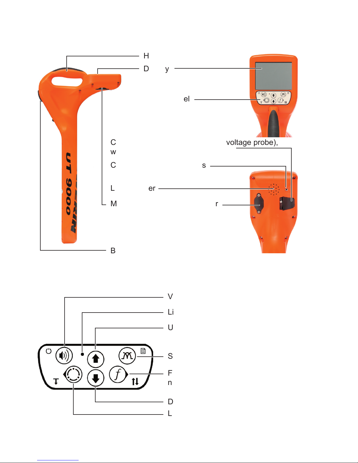
UT 9000 R receiver
Handle
Display
Control panel
Connection for accessories (step-voltage probe),
with cover
Connection for headphones
Battery compartment
Fig. 1: UT 9000 R receiver
Volume, ON/OFF, measuring mode
Light sensor
Frequency, direction recognition,
next, select
Location type, depth, back
Fig. 2: UT 9000 R receiver control panel (functions of the keys)
Loudspeaker
Mini USB connector, with cover
Up, gain up
Signal behaviour, menu
Down, gain down
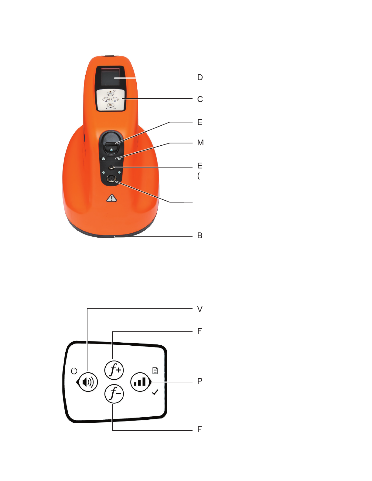
UT 9012 TX generator
Display
Control panel
Eye ring for carrying strap
Mini USB connector, with cover
External power supply connector
(vehicle cable)
Battery compartment
Fig. 3: UT 9012 TX generator
Volume, ON/OFF, back
Frequency up
Fig. 4: Generator control panel (functions of the keys)
Power level, menu, next, select
Frequency down
Connection for accessories
(set of cables, cable clamp)

Information about this document
The warnings and notes in the document mean the following:
A
WARNING!
Risk of personal injury. Can result in serious injury or
death.
A
CAUTION!
Risk of personal injury. Can result in injury or a risk to
health.
NOTICE!
Risk of damage to property.
Note:
Tips and important information.
Enumerated lists (numbers, letters) are used for:
● Instructions that must be followed in a specic sequence
Bullet lists (bullet points, dashes) are used for:
● Lists
● Instructions comprising only one action

I
Contents Page
1 Introduction .............................................................................1
1.1 Warranty ....................................................................................1
1.2 Purpose ..................................................................................... 2
1.3 Intended use .............................................................................3
1.4 General safety information ........................................................3
2 UT 9000 R receiver ..................................................................4
2.1 General .....................................................................................4
2.2 Location methods, location types and signal behaviour ............5
2.3 Control panel ............................................................................. 7
2.4 Display ......................................................................................9
2.5 Conguringthedevice(menu) ................................................13
2.5.1 Frequencies menu item ........................................................14
2.5.2 Settings menu item ..............................................................14
2.5.2.1 Language ..........................................................................15
2.5.2.2 Units .................................................................................. 15
2.5.2.3 Backlight............................................................................15
2.5.2.4 Shutdown Timer ................................................................15
2.5.2.5 Communications ...............................................................16
2.5.3 Options menu item ............................................................... 17
2.5.3.1 Audio Mode ....................................................................... 17
2.5.3.2 Audio Style ........................................................................ 18
2.5.3.3 Gain...................................................................................18
2.5.3.4 Autodepth .......................................................................... 18
2.5.3.5 Offset Depth ...................................................................... 18
2.5.4 System Info menu item ........................................................19
2.5.5 Ambient Noise menu item .................................................... 19
2.5.6 TX Control menu item ..........................................................19
2.6 Power supply ........................................................................... 20
3 UT 9005 TX / UT 9012 TX generator ..................................... 22
3.1 General ...................................................................................22
3.2 Operating modes ..................................................................... 22
3.3 Control panel ........................................................................... 23
3.4 Display ....................................................................................24
3.5 Conguringthedevice(menu) ................................................27
3.5.1 Frequencies menu item ........................................................28
3.5.2 Settings menu item ..............................................................28
3.5.2.1 Backlight............................................................................28

II
Contents Page
3.5.2.2 Output ...............................................................................28
3.5.2.3 Meter ................................................................................. 30
3.5.2.4 Communications ...............................................................30
3.5.3 Options menu item ............................................................... 31
3.5.3.1 Language ..........................................................................31
3.5.3.2 Defaults ............................................................................. 32
3.5.3.3 Step-voltage probe ............................................................33
3.5.4 System info menu item .........................................................33
3.6 Power supply ........................................................................... 34
3.6.1 Changing the batteries ......................................................... 35
3.6.2 Lithium-ion rechargeable battery ..........................................36
3.6.2.1 Safety information regarding the lithium-ion rechargeable
battery ...............................................................................36
3.6.2.2 Storage of the rechargeable battery..................................36
3.6.2.3 Charging the battery..........................................................37
4 Using the UT 9000 system .................................................... 39
4.1 Device pairing .........................................................................39
4.1.1 Pairing the generator and the receiver ................................. 39
4.1.2 Disconnecting the generator and the receiver .....................40
4.2 Frequency selection ................................................................40
4.2.1 Enabling a frequency ...........................................................42
4.2.2 Selecting the frequencies ..................................................... 42
4.3 Gain control on the receiver ....................................................43
4.4 Depth measurement ................................................................ 44
4.4.1 Determining the depth automatically .................................... 44
4.4.2 Determining the depth manually ..........................................45
4.4.3 Determining the offset depth ................................................45
4.5 UT 9000 software ....................................................................47
5 Active location: lines ............................................................49
5.1 Determining the ambient noise ...............................................49
5.2 Energising a line ...................................................................... 51
5.2.1 Galvanic energising ..............................................................51
5.2.1.1 Parallel connection ............................................................52
5.2.1.2 Points to note when changing the set of cables ................54
5.2.2 Inductive energising .............................................................55
5.2.2.1 Energising with a cable clamp...........................................55
5.3 Locating a line .........................................................................56
5.4 Direction recognition ...............................................................58

III
Contents Page
5.5 High Power .............................................................................. 60
6 Active location: sondes ........................................................ 62
7 Passive location ....................................................................65
8 Troubleshooting ....................................................................68
8.1 Sources of error when locating ...............................................68
8.2 Problems with the receiver ...................................................... 69
8.3 Problems with the generator ...................................................69
9 Appendix ................................................................................ 71
9.1 Technical data .........................................................................71
9.1.1 UT 9000 R receiver ..............................................................71
9.1.2 UT 9005 TX / UT 9012 TX generator ...................................72
9.2 Pre-set frequencies (factory settings) .....................................74
9.2.1 UT 9000 R receiver ..............................................................74
9.2.2 UT 9005 TX / UT 9012 TX generator ...................................75
9.3 Accessories and consumables ................................................ 76
9.4 EC Declaration of Conformity .................................................. 76
9.5 Advice on disposal ..................................................................77
10 Index ....................................................................................... 78

1
1 Introduction
1 Introduction
1.1 Warranty
The following instructions must be complied with in order for any
warranty to be applicable regarding functionality and safe operation of this equipment. The product must only be operated by
qualiedspecialisttechnicians.
●
Read these operating instructions prior to operating the product.
● Use the product only as intended.
● Repairs and maintenance must only be carried out by special-
ist technicians or other suitably trained personnel. Only spare
parts approved by Hermann Sewerin GmbH may be used
when performing repairs.
● Use only suitable battery types.
● Changesormodicationstothisproductmayonlybecarried
out with the approval of Hermann Sewerin GmbH.
●
Use only Hermann Sewerin GmbH accessories for the product.
Hermann Sewerin GmbH shall not be liable for damages resulting
from the non-observance of this information. The warranty conditions of the General Terms and Conditions ("AGB") of Hermann
Sewerin GmbH are not affected by this information.
In addition to the warnings and other information in these Operating Instructions, always observe the generally applicable safety
and accident prevention regulations.
The manufacturer reserves the right to make technical changes.

2
1 Introduction
1.2 Purpose
UT 9000 is an electronic location system for detecting electri-
cally conductive lines laid in the ground. The system comprises the UT 9000 R receiver and a generator (UT 9012 TX or
UT 9005 TX). Data is sent between the receiver and the generator via bidirectional radio.
The UT 9000 can be used for:
● Locating and tracking lines
Lines refers here to both power and signal cables as well as
supply lines, for example.
● Determining the depth of a line
Location can be carried out passively or actively. For active lo-
cation,therequiredelectromagneticeldisgeneratedbymeans
of a generator. Passive location makes use of existing electro-
magneticelds.
As with other systems, it is always advisable to check the plausibility of the result of the UT 9000 location process.
Note:
In these operating instructions, we describe the UT 9000 system
working in conjunction with a UT 9012 TX generator. The descriptions are also valid for the UT 9005 TX generator, however
it offers fewer functions.
All descriptions refer to the system as delivered (factory settings).
The manufacturer reserves the right to make changes.

3
1 Introduction
1.3 Intended use
UT 9000 is intended for professional industrial and commercial
use. The appropriate specialist knowledge is required to operate
the device.
Note:
If necessary, learn more about pipe location theory before commencing practical work with the UT 9000.
Thesystemmustonlybeusedfortheapplicationsspeciedin
Section 1.2.
1.4 General safety information
● Contact the local utility companies to establish the route of un-
derground cables and lines before commencing location work.
●
Before starting work, check that the equipment is in good working order. Never use damaged or faulty equipment.
● Never use the equipment in the vicinity of explosive areas.
●
Always adequately secure the setup locations of the equipment to prevent injury to persons and damage to vehicles.
● Always observe the applicable safety regulations when work-
ing on electrical installations (e.g. power cables).
● Do not drop the devices.
●
Never place the devices in places where they are at risk of
falling.
● Ensure that no dirt or moisture can get into the connections
on the devices.
● Always observe the permitted operating and storage temper-
atures.
● Do not immerse the devices in liquids.

4
2 UT 9000 R receiver
2 UT 9000 R receiver
2.1 General
The UT 9000 R receiver receives the signals from electromag-
neticelds.Thesignalsarerelayed:
● audibly via a loudspeaker or headphones
● visually on the display
Theeldstrengthisdisplayedingraphicalandnumericalformon
the display. The directional arrow and other graphical elements
help guide you towards the location object.
Youwill ndanoverview withthe namesofthe receiverparts
inside the front cover (Fig. 1).
The selected volume of the loudspeaker or headphones does
not affect the sensitivity of the device, i.e. loud signals are not
necessarily strong signals.
The UT 9000 R receiver can be used for both active and passive
location. Semi-automatic gain control can be used to simplify
active location.
The lower part of the receiver contains multiple antennas. The
selected signal behaviour determines exactly how they combine
within the device.
5
2 UT 9000 R receiver
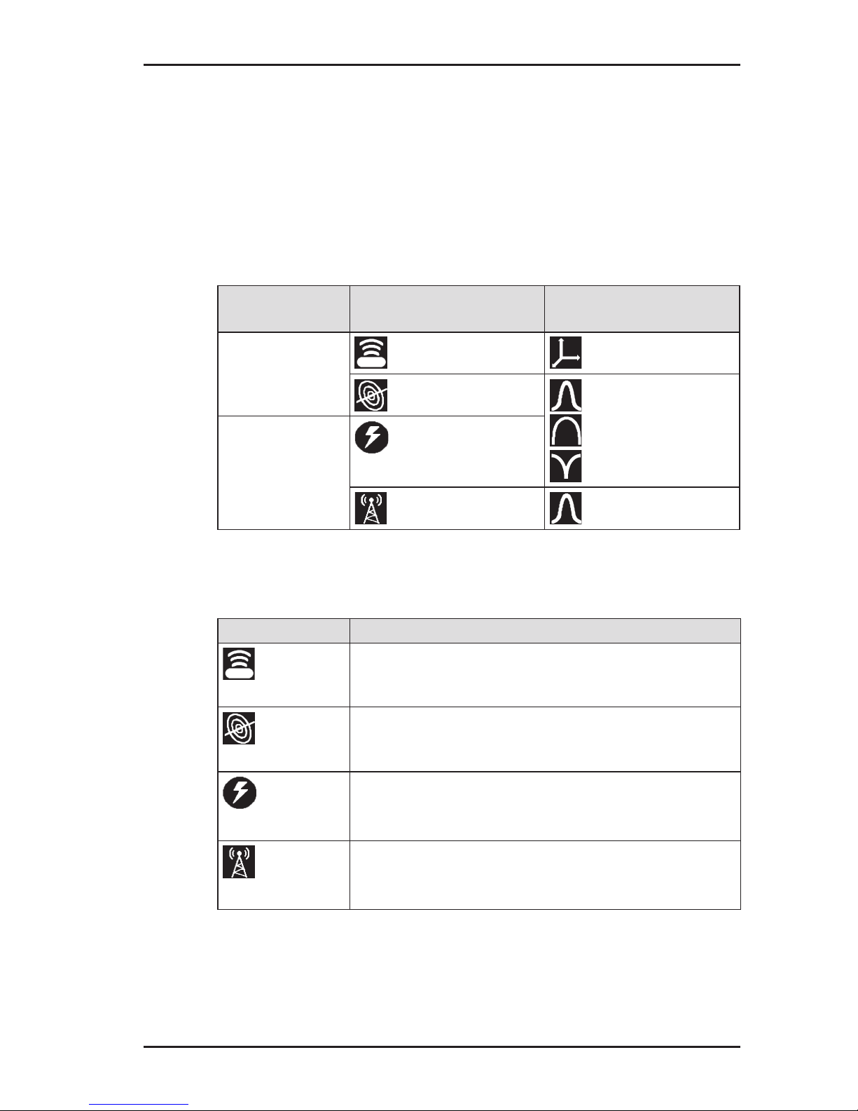
2.2 Location methods, location types and signal behaviour
Active and passive location with the UT 9000 are referred to location methods.
Two different location types are available for each of the location
methods. Different signal behaviours can be selected depending
on the location type. The location types and signal behaviour are
shown using symbols.
Location
mode
Location type Signal behaviour
active
location
sonde coordinates
line maximum narrow
maximum wide
minimum
passive
location
current
radio maximum narrow
Location types
Location type Suitable location objects
Sonde
● non-metal pipes carrying a sonde
Line
● lines being energised by a generator
(see section 3.2 on page 22)
Current
● current-carrying cables
– available frequencies: 50 Hz, 100 Hz,
150 Hz or 60 Hz, 120 Hz, 180 Hz
Radio
● metallic lines
– available frequency: radio, i.e. frequency
range 11.6 – 31.4 kHz (VLF range)
6
2 UT 9000 R receiver
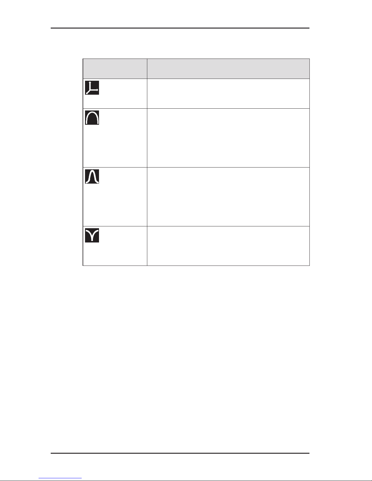
Signal behaviour
Signal
behaviour
Description
Coordinates
● for precise location of a sonde
● fordeterminingwherebre-opticcables
end
Maximum wide
● to determine the location of a line using
the maximum method
● in comparison to maximum narrow sig-
nal behaviour:
– wider range
– lower accuracy
Maximum
narrow
● to determine the location of a line using
the maximum method
● in comparison to maximum wide signal
behaviour:
– lower range
– greater accuracy
Minimum
● to determine the location of a line using
the minimum method (zero signal)
● signicantdistinctsignalcurveoverthe
line

7
2 UT 9000 R receiver
2.3 Control panel
The control panel consists of six keys (Fig. 2 inside front cover).
Some keys have more than one function.
Key Function Action
Volume
● to increase the
volume or turn the
sound off
● presskeybriey
several times
ON/OFF
● to switch the de-
vice on
● press the key
● to switch the de-
vice off
● hold down the key
Measuring
mode
● to close the menu
and return directly
to the measuring
mode
● press the key
Location
type
● to select the loca-
tion type
● press the key
Depth
● in the case of
determining the
depth manually: to
enable the depth
measurement
● press the key until
an acoustic signal
sounds
Back
● in a menu: to re-
turn to the next
level up
● press the key
briey
Up
● in a menu: to se-
lect or to move up
● press the key
Gain up ● to increase the
gain
● press the key
(semi-automatic
gain control adjustment)
● press the key re-
peatedly (manual
gain control adjustment)
8
2 UT 9000 R receiver
Key Function Action
Down
● in a menu: to se-
lect or to move
down
● press the key
Gain down ● to reduce the gain ● press the key
(semi-automatic
gain control adjustment)
● press the key re-
peatedly (manual
gain control adjustment)
Signal
behaviour
● to select the sig-
nal behaviour
● press the key
briey
Menu
● to open a menu ● hold down the key
Frequency
● to select a fre-
quency
● presskeybriey
several times
Direction
recognition
● to enable direction
recognition
● press the key until
an acoustic signal
sounds
Next
● in a menu: to go
to the next level
down
● press the key
Select ● to select a setting
(enable/disable)
● press the key
9
2 UT 9000 R receiver
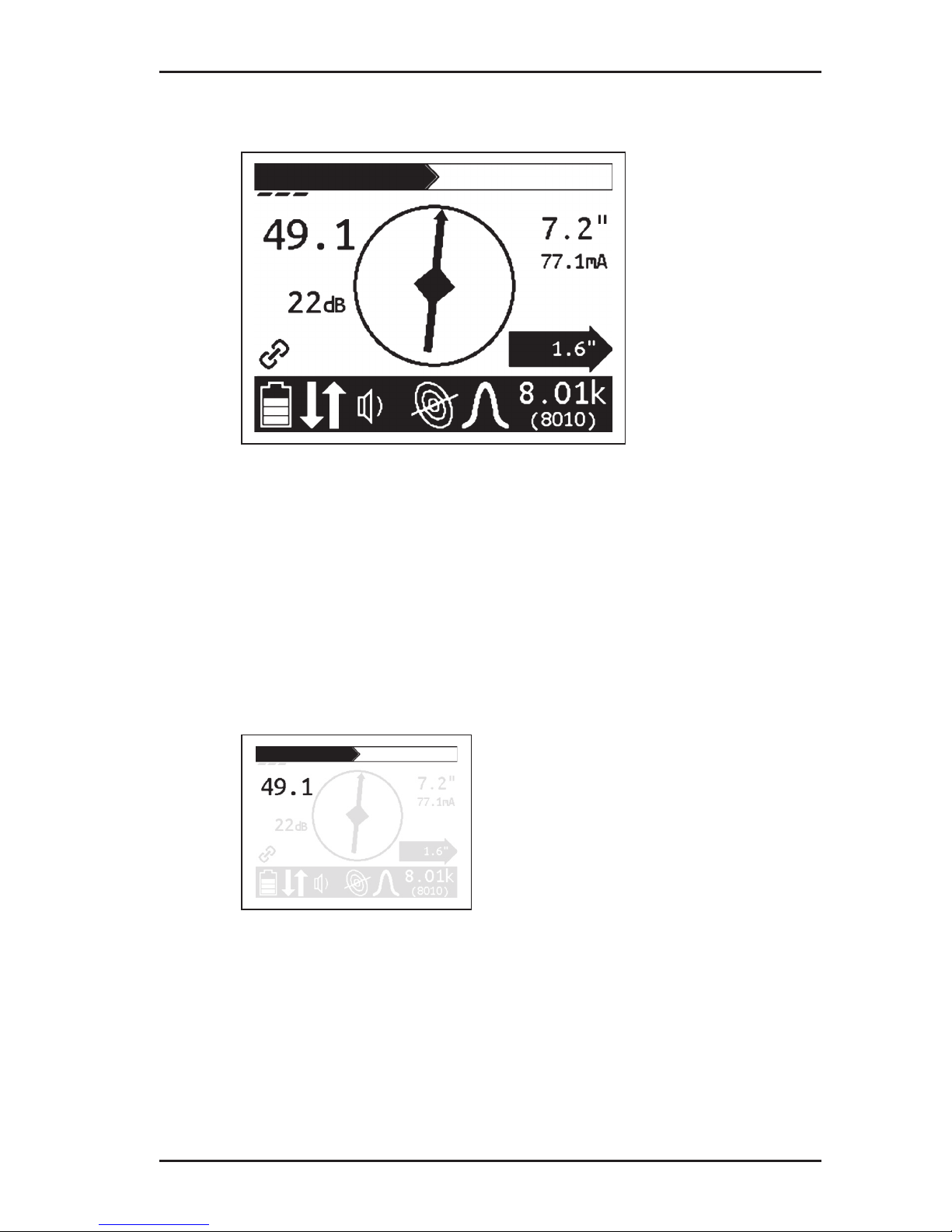
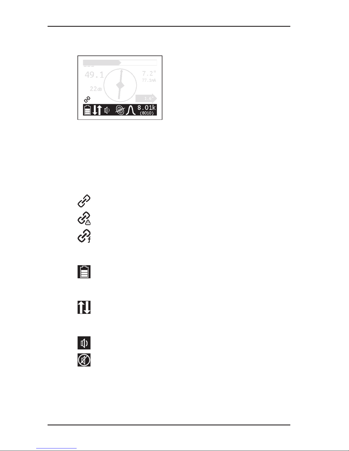
2.4 Display
Fig. 5: UT 9000 R receiver display (overview)
Theupperareadisplaystheeldstrengthandgainingraphical
form. The lower area consists of a tool bar which displays the
current settings and conditions using symbols.
The central area is used to help guide you towards the location
object with the help of graphical elements. The current measurement values are displayed on the right and left-hand sides.
Field strength
Fig. 6: Receiverdisplay–eldstrengthdisplay
Theeldstrengthisdisplayed:
● numerically
in the example (Fig. 6): 49.1
● graphically
thelargerthebar,thegreatertheeldstrength.
10
2 UT 9000 R receiver
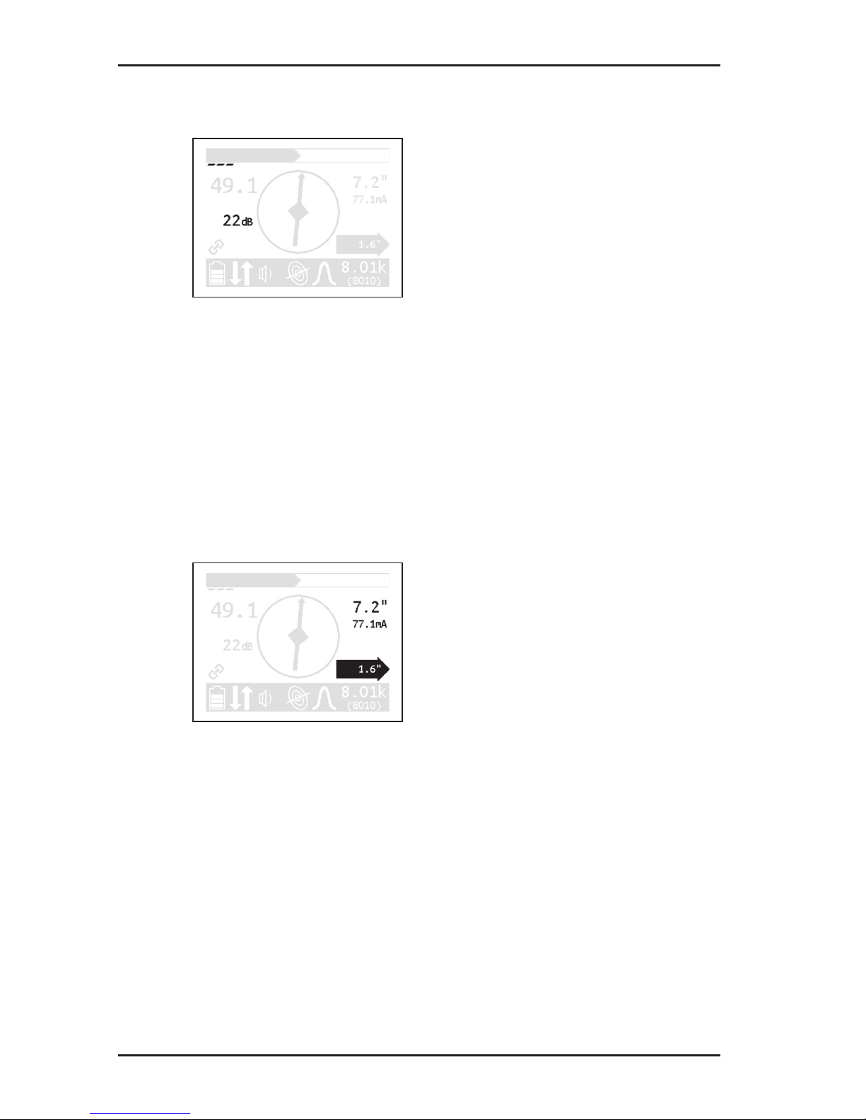
Gain
Fig. 7: Receiver display – gain display
Theeldstrengthisdisplayed:
● numerically
in the example (Fig. 7): 22 dB
● graphically
The more segments that are visible, the higher the gain.
Depth
Fig. 8: Receiver display – depth and distance display
The depth is displayed numerically. The unit of measurement
can be set.
in the example (Fig. 8): 7.2"
If offset depth determination is enabled, the distance to the location object is also displayed inside a black arrow.
in the example (Fig. 8): 1.6"
In addition, the current is also shown on the display. This helps for
example in identifying the energised line in case of parallel lines.
in the example (Fig. 8): 77.1 mA
11
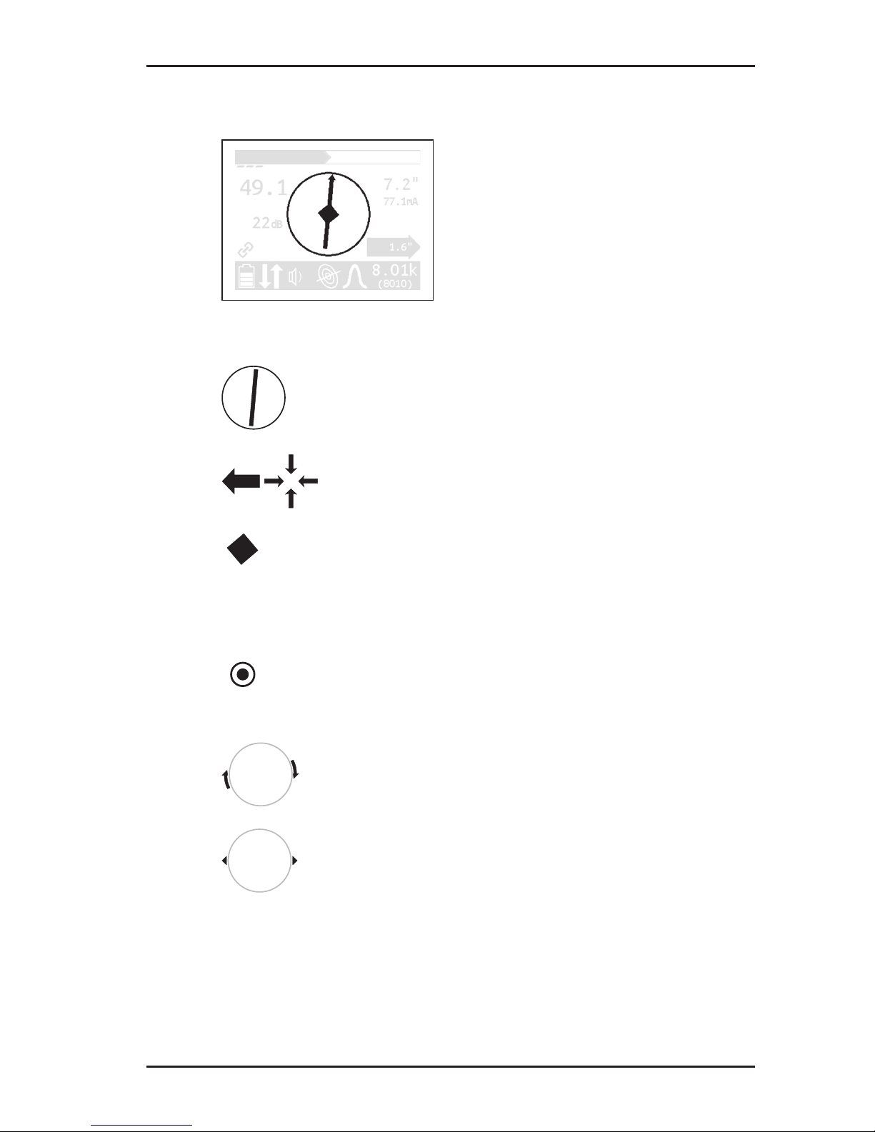
2 UT 9000 R receiver
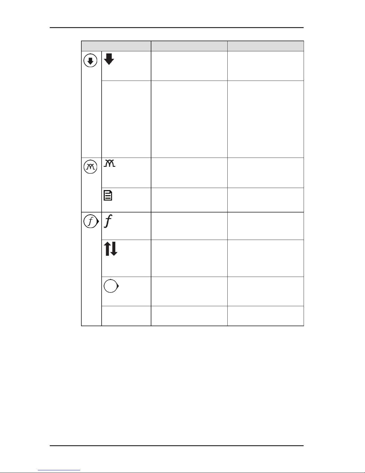
Graphical elements
Fig. 9: Receiver display – graphical elements
Compass with needle
● the compass needles show the position of the
line.
Directional arrows
● the receiver needs to be moved in the direction
of the arrow shown.
Diamond
● the receiver is located directly above the loca-
tion object.
When locating sondes:
Point
● the receiver is located above a minimum in the
signal curve.
Turn arrows
● the receiver needs to be turned in the direction
of the arrow shown.
Tips
● the tips show the position of the sonde.
12
2 UT 9000 R receiver
Symbols
Fig. 10: Receiver display – symbols
The selected frequency is displayed twice on the right-hand side
of the tool bar. For frequencies over 1,000 Hz, the top value is
displayed in kHz and underneath in Hz.
Information about the generator
receiver and generator paired
generator beyond radio range
selected frequency not enabled in generator
Battery status
remaining battery capacity
Miscellaneous
direction recognition enabled
Volume
tone switched on
tone switched off
13
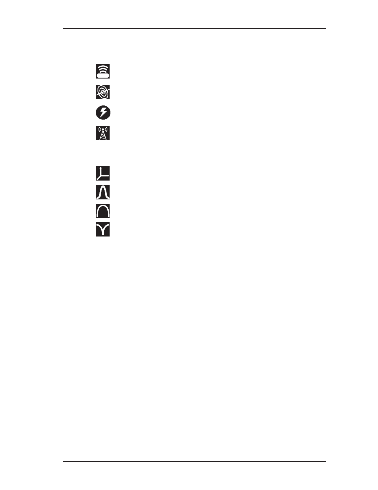
2 UT 9000 R receiver
Location type
sonde
line
current
radio
Signal behaviour
coordinates
maximum narrow
maximum wide
minimum
2.5 Conguring the device (menu)
The menu can be used for making settings and for retrieving information about the device. The following menu items are available:
● Frequencies
● Settings
● Options
● System Info
● Ambient noise
● TX Control
Opening the menu
With the device switched on:
● Hold down the menu key. The menu appears.

14
2 UT 9000 R receiver
Opening a menu item
With the menu open:
1. Press the up or down key. The selected menu item will be
highlighted.
2. Press the next key. The selected menu item is opened.
Changing the settings
With the menu item for which you wish to change the settings:
1.
Press the up or down key. The selected setting is highlighted.
2. Press the next key. The setting will be enabled/disabled.
3. Press the back key. The setting will be accepted. The device
will be returned to the next level up.
Exiting the menu or a menu item
With the menu or a menu item open:
●
Press the back key. The device will be returned to the next
level up.
Returning directly to the measuring mode
With the menu or a menu item open:
●
Press the volume key. The device will return directly to the
measuring mode.
2.5.1 Frequencies menu item
The Frequencies menu item is used to enable or disable the
pre-set frequencies. Symbols indicate which individual frequencies are suitable for the different location types.An explanation
of these symbols can be found in section 9.2.1 on page 74.
For more detailed information on which frequencies to select,
please refer to section 4.2 on page 41.

15
2 UT 9000 R receiver
2.5.2 Settings menu item
The Settings menu item can be used to modify the following
settings:
● Language
● Units
● Backlight
● Shutdown Timer (shutdown time)
● Communications
2.5.2.1 Language
The Language menu item is used to change the language used
on the display.
2.5.2.2 Units
The Units menu item is used to modify the units of measurement
for the distance (depth) and offset depth.
2.5.2.3 Backlight
The Backlight menu item is used to switch the display backlight
on and off.
If the backlight is enabled (Autom./automatic), the display is lit
up in the case of low levels of light. The sensor for this automatic
control can be found on the control panel.
2.5.2.4 Shutdown Timer
The Shutdown Timer menu item is used to set the time after
which the device should be shut down if not in use.
If Always On is selected, the device never shuts down auto
-
matically.

16
2 UT 9000 R receiver
2.5.2.5 Communications
The following options are available in the Communications
menu item:
● Radio On/Off
● Bluetooth
● Link Info (linking information)
● Link TX
● Unlink TX
Radio On/Off
The Radio On/Off menu item can be used to disconnect or re-
establish the radio connection between the generator and the
receiver.
An example of when it may be necessary to disconnect the radio
connection is when attempting to make a secure connection to a
Bluetooth device (e.g. GPS mouse).
Note:
Disconnecting the radio connection does not cut an existing pairing of generator and receiver.
Bluetooth
The Bluetooth menu item is used for saving location results on
an external Bluetooth device (e.g. GPS mouse), making it possible to document location results.
The receiver needs to be connected to the Bluetooth device in
order for data transmission to be possible. Once the data has
been transmitted, the devices are disconnected again.

17
2 UT 9000 R receiver
Pairing information
The Link Info menu item is used to display information on pairing
with a generator.
If a receiver is paired with a generator, the device number of the
generator is displayed in Linked To.
Link TX
The menu item Link TX is used to pair a receiver with a generator.
For more detailed information on pairing, please refer to section 4.1.1 on page 39.
Unlink TX
The menu item Unlink TX is used to unpair an existing link between a receiver and a generator.
For more detailed information on unpairing, please refer to section 4.1.1 on page 39.
2.5.3 Options menu item
The Options menu item can be used to modify the following:
● Audio Mode
● Audio Style
● Gain
● Autodepth
● Offset Depth
2.5.3.1 Audio Mode
The Audio Mode menu item can be used to set the acoustic
signal type.
● Pitch
The pitch of the signal changes (up/down).
● Volume
The volume of the signal changes (loud/quiet).

18
2 UT 9000 R receiver
2.5.3.2 Audio Style
The Audio Style menu item is used for setting which kind of
sound reproduction is used.
● Classic
● Smooth
2.5.3.3 Gain
The Gain menu item is used to set how the gain on the received
signals is readjusted. The gain control must always be readjusted
by the user.
● Manual
Incremental gain control adjustment up to desired gain.
● Semi-auto (semi-automatic)
Gain control adjustment is carried out within the optional gain
range.
More information about adjusting the gain can be found in section 4.3 on page 43.
2.5.3.4 Autodepth
The Autodepth menu item is used to set how the depth of the
location object should be determined.
● Autodepth (automatically)
The depth is displayed automatically as soon as the device is
located directly above the location object.
● Manual
The user need to press the depth key for the depth to be determined.
2.5.3.5 Offset Depth
The Offset Depth menu item can be used to enable or disable
the determination of the offset depth.
For more detailed information on the offset depth, please refer to
section 4.4.3 on page 45.

19
2 UT 9000 R receiver
2.5.4 System Info menu item
The System Info menu item displays information about the device. This information may be spread across several pages.
● Press the down key to display all the information.
2.5.5 Ambient Noise menu item
The Ambient Noise menu item can be used to determine which
of the enabled frequencies are present and at what strength in
the surrounding areas for each location type.
For more detailed information on ambient noise, please refer to
section 5.1 on page 49.
2.5.6 TX Control menu item
Note:
The TX Control menu item is only available when the receiver
is paired with a generator.
With the help of the TX Control menu item, the receiver is able
to control the generator in measuring mode. The generator must
be switched on.
Thefollowing settingscanbe modiedfor thecurrent location
situation:
● Power level
● Dual Output, as long as a Y-cable (double set of cables) is
attached to the generator.
Thischangestheassignation oftheowof currentbetween
the red and white cables. The cable not in use is shown as
crossed out.
Information on dual output can be found in section 3.5.2.2 on
page 28.

20
2 UT 9000 R receiver
Controlling the generator via the receiver
On the receiver:
1. In the menu, select: Settings > TX Control.
The operating mode display appears. The symbol of the func-
tionwhichcanbemodiedashes.
− Press the down or up key to change between power level
and dual output.
−
Click on the next key to change the corresponding settings.
2. Click on the back key to accept the changes.
2.6 Power supply
The device can be operated with either disposable or regular
rechargeable batteries.
NOTICE! Risk of damage due to leaking batteries
● Never mix power sources of different types (disposable or re-
chargeable), capacity, condition (new or used) or manufacturer.
 Loading...